Tabla de contenido
Publicidad
Idiomas disponibles
Idiomas disponibles
Enlaces rápidos
Einbauanleitung für Fettabscheideranlagen System
DE
KLsepa.pop
>> Seite 1-16
EN
Assembly and Installation Instructions Grease Separator
KLsepa.pop
>> Page 17-32
Notice d'installation des Séparateurs de graisses GRAF
FR
>> Page 33-47
Instrucciones de montaje Separador de grasa GRAF
ES
>> Página 48-63
KLsepa.pop
Publicidad
Tabla de contenido

Manuales relacionados para Graf KLsepa.pop NS 1 SAPHIR


Resumen de contenidos para Graf KLsepa.pop NS 1 SAPHIR
- Página 1 KLsepa.pop Einbauanleitung für Fettabscheideranlagen System KLsepa.pop >> Seite 1-16 Assembly and Installation Instructions Grease Separator KLsepa.pop >> Page 17-32 Notice d’installation des Séparateurs de graisses GRAF >> Page 33-47 Instrucciones de montaje Separador de grasa GRAF >> Página 48-63...
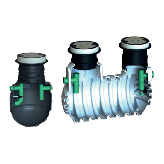
- Página 2 Einbauanleitung für Fettabscheideranlagen System KLsepa.pop Fettabscheider SAPHIR (ohne Verlängerung und Abdeckung) Art.-Nr. 108000 NS 1 Art.-Nr. 108001-108004 NS 2 Art.-Nr. 108005 NS 4 Fettabscheider DIAMANT (ohne Verlängerung und Abdeckung) Art.-Nr. 108006 NS 4 Art.-Nr. 108007 NS 7 Art.-Nr. 108008 NS 10 Art.-Nr.
- Página 3 Anlieferung gegen eine geeignete Abdeckung ausgetauscht werden (Teleskop-Domschacht mit entsprechender Abdeckung). Es sind nur original GRAF – Abdeckungen oder von Fa. GRAF schriftlich freigegebene Abdeckungen zu verwenden. Die Firma GRAF bietet ein umfangreiches Sortiment an Zubehörteilen, die alle aufeinander abgestimmt sind und zu kompletten Systemen ausgebaut werden können.
- Página 4 2. Einbaubedingungen 2. Einbaubedingungen 2.1. Einbaugrundsätze Vorhandene Entwässerungsleitungen sind auf passende Anschlusshöhen zu prüfen. Die Werkstoffe der Zu- und Ablaufleitungen müssen gegen das fetthaltige Abwasser beständig sein. Der erforderliche Leitungsquerschnitt, in Abhängigkeit von der Nenngröße des Abscheiders und das erforderliche Leitungsgefälle nach den entsprechenden Normen (EN 752-4, EN 12056-2, EN 1825-1) ist zu beachten.
- Página 5 2. Einbaubedingungen 2.3. Entlüftung Zu- und Ablaufleitungen an Abscheideranlagen für Fette sind ausreichend zu belüften. Die Zulaufleitung ist als Lüftungsleitung bis über Dach zu führen. Alle Anschlussleitungen über 5 m sind gesondert zu entlüften. Hat die Zulaufleitung auf einer Länge von zehn Metern keine gesonderte Lüftung, muss zusätzlich möglichst nah am Abscheider eine weitere Lüftungsleitung angeschlossen werden.
- Página 6 2. Einbaubedingungen 2.4.2. Hanglage, Böschung etc. Beim Einbau des Behälters in unmittelbarer Nähe (< 5 m) eines Hanges, Erdhügels oder einer Böschung (größer 5°) muss eine statisch berechnete Stützmauer zur Aufnahme des Erddrucks errichtet werden. Die Mauer muss die Behältermaße um mind. 500 mm in alle Richtungen überragen und einen Mindestabstand von 1000 mm zum Behälter haben.
- Página 7 2. Einbaubedingungen 2.4.4. Begehbare Abdeckung (A15 nach EN124) Wird der Behälter nicht befahren und es wird keine Lastverteilerplatte eingebaut, muss der Abstand zu befahrbaren Flächen der Baugrubentiefe entsprechen. Tankserie Saphir Tankserie Diamant > H > H 2.4.5. Befahrbare Abdeckung PKW (B125 nach EN124) Bei PKW-Befahrbarkeit ist eine entsprechende Abdeckung nach EN 124 der Klasse B zu verwenden.
- Página 8 2.4.6. Befahrbare Abdeckung LKW/SLW40 (D400 nach EN124) Bei Befahrbarkeit mit Schwerlastverkehr ist eine entsprechende Abdeckung nach EN 124 der Klasse D zu verwenden. Zusätzlich ist eine Lastverteilungsplatte bauseits zu stellen (Bewährungspläne bei der GRAF erhältlich). Tankserie Saphir Tankserie Diamant 3. Einbau und Montage 3.1.
- Página 9 3. Einbau und Montage 3.2. Endmontage 3.2.1. Ausrichten des Behälters Der Behälter ist stoß frei und mit geeignetem Gerät in die vorbereitete Baugrube einzubringen. Nach dem Setzen des Behälters ist dieser in der Grube so auszurichten, dass der Zulauf in der Achse der Zulaufleitung liegt. Der Behälter muss senkrecht stehen.
- Página 10 3. Einbau und Montage 3.2.3. Anschluss von Zu- und Ablauf Die Zu- und Ablaufleitung sind anzuschließen, wenn die Grubenverfüllung die Anschlüsse erreicht hat. 3.2.4. Ausrichten der Einbauteile Nach dem Anschließen von Zu- und Ablauf ist zu kontrollieren, ob die Einbauteile senkrecht stehen.
- Página 11 3. Einbau und Montage Die Verbindungsstrecke zwischen Abscheider und Steuereinheit ist möglichst kurz zu halten. Unnötige Richtungsänderungen, insbesondere solche mit Abwinkelungen über 45° sind zu vermeiden. Das Kabelleerrohr sollte ein stetiges Gefalle zum Abscheider aufweisen. Kondenswasserbildung innerhalb des Kabellehrrohres kann durch einen luftdichten Abschluss des Leerrohres auf der Seite der Steuereinheit, minimiert werden.
- Página 12 3. Einbau und Montage 3.2.7. Montage von Zwischenstück und Teleskop-Domschacht Profildichtung wird ⑥ Tanköffnung montiert Zwischenstück ⑤ bis zum Anschlag eingeschoben. Vor dem Einschieben des Zwischenstückes ist die Dichtung mit Schmierseife einzuschmieren. In das Zwischenstück wird die Dichtung ④ montiert und der Teleskopdomschacht ③...
- Página 13 3. Einbau und Montage 3.3.2. PKW-Befahrbarkeit (Abdeckung B125) Wird der Behälter unter PKW befahrenen Flächen installiert, muss Teleskopdomschacht im Kragenbereich mit Beton (Festigkeitsklasse C25/30) unterbaut werden. Die anzufüllende Betonschicht muss umlaufend mind. 300 mm breit und ca. 200 mm hoch sein. Anschließend wird in die Nut des Teleskop-Domschacht ③...
- Página 14 3. Einbau und Montage 3.4. Warnanlage Abstand Fettspeicher (80%) Überstau [mm] [mm] NS1-200, NS2-200-2 1000 NS2-200-3 1200 NS2-400 1200 NS2-500, NS4-500 1000 1500 NS4-700. NS7-700 1250 NS10-1500, NS15-1500 1000 1450 Die Montage und Wartung der Warnanlage entnehmen Sie bitte der Original- Bedienungsanleitung der Warnanlage.
- Página 15 4. Technische Daten 4. Technische Daten 4.1. Tankserie Saphir KLsepa.pop NS 1-200 NS 1-200-3, NS 2-200-3 NS 2-500 NS 2-200-2 NS 2-400 NS 4-500 Durchmesser d [mm] 1125 1155 1155 Höhen [mm] 1050 1375 [mm] 655 – 855 740 - 940 740 - 940 [mm] 1500 - 1700...
- Página 16 4. Technische Daten 4.2. Tankserie Diamant KLsepa.pop NS 4-700 NS 10-1500 NS 2-700 NS 15-1500 Höhen [mm] 1085 1280 [mm] 680 – 970 740 – 1030 [mm] 1765 – 2055 2020 – 2310 h [mm] 1150 1400 [mm] 1655 1910 Anschlüsse Gewicht [kg]...
- Página 17 4. Technische Daten 4.3. Probeentnahmeschacht DN 600 Probeentnahmeschacht DN 160 DN 200 Zulauf Höhen [mm] [mm] 860 - 1060 880 - 1080 [mm] 1140 - 1340 1140 - 1340 [mm] 1000 1000 Gewicht [kg] www.graf.info KLsepa.pop 2019-10...
- Página 18 In case of non- Safety notices compliance, all warranty claims 19 Installation conditions shall lapse. For all add-on items 23 from GRAF, you shall receive Assembly and Installation separate installation instructions 30 Technical data included with the transport packaging.
- Página 19 (telescopic dome shaft with respective cover). Only original GRAF covers or covers approved in writing by GRAF must be used. GRAF offers a wide range of accessory parts which are precisely coordinated and can be used to complete systems. The use of accessories that have not been approved by GRAF results in the exclusion of the warranty/guarantee.
- Página 20 2. Installation conditions 2. Installation conditions 2.1. Installation basics Existing drainpipes should be checked for matching connection heights. The materials of the inlet and outlet pipes must be resistant to wastewater containing grease. The required pipe diameter, depending on the nominal size of the separator and the required slope of the line according to the corresponding standards (EN 752-4, EN 12056-2, EN 1825-1), must be adhered to.
- Página 21 2. Installation conditions 2.3. Venting Inlet and outlet lines on grease separators must be adequately vented. The inlet line must be run as a ventilation duct up to the top of the roof. All connecting lines longer than 5m must be vented separately. ...
- Página 22 2. Installation conditions 2.4.2. Slope, embankment, etc. During the installation of the tank in close proximity (<5 m) to a slope, mound or embankment (greater than 5°), a statically calculated retaining wall must be built to absorb the active earth pressure. The wall must exceed the tank dimensions by at least 500 mm and must have a minimum clearance of 1000 mm to the tank.
- Página 23 2. Installation conditions 2.4.4. Accessible cover (A15 in accordance with EN124) If there is no car traffic over the tank area and no load distribution plate is installed, the clearance to the passable areas must correspond with the building pit depth. Saphir tank series Diamant tank series >...
- Página 24 In case of heavy truck traffic, an appropriate cover according to EN 124 class D must be used. In addition a load distribution plate must be provided on site (structural drawing available at GRAF GmbH). Saphir tank series Diamant tank series 3.
- Página 25 3. Assembly and Installation 3.2. Final installation 3.2.1. Positioning of the tank The tank must be placed shock-proof and with adequate equipment into the prepared building pit. After placing the tank, it must be positioned in the pit in such a way that the inlet is aligned along the axis of the inlet line.
- Página 26 3. Assembly and Installation 3.2.3. Connection of inlet and outlet Connect the inlet and outlet lines once the pit has been filled as far as the connections. 3.2.4. Positioning of the assembly components After connecting the inlet and outlet lines, check whether the assembly components are in a vertical position.
-
Página 27: Tank Installation
3. Assembly and Installation 3.2.5. Tank installation Saphir tank series Diamant tank series Up to two adaptors with respective seals can be installed. ① Concrete cover ⑤ Adapter* ② Tubular seal ⑥ Profile gasket ③ Telescope ⑦ Separator tank ④ Gasket for adaptor KLsepa.pop... - Página 28 3. Assembly and Installation 3.2.6. Installation of adaptors and the telescopic dome shaft The profile gasket ⑥ must be mounted onto the tank opening and the adaptor ⑤ inserted as far as the stop. Before inserting the adaptor, the seal must be lubricated with soft soap.
- Página 29 3. Assembly and Installation 3.3.2. Suitable car traffic (cover B125) If the tank is installed underneath an area with car traffic, concrete underlay (property class C25/30) must be placed in the collar area under the telescopic dome shaft for trucks. The circumference of the concrete layer to be filled in must be at least 300 mm wide approx.
- Página 30 3. Assembly and Installation 3.4. Commissioning If there is not already one in place, the nameplate delivered with every separator must be attached via a chain to the underside of the telescopic dome shaft cover. To commission the separator, fill it with grease-free and oil-free water until the water begins to flow out of the discharge pipe.
- Página 31 4. Technical data 4. Technical data 4.1. Saphir tank series KLsepa.pop NS 1-200 NS 1-200-3, NS 2-200-3 NS 2-500 NS 2-200-2 NS 2-400 NS 4-500 Diameter d [mm] 1125 1155 1155 Heights [mm] 1050 1375 [mm] 655 – 855 740 - 940 740 - 940 [mm] 1500 - 1700...
- Página 32 4. Technical data 4.2. Diamant tank series KLsepa.pop NS 4-700 NS 10-1500 NS 2-700 NS 15-1500 Heights [mm] 1085 1280 [mm] 680 – 970 740 – 1030 [mm] 1765 – 2055 2020 – 2310 h [mm] 1150 1400 [mm] 1655 1910 Connections Weight...
- Página 33 4. Technical data 4.3. Sampling shaft DN600 Sampling shaft DN 160 DN 200 Inlet Heights [mm] [mm] 860 - 1060 880 - 1080 [mm] 1140 - 1340 1140 - 1340 [mm] 1000 1000 Weight [kg] KLsepa.pop www.graf.info...
-
Página 34: Tabla De Contenido
Notice d’installation des Séparateurs de graisses GRAF Séparateur SAPHIR (sans rallonge, rehausse et couvercle) Ref 108000 TN 1 Ref 108001-108004 TN 2 Ref 108005 TN 4 Séparateur DIAMANT (sans rallonge, rehausse et couvercle) Ref 108006 TN 4 Ref 108007 TN 7... -
Página 35: Generalite
être remplacé par le couvercle définitif (rehausse télescopique avec couvercle). Seuls les rehausses et couvercles GRAF doivent être utilisés. La société GRAF vous propose une gamme d’accessoires complémentaire et décline toute responsabilité en cas d’utilisation d’article non compatible pouvant nuire au bon fonctionnement de votre installation. -
Página 36: Conditions D'installation
2. CONDITIONS D‘INSTALLATION Conditions d‘installation 2.1. Principe de pose Vérifier si la hauteur de raccordement des conduites d'évacuation des eaux usées existantes est adaptée Les matériaux des conduites d'arrivée et de sortie doivent être choisis et installés selon les règles de l’art ... -
Página 37: Terrain
2. CONDITIONS D‘INSTALLATION 2.3. Ventilation Les canalisations raccordées à des séparateurs de graisses (en amont ou en aval) doivent être suffisamment ventilées. La canalisation de décharge dans le séparateur doit être munie d’un évent et des canalisations de ventilation doivent être raccordées à tous les tuyaux rameaux en amont de plus de 5m de longueur. - Página 38 2. CONDITIONS D’INSTALLATION 2.4.2. Pentes, talus, etc. Pour l’implantation du réservoir sur une pente (à moins de 5 m) autour du séparateur, il est impératif de prévoir un mur de soutènement à 1m minimum en amont du séparateur. Le mur devra dépasser de 500mm sous le réservoir et de chaque côté...
-
Página 39: Installation Passage Piétons (Uniquement En France)
2. CONDITIONS D’INSTALLATION 2.4.4. Installation à proximité d’une surface roulante (passage véhicules) Si le séparateur est installé à proximité de surfaces roulantes, la distance minimale par rapport à ces surfaces doit correspondre au minimum à la profondeur de la fouille. Séparateur Saphir Séparateur Diamant >... -
Página 40: Conditions De Pose
2. CONDITIONS D’INSTALLATION 2.4.7. Installation sous passage poids lourds (selon norme EN124 :1994) La hauteur de recouvrement est de minimum 700mm et maximum de 1200mm avec couvercle fonte (classe D400) et dalle autoportée. La dalle doit être mise en œuvre dans les règles de l’art, pour supporter la charge passante (voir schéma de principe ci- dessous).Plan détaillé... -
Página 41: Installation Finale
3. CONDITIONS DE POSE Attention : Pour passage véhicules, respecter un angle de pente max. 50°. Le terrain doit être homogène et plan et garantir une surface portante suffisante. La profondeur de la fouille doit être calculée de manière à ce que le recouvrement maximum indiqué... - Página 42 3. CONDITIONS DE POSE 3.2.3 Raccordement Les conduites d'arrivée et de sortie doivent être raccordées dès que le remblai de la fouille a atteint les raccords. 3.2.4 Position des composants dans la cuve Après le raccordement de l'arrivée et de sortie, vérifier que les composants soient à la verticale.
-
Página 43: Condition De Pose
3. CONDITION DE POSE 3.2.5 Montage du Séparateur Séparateur Saphir Séparateur Diamant montage max. avec deux rallonges et joint d’étanchéité ① Couvercle en béton ⑤ Rallonge* ② Joint d’étanchéité ⑥ Joint d’étanchéité sur le séparateur ③ Rehausse Télescopique ⑦ Séparateur à graisses ④Joint d’étanchéité... - Página 44 3. CONDITIONS DE POSE 3.2.7 Montage de la rehausse télescopique sur le séparateur Placer le joint ⑥ comme indiqué sur le séparateur, graisser les lèvres du joint et faites glisser la rehausse. 3.3. Montage des recouvrements Consignes : Les recouvrements pour les séparateurs de graisse doivent répondre aux prescriptions de la norme DIN EN 124 et porter le marquage «...
-
Página 45: Mise En Service
3. CONDITION DE POSE 3.3.3. Passage véhicules (recouvrement B125) Pour installation avec passage véhicules légers, sceller rehausse télescopique dans un anneau béton (classe de résistance C25/30). La couche de béton doit faire au min. 300 mm de large et env. 200 mm de haut de tous les côtés. -
Página 46: Donnees Techniques
4. DONNEES TECHNIQUES Données techniques 4.1. Séparateur Saphir Séparateur à graisses TN 1-200-200 TN 2-200-300, TN 2-500-300 TN 2-200-200 TN 2-400-200 TN 4-500-300 Diamètres d [mm] 1125 1155 1155 Hauteurs [mm] 1050 1375 Passage véhicules [mm] 655 - 855 740 - 940 740 - 940 (avec rallonge) Passage piétons (... -
Página 47: Séparateur Diamant
4. DONNEES TECHNIQUES 4.2. Séparateur Diamant Séparateur à graisses TN 4-700-350 TN 10-1500-600 TN 7-700-350 TN 15-1500-600 Longueurs d [mm] 2450 2450 Hauteurs [mm] 1085 1280 [mm] 680 – 970 740 – 1030 [mm] 1765 – 2045 2020 – 2300 Largeurs Øh [mm] 1150... -
Página 48: Regard De Prélèvement Externe Dn600
Zone de perçage 160/200 Regard de prélèvement externe DN 160 DN 200 Diamètre de perçage ØDN Hauteurs [mm] [mm] 860 - 1060 880 - 1080 [mm] 1140 – 1340 1140 - 1340 [mm] 1000 1000 Poids [kg] www.graf.info KLsepa.pop 2019-10... -
Página 49: Boca De Extracción De Muestras Dn600
Instrucciones de montaje Separador de grasas GRAF Separador de grasa SAPHIR (sin extensión y tapa) Ref 108000 NS 1 Ref 108001-108004 NS 2 Ref 108005 NS 4 Separador de grasa DIAMANT (sin extensión y tapa) Ref 108006 NS 4 Ref 108007 NS 7... - Página 50 (cúpula y cubierta adecuadas a cada caso). Solo deben utilizarse las cubiertas originales GRAF o las cubiertas aprobadas recomendadas por la empresa GRAF. La empresa KLARO ofrece una amplia gama de accesorios que se ajustan entre sí y que se pueden ampliar para formar sistemas completos.
-
Página 51: Principios De Instalación
2. Condiciones de instalación 2. Condiciones de instalación 2.1. Principios de instalación Comprobar las alturas de conexión apropiadas de las tuberías de drenaje existentes. Los materiales de las tuberías de entrada y salida deben ser resistentes a las aguas residuales que contienen grasa. -
Página 52: Ventilación
2. Condiciones de instalación 2.3. Ventilación Se debe proporcionar una ventilación adecuada y suficiente en las tuberías de entrada y salida de los sistemas de separación de grasas. En la tubería de entrada debe salir un conducto de ventilación hasta el techo del edificio. - Página 53 2. Condiciones de instalación 2.4.2. Ladera, pendiente, etc. Cuando se instale el depósito en las inmediaciones (< 5 m) de una pendiente, de una montaña de tierra o de un talud (de más de 5° de inclinación), se deberá levantar un muro de contención, del que se habrá...
-
Página 54: Cubierta Transitable (A15 Según En124)
2. Condiciones de instalación 2.4.4. Cubierta transitable (A15 según EN124) Si no se va a transitar sobre el depósito y no se ha instalado una losa de repartición de la carga, la distancia hacia las superficies transitables debe ser la misma que la de la profundidad de la excavación. - Página 55 Si van a transitar vehículos pesados por encima del depósito se utilizará una cubierta adecuada según la norma EN 124 de la clase D. Además, se realizará una losa de repartición de carga adicional (planos de refuerzo disponibles en GRAF GmbH). Depósito Saphir Depósito Diamant...
-
Página 56: Colocación Del Depósito
3. Instalación y montaje 3.2. Montaje final 3.2.1. Colocación del depósito El depósito se introducirá sin impactos y con un equipo adecuado en elagujero hecho previamente. Después de colocar el depósito, se deberá alinear de forma que la entrada se encuentre en línea con la tubería de entrada. El depósito debe estar colocado con la base del mismo encima de la base de grava. -
Página 57: Conexión De Entrada Y Salida
3. Instalación y montaje 3.2.3. Conexión de entrada y salida La tubería de entrada y de salida se conecta cuando la compactación del agujero llegue a las cotas de las conexiones. 3.2.4. Colocación de las piezas interiores Después de conectar la entrada y la salida, se comprobará si las piezas interiores están en posición vertical. -
Página 58: Montaje Del Depósito
3. Instalación y montaje 3.2.5. Montaje del depósito Depósito Saphir Depósito Diamant Se pueden instalar hasta dos extensiones con las correspondientes juntas. ① Cubierta de hormigón ⑤ Extensión* ② Junta de cubierta ⑥ Junta del depósito ③ Cubierta telescópica ⑦ Separador ④... -
Página 59: Montaje Del Separador Y De La Cubierta Telescópica
3. Instalación y montaje 3.2.6. Montaje del separador y de la cubierta telescópica La junta de perfil ⑥ se monta en la abertura del depósito y la extensión ⑤ se inserta hasta el tope. Antes de insertar la extensión se debe lubricar la junta con jabón suave. -
Página 60: Cubierta Transitable Por Automóviles (Cubierta B125)
3. Instalación y montaje 3.3.2. Cubierta transitable por automóviles (cubierta B125) Si el depósito está instalado en zonas transitables vehículos, cubierta telescópica se reforzará con hormigón (grado de resistencia C25/30) en la zona del cuello. La capa de hormigón de todo el contorno será... - Página 61 3. Instalación y montaje 3.4. Puesta en marcha del equipo La placa de características suministrada junto a cadaseparador (en caso de no estar ya presente) se fijará con cadena debajo de la cubierta telescópica. Para la puesta en marcha, llenar el separador con agua limpia, sin grasa ni aceite, hasta que el agua comience a salir por el tubo de salida.
- Página 62 4. Especificaciones técnicas 4. Especificaciones técnicas 4.1. Depósito Saphir KLsepa.pop NS 1-200 NS 1-200-3, NS 2-200-3 NS 2-500 NS 2-200-2 NS 2-400 NS 4-500 Diámetro d [mm] 1125 1155 1155 Alturas [mm] 1050 1375 [mm] 655 - 855 740 - 940 740 - 940 [mm] 1500 - 1700...
- Página 63 4. Especificaciones técnicas 4.2. Depósito Diamant KLsepa.pop NS 4-700 NS 10-1500 NS 2-700 NS 15-1500 Alturas [mm] 1085 1280 [mm] 680 – 970 740 – 1030 [mm] 1765 – 2055 2020 – 2310 h [mm] 1150 1400 [mm] 1655 1910 Conexiones Peso [kg]...
-
Página 64: Arqueta Para Toma De Muestras Dn600
Arqueta para toma de muestras DN600 Boca de extracción de muestras DN 160 DN 200 Entrada Alturas [mm] [mm] 860 - 1060 880 - 1080 [mm] 1140 - 1340 1140 - 1340 [mm] 1000 1000 Peso [kg] KLsepa.pop www.graf.info 2019-10...