Peavey PV 10 Manual Del Operador
Ocultar thumbs
Ver también para PV 10:
- Manual de operación (68 páginas) ,
- Guía de operaciónes (36 páginas)
Tabla de contenido
Publicidad
Idiomas disponibles
Idiomas disponibles
Enlaces rápidos
Publicidad
Tabla de contenido

Manuales relacionados para Peavey PV 10


Resumen de contenidos para Peavey PV 10
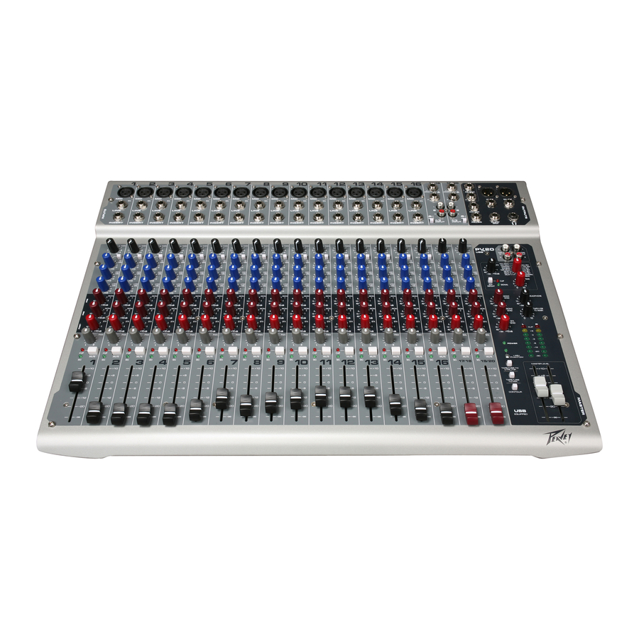
- Página 1 ™ ™ ™ 10 • PV 14 • PV Compact Mixer Operating Manual www.peavey.com...
- Página 2 ATTENTION: Afin de réduire le risque de choc électrique, ne pas enlever le couvercle. Il ne se trouve à l’intérieur aucune pièce pouvant être reparée par l’utilisateur. Confiez I’entretien et la réparation de l’appareil à un réparateur Peavey agréé. AVIS: Dans le but de reduire les risques d’incendie ou de decharge electrique, cet appareil ne doit pas etre expose a la pluie ou a l’humidite et aucun objet rempli de liquide, tel qu’un vase, ne doit...
-
Página 3: Important Safety Instructions
IMPORTANT SAFETY INSTRUCTIONS WARNING: When using electrical products, basic cautions should always be followed, including the following: Read these instructions. Keep these instructions. Heed all warnings. Follow all instructions. Do not use this apparatus near water. Clean only with a dry cloth. Do not block any of the ventilation openings. -
Página 4: Wichtige Sicherheitshinweise
WICHTIGE SICHERHEITSHINWEISE ACHTUNG: Beim Einsatz von Elektrogeräten müssen u.a. grundlegende Vorsichtsmaßnahmen befolgt werden: Lesen Sie sich diese Anweisungen durch. Bewahren Sie diese Anweisungen auf. Beachten Sie alle Warnungen. Befolgen Sie alle Anweisungen. Setzen Sie dieses Gerät nicht in der Nähe von Wasser ein. Reinigen Sie es nur mit einem trockenen Tuch. -
Página 5: Instructions Importantes De Securite
INSTRUCTIONS IMPORTANTES DE SECURITE ATTENTION: L’utilisation de tout appareil électrique doit être soumise aux precautions d’usage incluant: Lire ces instructions. Gardez ce manuel pour de futures références. Prétez attention aux messages de précautions de ce manuel. Suivez ces instructions. N’utilisez pas cette unité proche de plans d’eau. N’utilisez qu’un tissu sec pour le nettoyage de votre unité. -
Página 6: Instrucciones Importantes Para Su Seguridad
INSTRUCCIONES IMPORTANTES PARA SU SEGURIDAD CUIDADO: Cuando use productos electrónicos, debe tomar precauciones básicas, incluyendo las siguientes: Lea estas instrucciones. Guarde estas instrucciones. Haga caso de todos los consejos. Siga todas las instrucciones. No usar este aparato cerca del agua. Limpiar solamente con una tela seca. - Página 7 ENGLISH 10, PV 14 and PV ™ ™ ™ Compact Mixers Congratulations on purchasing the Peavey PV ™ 10, PV ™ 14, or the PV ™ 20 Compact Mixer. The PV ™ 10, PV ™ 14, and PV ™ 20 are studio-quality mixing consoles designed to meet diverse needs while occupying a small space.
-
Página 8: Front Panel
Front Panel Gain This control establishes the nominal operating level for the channel. GAIN The input gain can be adjusted over a wide range to compensate for soft voices or very loud drums. To maximize the signal-to-noise ratio, the gain 80 HZ should be set to the proper level, with the channel Fader (12) set to 0. - Página 9 Front Panel Signal LED The signal LED lights when the channel level reaches approxi- mately -20 dBu. This not only indicates which channels are PV20 active, but also serves as a mini level meter. TAPE TAPE Fader The channel Fader is the channel output control, which sets VOC ENH2 HALL REV VOC ENH1...
- Página 10 Front Panel EFX Time This control adjusts the time of the particular reverb or delay. Green Signal LED and Red Clip LED The green Signal LED and red Clip LED are used to set the operating input level to the PV™10, PV™14, and PV™20 effects processors.
-
Página 11: Rear Panel
Front Panel Phantom Power Switch This Switch applies +48 VDC voltage to the input XLR connectors to power microphones requiring phan- tom power. If phantom power is used, do not connect unbalanced dynamic microphones or other devices to the XLR inputs. - Página 12 Rear Panel Insert The 1⁄4” TRS connectors allow external signal processors to be inserted into the channel signal path. Tip=Send; Ring=Return; Sleeve=Ground. Stereo (1⁄4”) Inputs These 1⁄4” unbalanced inputs work as a stereo line input using both jacks or as a mono input if the con- nection is made to the left/mono input only.
-
Página 13: Power Switch
2 - POSITIVE SLEEVE = GND 3 - NEGATIVE (GND) peavey.com POWER DIGITAL AUDIO PORT A PRODUCT OF PEAVEY ELECTRONICS CORP. DESIGNED IN USA MADE IN CHINA 100 - 240V 50/60Hz COMPUTER RECORD 27 WATTS LEVEL Power Switch Depressing the power switch supplies power to the unit. - Página 14 ™ ™ ™ Block Diagram-PV 10, PV 14 & PV...
- Página 15 10, PV 14 & PV 20 Series Specifications ™ ™ ™ Inputs Input Levels Function Input Z Input Gain Bal/ Connector (ohms min) Setting Min** Nominal* Unbal Microphone 2.2k Max Gain -76 dBu -56 dBu -38 dBu XLR Pin 1 Gnd (150 ohms) (60 dB) Pin 2 (+)
- Página 16 10, PV 14, & PV 20 Specifications ™ ™ ™ Frequency Response Mic Input to Left/Right Output 14 Hz to 25 kHz +0 dB/-1 dB Total Harmonic Distortion <0.02% 20 Hz to 20 kHz Mic to Left/Right Output (10 Hz to 80 kHz BW) <0.005% Typical (22 Hz to 22 kHz BW) <0.0007% Mic Pre-amp Distortion...
- Página 17 Por favor lea esta guía cuidadosamente para asegurar tanto su seguridad personal como la de su equipo. Características • Seis entradas de micro XLR en la PV 10, diez entradas de micro XLR en la PV™14 y diez y seis en la PV™20 •Dos canales estéreo con entradas RCA y jack 1/4”...
-
Página 18: Panel Frontal
Panel Frontal Ganancia Este control establece el nivel nominal de operación del canal. La ganan- GAIN cia de entrada puede ser ajustada entre un rango muy amplio para com- pensar voces muy suaves o baterías muy altas. Para maximizar la relación 80 HZ señal-ruido, la ganancia debería ser ajustada al nivel apropiado, con el (dB) -
Página 19: Descripción
Panel Frontal LED de Saturación/Muteado Este piloto luminoso no sólo se ilumina cuando la señal del canal se está acercando al punto de saturación, sino también PV20 cuando el Muteado está conectado. El circuito indicador de TAPE TAPE saturación monitoriza la señal en diversos puntos del canal para asegurar que no hay ningún tipo de saturación. - Página 20 Panel Frontal Tiempo de Efecto Este control ajusta la duración de la reverb o el retardo seleccionado. LED verde de señal y LED rojo de saturación El LED verde de señal y el LED rojo de saturación se usan para ajustar los niveles de entrada a los proc- esadores de efectos de la PV™10, PV™14, y PV™20.
- Página 21 Panel Frontal Conmutador de Alimentación Phantom Proporciona corriente +48 VDC a las entradas XLR para alimentar a los micrófonos que requieran alimen- tación Phantom. Si usa la alimentación Phantom, no conecte micrófonos dinámicos no balanceados o otros el- ementos a las entradas XLR. Cinta a CTRL/AURICULARES Al desconectar este conmutador se añade el retorno de cinta a las salidas de Control Room (38) y Au- riculares (40) para una monitorización con latencia cero.
-
Página 22: Inserción
Conmutador A/B El selector de entrada A/B aumenta las posibilidades de la PV 10 y la PV 14 para permitir que se conec- ten dos fuentes estéreo a cada entrada de línea estéreo. Sin tener que recablear, el conmutador selec- ciona qué... - Página 23 2 - POSITIVE SLEEVE = GND 3 - NEGATIVE (GND) peavey.com DIGITAL AUDIO POWER PORT A PRODUCT OF PEAVEY ELECTRONICS CORP. DESIGNED IN USA MADE IN CHINA 100 - 240V 50/60Hz COMPUTER 27 WATTS RECORD LEVEL Conmutador de Alimentación (Power Switch) (41) Al conectar el conmutador, se le suministra corriente a la unidad.
- Página 24 ™ ™ ™ Block Diagram-PV 10, PV 14 & PV Zumbido y Ruido Características y especificaciones sujetas a cambio sin previo aviso.
-
Página 25: Especificaciones
Consolas Compactas PV 10, PV 14 & PV 20 Especificaciones ™ ™ ™ Entradas Nivel de Entrada Función Input Z Bal/ Connector Entrada Ganancia (ohms min) Min** Nominal* Desbal Setting Micrófono 2.2k Ganancia Max -76 dBu -56 dBu -38 dBu XLR Pin 1 Gnd (150 Ohms) (60 dB) - Página 26 10, PV 14, & PV 20 Especificaciones ™ ™ ™ Respuesta en Frecuencia Entrada Mic a Izq/Dcha 14 Hz to 25 kHz +0 dB/-1 dB Distorsión Armónica Total <0.02% 20 Hz to 20 kHz Micr a Izq/Salida Dcha (10 Hz to 80 kHz BW) <0.005% Tipical (22 Hz to 22 kHz BW) <0.0007% Mic Pre-amp Distorción...
- Página 27 Console de Mixage Compacte Félicitations pour l’achat de la Peavey PV10, PV14, unité de mixage au format table. Les PV10 et PV14 sont idéales pour toutes applications d’enregistrement ou de diffusion où la compacité du matériel est importante. Un processeur d’effet intégré leur permet de s’accomoder de la plupart des demandes de sonorisation.
-
Página 28: Panneau Avant
panneau avant Gain Ce contrôle vous permet d’ajuster la sensibilité d’entrée du canal cor- GAIN respondant, celui-ci pouvant s’accommoder de la plupart des types de signaux. Pour maximiser la qualité du signal, le niveau de celui-ci dans le 80 HZ canal doit être fait avec le niveau de sortie ajusté... - Página 29 panneau avant Signal LED Ces LED vous indiquent si le canal correspondant recoit un signal de niveau supérieur à -20 dBur. PV20 TAPE TAPE Fader Ce contrôle vous permet d’ajuster le niveau du signal de sortie. Le niveau d’utilisation commun (gain unitaire) est en VOC ENH 2 VOC ENH1 HALL REV...
- Página 30 panneau avant EFX Time Ce contrôle vous permet d’ajuster l’effet sélectionné. Green Signal LED and Red Clip LED Ces deux LED vous permettent de contrôler le niveau du signal à l’entrée du processeur d’effets de votre unité. Le niveau de ce signal est affecté par les faders des canaux, ainsi que les contrôles d’envoi d’effet et de niveau général d’envoi d’effet.
-
Página 31: Panneau Arrière
Ce potentiomètre est un moyen pratique d’ajuster le niveau de volume aux entrées Tape (13) ou USB (44). (Sur les modèles PV 10 et PV 14 le volume de l’entrée USB (44) sera définit par le niveau de sortie de l’ordinateur). - Página 32 panneau arrière Line (1⁄4”) Inputs Ce Jack 1/4” (6.35mm) symétrique (TRS) possède une impédance de 10 k Ohm (pointe positive) et vous permet de connecter une source sonore asymétrique Sa sensibilité est de –20dB comparée à l’entrée XLR. Les entrées XLR(Mic) et Jack(Line) du même canal ne devraient pas être utilisées en même temps. Insert Ce Jack 1/4”...
- Página 33 2 - POSITIVE SLEEVE = GND 3 - NEGATIVE (GND) peavey.com DIGITAL AUDIO POWER PORT A PRODUCT OF PEAVEY ELECTRONICS CORP. DESIGNED IN USA MADE IN CHINA 100 - 240V 50/60Hz COMPUTER RECORD 27 WATTS LEVEL Power Switch Cet interrupteur vous permet de mettre votre unité sous/hors tension.
- Página 34 ™ ™ ™ Block Diagram-PV 10, PV 14 & PV Les caractéristiques et spécifications peuvent être modifiés sans préavis.
- Página 35 Specifications Series PV 10, PV 14 & PV ™ ™ ™ Entrées Niveaux d’entrées Fonction Entree Z Réglage Bal/ Connecteur (ohms min) gain Min** Nominal* Non bal d’entrée Microphone 2.2k Gain Max -76 dBu -56 dBu -38 dBu XLR Pin 1 Gnd (150 ohms) (60 dB) Pin 2 (+)
- Página 36 Specifications PV 10, PV 14, & PV ™ ™ ™ Reponse en Fréquences Entrée Micro vers sorties Droite/Gauche: 14 Hz to 25 kHz +0 dB/-1 dB Distortion Harmonique Totale <0.02% 20 Hz to 20 kHz Micro vers sorties Droite/Gauche (10 Hz to 80 kHz BW) <0.005% Typique (22 Hz to 22 kHz BW) <0.0007% Distorion préampli Micro...
- Página 37 ™ Kompakt-Mischpult Beschreibung Herzlichen Glückwunsch! Sie haben gerade ein Peavey PV 10, PV 14 bzw. PV 20 Kompakt-Mischpult erworben. PV 10, PV 14 und PV 20 sind Mischpulte, die trotz ihrer geringen Maße Studioqualität liefern und die verschiedensten Anforderungen erfüllen.
- Página 38 Uhrzeigersinn ist das Signal nur im linken Kanal präsent, bei vollständiger Dre- hung im Uhrzeigersinn nur im rechten Kanal. An den Stereokanälen 5/6 und 7/8 des PV 10 bzw. 11/12 und 13/14 des PV 14 fungiert dieser Regler als Ausgleichsregler, mit dem der relative Pegel der Signale links und rechts eingestellt wird.
- Página 39 Vorderseite Clip/Mute-LED Diese LED zeigt in der Regel an, dass sich der Kanalsignalpe- gel dem Überlastungspunkt nähert, leuchtet jedoch auch PV20 bei eingeschalteter Mute-Taste. Die Clip-Anzeigeschaltung TAPE TAPE überwacht das Signal an vielen Punkten im Kanal um zu gewährleisten, dass sämtliche Clipping-Situationen erfasst werden.
- Página 40 Mit der grünen Signal-LED und der roten Clip-LED wird der Betriebseingangspegel zu den Effekt- prozessoren des PV 10 bzw. PV 14 eingestellt. Der Signalpegel zum Prozessor wird von den Kanal-Fader-, Effects-Send- und Effects-Send-Master-Reglern beeinflusst. Stellen Sie zuerst den Master-Regler auf 0 (12 Uhr), und stellen Sie die Kanal-Sends so ein, dass die Signal-LED leuchtet und die Clip-LED –...
- Página 41 Tape/USB to Main - nur PV 20 Dieser Knopf erlaubt in einfacher Weise die Regelung der Tape Input (13) oder USB Input (44) Lautstärke (Bei den Modellen PV 10 und PV 14 erfolgt die Steuerung der USB Lautstärke über den Computer) Contour-Schalter Ist dieser Schalter aktiviert, wird das Signal durch Hinzufügen von Bässen und Höhen verstärkt.
- Página 42 Eingangswahlschalter auf „B“ stehen. A/B-Schalter Der A/B-Eingangswahlschalter erweitert die Fähigkeiten des PV 10- bzw. PV 14-Mischpults, da zwei Stereoquellen an jeden Stereo-Line-Eingang angeschlossen werden können. Anstatt sie nochmals an- schließen zu müssen, kann mit dem Schalter ausgewählt werden, welche Eingangsklinken aktiv sind.
- Página 43 2 - POSITIVE SLEEVE = GND 3 - NEGATIVE (GND) peavey.com DIGITAL AUDIO POWER PORT A PRODUCT OF PEAVEY ELECTRONICS CORP. DESIGNED IN USA MADE IN CHINA 100 - 240V 50/60Hz COMPUTER RECORD 27 WATTS LEVEL Power-Schalter Durch Drücken dieses Schalters wird das Gerät mit Netzstrom versorgt.
- Página 44 ™ ™ ™ Block Diagram-PV 10, PV 14 & PV Änderungen von Merkmalen und technischen Daten vorbehalten.
- Página 45 10, PV 14 und PV 20 Series Technische Daten ™ ™ ™ Eingänge Eingangspegel Funktion Sym/ Stecker Eingangsimpedanz Eingangs-Gain- (ohms mind.) Einstellung Min** Nominal* Unsym Mikrofon 2.2k Max Gain -76 dBu -56 dBu -38 dBu XLR-Stift 1 Erde (150 ohms) (60 dB) Stift 2 (+) Stift 3 (-)
- Página 46 10, PV 14, & PV 20 Technische Daten ™ ™ ™ Frequenzverhalten Mic-Eingang an Left/Right-Ausgang 14 Hz to 25 kHz +0 dB/-1 dB Nichtlineare Gesamtverzerrung <0.02% 20 Hz to 20 kHz Mic an Left/Right-Ausgang (10 Hz to 80 kHz BW) <0.005% typisch (22 Hz to 22 kHz BW) <0.0007% Mic-Vorverstärkerverzerrung...
- Página 47 What Peavey Will Do We will repair or replace (at Peavey's discretion) products covered by warranty at no charge for labor or materials. If the product or component must be shipped to Peavey for warranty service, the consumer must pay initial shipping charges. If the repairs are covered by warranty, Peavey will pay the return shipping charges.
- Página 48 Features and specifications subject to change without notice. Peavey Electronics Corporation • 711 A Street • Meridian, MS 39301 (601) 483-5365 • FAX (601) 486-1278 • www.peavey.com © 2005 EX000030...