Tabla de contenido
Publicidad
Idiomas disponibles
Idiomas disponibles
Enlaces rápidos
UK
Manual user instructions.
Manuale
istruzioni per l'uso
SP
Manual de instrucciones de uso.
FR
Manuel d'instructions pour
l'utilisation.
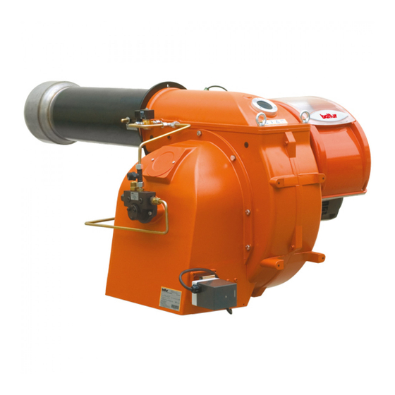
BT 250 DSG 4T
BT 300 DSG 4T
- Bruciatori di gasolio bistadio
- Two stage diesel burners
- Quemadores de gas de dos etapas
- Brûleurs de fioul à deux allures
- Heizöl-Brenner zweistufig
ISTRUZIONI ORIGINALI (IT)
ORIGINAL INSTRUCTIONS (IT)
INSTRUCCIONES ORIGINALES (IT)
ISTRUCTIONS ORIGINALES (IT)
ORIGINAL BEDIENUNGSANLEITUNG IN (IT)
DE
Bedienungsanleitung
0006081081_201406
Publicidad
Capítulos
Tabla de contenido

Manuales relacionados para baltur BT 250 DSG 4T


Resumen de contenidos para baltur BT 250 DSG 4T
- Página 1 Manuel d’instructions pour Bedienungsanleitung l’utilisation. Manuale istruzioni per l'uso BT 250 DSG 4T BT 300 DSG 4T - Bruciatori di gasolio bistadio - Two stage diesel burners - Quemadores de gas de dos etapas - Brûleurs de fioul à deux allures - Heizöl-Brenner zweistufig...
-
Página 3: Dichiarazione Di Conformità
• Prima di iniziare a usare il bruciatore leggere attentamente quanto esposto nell’opuscolo “AVVERTENZE PER L’UTENTE, PER L’USO IN SICUREZZA DEL BRUCIATORE” presente a corredo del manuale istruzioni, che costituisce parte integrante ed essenziale del prodotto. • Leggere attentamente le istruzioni prima di mettere in funzione il bruciatore o di eseguire la manutenzione. •... -
Página 4: Tabla De Contenido
SOMMARIO CARATTERISTICHE TECNICHE ..................................... 5 PREMESSE PER UNA BUONA INSTALLAZIONE ................................7 APPLICAZIONE DEL BRUCIATORE ALLA CALDAIA ..............................7 COLLEGAMENTI ELETTRICI ......................................8 TUBAZIONE DEL COMBUSTIBILE (GASOLIO) ................................9 USO DEL BRUCIATORE ........................................12 DESCRIZIONE DEL FUNZIONAMENTO DEI BRUCIATORI A DUE FIAMME ........................ 12 DESCRIZIONE DEL FUNZIONAMENTO (N°... -
Página 5: Avvertenze Per L'uso In Condizioni Di Sicurezza
L’eventuale riparazione dei prodotti dovrà essere effettuata solamente incombusti nocivi o inquinanti oltre i limiti consentiti dalle norme vigenti. da un centro di assistenza autorizzato dalla BALTUR utilizzando d) Verifi care la funzionalità dei dispositivi di regolazione e di sicurezza. -
Página 6: Alimentazione Elettrica
ALIMENTAZIONE ELETTRICA - b) la regolazione della portata del combustibile secondo la potenza • La sicurezza elettrica dell’apparecchio è raggiunta soltanto quando lo richiesta al bruciatore; stesso è corretamente collegato a un’efficace impianto di messa a terra, - c) che il bruciatore sia alimentato dal tipo di combustibile per il quale eseguito come previsto dalle vigenti norme di sicurezza. -
Página 7: Caratteristiche Tecniche
CARATTERISTICHE TECNICHE BT 250 DSG-4T BT 300 DSG-4T Kg/h PORTATA MAX Kg/h POTENZA TERMICA 1304 3186 3854 VISCOSITA’ COMBUSTIBILE GASOLIO / LIGHT OIL GASÓLEO / 1,5°E - 20°C FUEL HEIZÖL MOTORE VENTOLA 50Hz 7,5 kW - 2800 r.p.m. TRASFORMATORE 14 kV - 30mA VOLT 230V - 50Hz TENSIONE... - Página 8 1) Testa di combustione 8) Motore ventola 2) Guarnizione isolante 9) Fotoresistenza 3) Flangia fissaggio bruciatore 10) Pompa 4) Vite regolazione testa di combustione 11) Trasformatore d’accensione 5) Elettrovalvola 1° stadio normalmente 12) Elettrovalvola 2° stadio normalmente chiusa aperta 6) Servomotore regolazione aria 7) Quadro elettrico MIN - MAX MIN - MAX...
-
Página 9: Premesse Per Una Buona Installazione
che la testa di combustione è studiata per ugelli con angolo PREMESSE PER UNA di spruzzo di 45°. Solo in casi eccezionali potranno essere BUONA INSTALLAZIONE montati ugelli con angolo di spruzzo diverso, nel qual caso occorrerà accertarsi che l’ugello con angolo di spruzzo diverso non provochi inconvenienti (distacco di fiamma, imbrattamento Prima di procedere all’installazione occorre accertarsi che: del disco o della testa di combustione, accensioni violente ecc.). -
Página 10: Collegamenti Elettrici
COLLEGAMENTI ELETTRICI La linea di alimentazione trifase deve essere provvista di interruttore con fusibili. E’ inoltre richiesto dalle Norme un interruttore sulla linea di alimentazione del bruciatore, posto all’esterno del locale caldaia in posizione facilmente raggiungibile. Per i collegamenti elettrici (linea e termostati) attenersi allo schema elettrico allegato. -
Página 11: Tubazione Del Combustibile (Gasolio)
POMPA BALTUR MODELLO 300 ÷ 700 /HP TUBAZIONE DEL COMBUSTIBILE (GASOLIO) L’esposizione che segue tiene esclusivamente conto di quanto necessario per assicurare un buon funzionamento. L’apparecchio è dotato di pompa auto-aspirante capace quindi di aspirare direttamente il gasolio dalla cisterna anche per il primo riempimento. - Página 12 TABELLA TUBAZIONI PER BRUCIATORI MODELLO BT 250 DSG-4T IMPIANTO DI ALIMENTAZIONE PER GRAVITÀ Serbatoio H metri L Complessiva metri Tubazione di alimentazione Ø i=16 mm Ø i=18mm Filtro a rete Pompa Degasificatore Tubo di aspirazione Tubo ritorno bruciatore ASSE POMPA D i s p o s i t i v o a u t o m a t i c o intercettazione a bruciatore fermo...
- Página 13 TABELLA TUBAZIONI PER BRUCIATORE MODELLO BT 300 DSG-4T IMPIANTO DI ALIMENTAZIONE PER GRAVITÀ 1 Serbatoio H metri L Complessiva metri 2 Tubazione di alimentazione Ø = 3/4" Øi. 20 mm 3 Filtro a rete 4 Pompa 5 Degasificatore 6 Tubo di aspirazione 7 Tubo ritorno bruciatore ASSE POMPA 8 D i s p o s i t i v o a u t o m a t i c o...
-
Página 14: Uso Del Bruciatore
SCHEMA IDRAULICO DI PRINCIPIO ALIMENTAZIONE PER PIÚ BRUCIATORI DI GASOLIO CON VISCOSITÁ NOMINALE MASSIMA (5 °E A 50 °C) 1 - Cisterna principale 2 - Filtro 3 - Pompa di circolazione 4 - Scarico acqua ed impianto 5 - Scarico aria-gas normalmente chiusa 6 - Recupero combustibile e degasatore 7 - Valvola unidirezionale... -
Página 15: Descrizione Del Funzionamento (N° 0002901440)
DESCRIZIONE DEL valore della temperatura o pressione si è abbassata della quantità necessaria. Se, per un qualsiasi motivo, durante il funzionamento FUNZIONAMENTO (N° 0002901440) viene a mancare la fiamma, interviene immediatamente (un secondo) la fotoresistenza che, interrompendo l’alimentazione del Chiudendo l’interruttore generale sull’apparecchiatura (1) se i relè... -
Página 16: Schema Di Principio Circuito Idraulico
SCHEMA DI PRINCIPIO CIRCUITO IDRAULICO VISTA FRONTALE ugello 1° stadio valvola normalmente aperta 1° stadio ugello 2° stadio valvola normalmente chiusa 2° stadio gruppo polverizzatore porta ugelli con dispositivo chiusura pompa (tarata 16 bar) regolabile ritorno dispositivo chiusura ugello 1° stadio (tarato 12 bar) 10 aspirazione 4/1 dispositivo chiusura ugello 2°... -
Página 17: Accensione E Regolazione
ACCENSIONE E REGOLAZIONE • Con l’apparecchio così in funzione con la 2° fiamma, si provvede a regolare (vedi BT 8563/1) l’aria nella quantità necessaria per assicurare una buona combustione. • Togliere, se già esistente, il collegamento del termostato per impedire l’inserzione del 2° stadio. REGOLAZIONE DISTANZA TRA DISCO E UGELLO •... -
Página 18: Regolazione Dell'aria Sulla Testa Di Combustione
REGOLAZIONE DELL’ARIA SULLA a correggere la posizione del dispositivo che chiude l’aria sulla testa di combustione, spostando in avanti o indietro, in modo di avere un TESTA DI COMBUSTIONE flusso d’aria adeguato all’erogazione, con serranda di regolazione dell’aria in aspirazione sensibilmente aperta. La testa di combustione è... -
Página 19: Servomotore Regolazione Aria Sqn 30.111 A3500
SERVOMOTORE REGOLAZIONE ARIA SQN 30.111 A3500 PREVENTILAZIONE CON ARIA APERTA (POSIZIONE 2° STADIO) ARIA CHIUSA CON BRUCIATORE FERMO Perno di esclusione accoppiamento motore-albero cammes. Premendo si ottiene la disinserzione del collegamento motore e albero a camme. CAMMA inserzione valvola 2° stadio (deve essere regolata in posizione intermedia tra la camma di 1°... -
Página 20: Manutenzione
REGOLAZIONE CAMME SERVOMOTORE SQM10 INDICE DI RIFERIMENTO ALBERO CAMME CAMME REGOLABILI LEVA DI INSERZIONE ED ESCLUSIONE ACCOPPIAMENTO MOTORE-ALBERO CAMME (1-ESCLUSO 2-INCLUSO) Per modificare la regolazione delle camme utilizzate si agisce CAMMA REGOLAZIONE ARIA 2° FIAMMA (60°) sui risoettivi anelli (I - II - II - ...) di colore rosso. Lindice CHIUSURA TOTALE ARIA (BRUCIATORE FERMO) (0°) dell'anello rosso sulla rispettiva scala di riferimento l'angolo di rotazione impostato per ogni camma... - Página 21 TABELLA PORTATA UGELLI PER GASOLIO Ugello Pressione pompa Ugello G.P.H. Portata all’uscita dell’ugello G.P.H. 0,40 1,27 1,36 1,44 1,52 1,59 1,67 1,73 1,80 1,86 1,92 1,98 2,04 2,10 2,15 2,20 0,40 0,50 1,59 1,70 1,80 1,90 1,99 2,08 2,17 2,25 2,33 2,40 2,48...
-
Página 22: Istruzioni Per La Determinazione Delle Cause Di Irregolarita Nel Funzionamento E Loro Eliminazione
ISTRUZIONI PER LA DETERMINAZIONE DELLE CAUSE DI IRREGOLARITA NEL FUNZIONAMENTO E LORO ELIMINAZIONE NATURA IRREGOLARITÁ CAUSA POSSIBILE RIMEDIO L ’ a p p a r e c c h i o v a i n • Fotoresistenza interrotta o sporca di fumo •... - Página 23 Bruciatore che non parte • Termostati (caldaia o ambiente) o pressostati, • Alzarne il valore o attendere che si chiudano aperti per diminuzione naturale della temperatura o pressione • Fotoresistenza in corto circuito • Sostituirla • Manca la tensione per interruttore generale aperto o interruttore di massima del contatore scattato o •...
-
Página 24: Schema Elettrico
SCHEMA ELETTRICO 22 / 26 0006081081_201406... - Página 25 SIGLA APPARECCHIATURA FOTORESISTENZA / ELETTRODO DI IONIZZAZIONE RELE’ TERMICO VENTOLA RELE' TERMICO POMPA SPIA DI FUNZIONAMENTO SPIA DI BLOCCO RELE' AUSILIARIO CONTATTORE MOTORE VENTOLA CONTATTORE MOTORE POMPA MOTORE VENTOLA MOTORE POMPA PRESSOSTATO ARIA INTERRUTTORE MARCIA ARRESTO PULSANTE SBLOCCO INTERRUTTORE 1° - 2° STADIO TERMOSTATO 2 STADIO TRASFORMATORE D'ACCENSIONE TERMOSTATO CALDAIA...
- Página 26 SCHEMA ELETTRICO 24 / 26 0006081081_201406...
- Página 27 SIGLA DIN / IEC GNYE VERDE / GIALLO APPARECCHIATURA FOTORESISTENZA / ELETTRODO DI IONIZZAZIONE RELE’ TERMICO BRUNO FU1..3 FUSIBILI NERO LAMPADA FUNZIONAMENTO RESISTENZE AUSILIARIE CONNETTORE NERO CON SOVRASTAMPA SPIA DI FUNZIONAMENTO SPIA FUNZIONAMENTO VENTILATORE SPIA FUNZIONAMENTO 2° STADIO SPIA FUNZIONAMENTO VENTILATORE SPIA DI BLOCCO SPIA FUNZIONAMENTO TRASFORMATORE RELE’...
- Página 28 26 / 26 0006081081_201406...
- Página 29 • Before using the burner for the first time please carefully read the chapter “WARNINGS NOTES FOR THE USER: HOW TO USE THE BURNER SAFELY” in this instruction manual, which is an integral and essential part of the product. • Carefully read the instructions before starting or maintaining the burner.
- Página 30 TECHNICAL DATA ........................................... 5 CONDITIONS FOR CORRECT INSTALLATION ................................7 BURNER CONNECTION TO THE BOILER ..................................7 ELECTRICAL CONNECTIONS ......................................8 FUEL PIPELINES (DIESEL) ......................................9 BURNER USE ..........................................10 DESCRIPTION OF THE TWO-STAGE BURNER OPERATION ............................10 DESCRIPTION OF OPERATION (NO. 0002901440) ..............................11 BURNER USE ..........................................
- Página 31 In such case get in touch with only qualifi ed technicians. Any c) Carry out a check on combustion to ensure the production of no- product repairs must only be carried out by BALTUR authorised assi- xious or polluting unburnt gases does not exceed limits permitted stance centres using only original spare parts.
-
Página 32: Electrical Supply
ELECTRICAL SUPPLY • Have qualifi ed technicians check the following: • The equipment is electrically safe only when it is correctly connected to an a) that the feed line and the train comply with current law and regulations. effi cient ground connection carried out in accordance with current safety b) that all the gas connections are properly sealed. -
Página 33: Technical Data
TECHNICAL DATA BT 250 DSG-4T BT 300 DSG-4T MIN Kg/h FLOW RATE MAX Kg/h THERMAL CAPACITY MIN kW 1304 MAX kW 3186 3854 FUEL VISCOSITY GASOLIO / LIGHT OIL GASÓLEO / 1.5°E - 20°C FUEL HEIZÖL FAN MOTOR 50Hz 7.5 kW - 2800 r.p.m. IGNITION TRANSFORMER 14 kV - 30mA VOLT... - Página 34 1) Combustion head 9) photocell 2) Insulating gasket 10) Pump 3) Burner coupling flange 11) Ignition transformer 4) Combustion head adjustment knob 12 2nd stage solenoid valve (normally closed) 1st stage solenoid valve (normally open) 6) Air adjustment servomotor 7) Electrical panel 8) Fan motor MIN - MAX MIN - MAX...
-
Página 35: Conditions For Correct Installation
with a different spray angle will not cause any problems (flame CONDITIONS FOR CORRECT separation, disc or combustion head fouling, violent ignition, INSTALLATION etc.). • When removing the protective plastic cap from the nozzle seat Before proceeding with the installation make certain that: be careful because if the sealing surface is indented (a slight •... -
Página 36: Electrical Connections
ELECTRICAL CONNECTIONS The three-phase power supply line must have a switch with fuses. The regulations further require a switch on the burner’s power supply line, outside the boiler room and in an easily accessed position. For the electrical connections (line and thermostats), follow the wiring diagram enclosed. -
Página 37: Fuel Pipelines (Diesel)
BALTUR PUMP - 300 ÷ 700 /HP MODEL FUEL PIPELINES (DIESEL) The following description covers merely the basic requirements for an efficient operation. The unit is equipped with a self-suction pump, capable of drawing oil directly from the tank also for the first fill-up. - Página 38 PIPELINE TABLE FOR BURNERS MODEL BT 250 DSG-4T GRAVITY FEED SYSTEM Tank L total metres metres Feeding pipe Ø i = 16 mm Øi. 18 mm Wire-net filter Pump Degasifier Suction pipe Burner return pipe PUMP AXIS Automatic fuel interception device at burner shut off Non-return valve Tank...
- Página 39 PIPELINE TABLE FOR BURNER MODEL BT 300 DSG-4T GRAVITY FEED SYSTEM Tank L total metres metres Feeding pipe Ø i= 3/4" Øi. 20 mm Wire-net filter Pump Degasifier Suction pipe Burner return pipe PUMP AXIS Automatic fuel interception device at burner shut off Non-return valve SIPHON FEED SYSTEM WITH FEED FROM THE TOP OF THE TANK Tank...
-
Página 40: Burner Use
HYDRAULIC DIAGRAM OF SUPPLY FOR ONE OR MORE DIESEL BURNERS WITH MAXIMUM NOMINAL VISCOSITY (5°E AT 50 °C) 1 - Main tank 2 - Filter 3 - Circulation pump 4 - Water and system outlet 5 -Air/gas outlet - normally closed 6 - Fuel and degasser recovery 7 - Non-return valve 8 - By-pass (normally closed) -
Página 41: Description Of Operation (No. 0002901440)
DESCRIPTION OF OPERATION closure devices as soon as the pressure goes below the value to which they are set. The burner has a switch (3) on the mimic panel (NO. 0002901440) for switching from stage 1 to stage 2. Closing the main switch on the equipment (1) if the thermostats (regulation and safety) permit it, the current reaches the electric control equipment that starts the motor and the ignition transformer, after a few seconds the motor causes the fan to rotate to preventilate... -
Página 42: Front View
HYDRAULIC CIRCUIT SCHEMATIC DIAGRAM FRONT VIEW 1st stage nozzle 1st stage valve (normally open) 2nd stage nozzle 2nd stage valve (normally closed) Spray nozzle unit support with adjustable closing device Pump (set at 16 bar) 1st stage nozzle closing device (calibrated at 12 bar) Return 4/1 2nd stage nozzle closing device (calibrated at 12 bar) 10 Intake... -
Página 43: Starting Up And Regulation
DISTANCE REGULATION BETWEEN STARTING UP AND REGULATION DISC AND NOZZLE • Disconnect the thermostat (if connected) to prevent 2nd stage The burners are equipped with a device that allows the distance activation. between disc and nozzle to be varied. The factory set distance •... -
Página 44: Air Regulation On The Combustion Head
AIR REGULATION ON THE it forwards or backwards so as to have a suitable air flow for the delivery, with suction air adjustment shutter sensibly open. COMBUSTION HEAD When reducing the air passage on the combustion head, make sure not to completely close it. Perfectly center the combustion head with The combustion head is provided with a regulation device that closes respect to the disc. -
Página 45: Air Regulation Servomotor Sqn 30.111 A3500
AIR REGULATION SERVOMOTOR SQN 30.111 A3500 PREVENTILATION WITH AIR OPEN (2ND STAGE POSITION) AIR CLOSED WITH STOPPED BURNER Camshaft-motor coupling exclusion pin Pressing it disconnects the motor - camshaft connection. 2nd stage valve control CAM (must be adjusted in the intermediate position between the 1st and 2nd stage cam) 1st stage air regulation CAM Air gate CAM closed with burner stopped... -
Página 46: Maintenance
CAMS REGULATION SERVOMOTOR SQM10 REFERENCE INDEX CAMSHAFT ADJUSTABLE CAMS INSERTION AND DISINSERTION LEVER MOTOR CONNECTION CAMSHAFT (1=DISINSERTION 2=INSERTION) 2nd FLAME AIR ADJUSTING CAM (60°) TOTAL AIR CLOSURE (BURNER OFF) (0°) 1st FLAME AIR ADJUSTING CAM (20°) FLAME VALVE ACTUATING CAM (40°) To modify the regulation of the cams utilized operate the respective red rings (I - II - III...) The index of the red ring indicate on the respective reference scale the rotation... -
Página 47: Nozzle Flow Rate Table For Diesel
NOZZLE FLOW RATE TABLE FOR DIESEL Nozzle Pump pressure Nozzle G.P.H. Nozzle output flow-rate G.P.H. 0.40 1.27 1.36 1.44 1.52 1.59 1.67 1.73 1.80 1.86 1.92 1.98 2.04 2.10 2.15 2.20 0.40 0.50 1.59 1.70 1.80 1.90 1.99 2.08 2.17 2.25 2.33 2.40... - Página 48 TYPE OF PROBLEM POSSIBLE CAUSE SOLUTION The burner goes to lock-out • Photoresistance severed or fouled with smoke • Clean or replace with the flame on (Red lamp on) • Insufficient draught • Check all the smoke ducts in the boiler and The trouble is in the flame in the chimney •...
- Página 49 Burner does not start • Thermostats (boiler or room) or pressure switches • Raise their settings, or wait until pressure are open or temperature values naturally decrease to close them • Photocell short-circuit • Replace it • There is no voltage because of the an open contact in the main switch or the meter overload-release, •...
-
Página 50: Wiring Diagram
WIRING DIAGRAM 22 / 26 0006081081_201406... - Página 51 SIGLA CONTROL BOX PHOTORESISTANCE THERMAL RELAY PUMP THERMAL RELAY OPERATION LIGHT LOCK-OUT SIGNAL LAMP AUXILIARY RELAY FAN MOTOR CONTACTOR PUMP MOTOR CONTACTOR FAN MOTOR PUMP MOTOR AIR PRESSURE SWITCH ON - OFF SWITCH CONTROL BOX RESET 1° - 2° STAGE SWITCH 2°...
- Página 52 WIRING DIAGRAM 24 / 26 0006081081_201406...
- Página 53 ABBREVIATION DIN / IEC GNYE GREEN/YELLOW EQUIPMENT PHOTORESISTOR / IONIZATION ELECTRODE BLUE THERMAL CUTOUT BROWN FU1..3 FUSES BLACK AUXILIARY RESISTANCES LAMP BLACK CONNECTOR WITH OVERPRINT EN A1 OPERATION WARNING LIGHT CONTROL BOX B1 VENTILATOR LAMP 2ND STAGE LAMP VENTILATOR LAMP LOCK WARNING LIGHT TRANSFORMER LAMP MOTOR RELAY...
- Página 54 26 / 26 0006081081_201406...
-
Página 55: Información
• Antes de empezar a usar el quemador lea detenidamente el folleto “ADVERTENCIAS DIRIGIDAS AL USUARIO PARA USAR CON SEGURIDAD EL QUEMADOR” que va con el manual de instrucciones y que constituye una parte integrante y esencial del producto. • Lea detenidamente las instrucciones antes de poner en funcionamiento el quemador y efectuar las tareas de mantenimiento. - Página 56 CARACTIRÍSTICAS TÉCNICAS ...................................... 5 INFORMACIÓN PRELIMINAR PARA REALIZAR UNA INSTALACIÓN CORRECTA ...................... 7 FIJACIÓN DEL QUEMADOR A LA CALDERA ................................. 7 CONEXIONES ELÉCTRICAS ......................................8 TUBERÍA DEL COMBUSTIBLE (GASÓLEO)................................... 9 USO DEL QUEMADOR ........................................12 DESCRIPCIÓN DEL FUNCIONAMIENTO DE LOS QUEMADORES DE DOS ETAPAS ....................12 DESCRIPCIÓN DEL FUNCIONAMIENTO (N°...
-
Página 57: Advertencias Para El Uso En Condiciones De Seguridad
La eventual reparación de los aparatos tiene que hacerla solamente un d) Comprobar que funcionen bien los dispositivos de regulación y centro de asistencia autorizado por BALTUR utilizando exclusivamente seguridad. repuestos originales. Si no se respeta lo anteriormente se puede com- e) Comprobar que funcione correctamente el conducto de expulsión de... -
Página 58: Alimentación Eléctrica
ALIMENTACIÓN ELÉCTRICA • La primera vez que se pone en funcionamiento el aparato, el personal cualifi cado profesionalmente tiene que controlar: • La seguridad eléctrica del aparato se consigue solo cuando el mismo a) la estanqueidad en el tramo interior y exterior de los tubos de está... -
Página 59: Caractirísticas Técnicas
CARACTIRÍSTICAS TÉCNICAS BT 250 DSG-4T BT 300 DSG-4T MÍN Kg/h CAUDAL MÁX Kg/h POTENCIA TÉRMICA MÍN. kW 1304 MÁX. kW 3186 3854 VISCOSIDAD COMBUSTIBLE GASOLIO / LIGHT OIL GASÓLEO / 1,5°E - 20°C FUEL HEIZÖL MOTOR DEL VENTILADOR 50Hz 7,5 kW - 2800 r.p.m. TRANSFORMADOR 14 kV - 30mA VOLTIOS... - Página 60 1) Cabezal de combustión 7) Cuadro eléctrico 2) Junta aislante 8) Motor del ventilador 3) Brida de fijación del quemador Fotorresistencia 4) Tornillo de regulación cabezal de 10 Bomba combustión 11) Transformador de encendido 5) Electroválvula 1 etapa (normalmente 12 Electroválvula 2 etapa (normalmente cerrada) abierta) 6) Servomotor de regulación del aire...
-
Página 61: Información Preliminar Para Realizar Una Instalación Correcta
por la caldera y admitida por el quemador. Es importante recordar INFORMACIÓN PRELIMINAR que el cabezal de combustión ha sido diseñado para boquillas PARA REALIZAR UNA con ángulo de rociado de 45°. Sólo en casos extraordinarios se INSTALACIÓN CORRECTA podrán usar boquillas con ángulo de rociado diferente, pero no sin antes comprobar que dichas boquillas diferentes no causen inconvenientes (desprendimiento de llama, ensuciamiento del Antes de proceder a efectuar la instalación es necesario asegurarse... -
Página 62: Conexiones Eléctricas
CONEXIONES ELÉCTRICAS La línea de alimentación trifásica debe contar con un interruptor de fusibles. Las Normas requieren además un interruptor en la línea de alimentación del quemador, situado en el exterior del local de la caldera en un posición a la que se pueda llegar fácilmente. Para las conexiones eléctricas (línea y termostatos) utilizar el esquema eléctrico anexo. -
Página 63: Tubería Del Combustible (Gasóleo)
BOMBA BALTUR MODELO 300 ÷ 700 /HP TUBERÍA DEL COMBUSTIBLE (GASÓLEO) A continuación sólo exponemos cuanto es necesario para garantizar el buen funcionamiento. El aparato dispone de una bomba autoaspiradora capaz de aspirar directamente el gasóleo del tanque incluso para el primer llenado. Para garantizar un buen funcionamiento es preferible que las tuberías de aspiración y de... -
Página 64: Sistema De Alimentación Por Gravedad
TABLA TUBERÍAS PARA QUEMADORES MODELO BT 250 DSG-4T SISTEMA DE ALIMENTACIÓN POR GRAVEDAD Depósito L Total metros metros Tubería de alimentación Ø i. 16 mm Øi. 18 mm Filtro de red Bomba Desgasificador Tubo de aspiración Tubo de retorno quemador EJE BOMBA Dispositivo automático de corte con el quemador parado... - Página 65 TABLA TUBERÍAS PARA QUEMADOR MODELO BT 300 DSG-4T SISTEMA DE ALIMENTACIÓN POR GRAVEDAD Depósito H metros L Total metros Tubería de alimentación Ø = 3/4" Øi. 20 mm Filtro de red Bomba Desgasificador Tubo de aspiración Tubo de retorno quemador EJE BOMBA Dispositivo automático de corte con el quemador parado...
-
Página 66: Uso Del Quemador
ESQUEMA HIDRÁULICO DE PRINCIPIO PARA LA ALIMENTACIÓN DE MÁS DE UN QUEMADOR CON UNA VISCOSIDAD NOMINAL MÁXIMA (5°E A 50°C) 1 - Cisterna principal 2 - Filtro 3 - Bomba de circulación 4 - Descarga agua y equipo 5 - Descarga aire-gas normalmente cerrada 6 - Depósito para recuperación del combustible y degasificador... -
Página 67: Descripción Del Funcionamiento (N° 0002901440)
DESCRIPCIÓN DEL El equipo vuelve a funcionar automáticamente cuando el valor de la temperatura o de la presión baja del valor necesario. Si FUNCIONAMIENTO por alguna razón durante el funcionamiento faltara la llama, se (N° 0002901440) activará inmediatamente (en un segundo) la fotorresistencia que, interrumpiendo la alimentación del relé... -
Página 68: Esquema De Principio Circuito Hidráulico
ESQUEMA DE PRINCIPIO CIRCUITO HIDRÁULICO VISTA DELANTERA boquilla 1 etapa válvula normalmente abierta 1 etapa boquilla 2 etapa válvula normalmente cerrada 2 etapa grupo pulverizador porta boquillas con dispositivo cierre bomba (calibrada 16 bares) regulable retorno dispositivo cierre boquilla 1 etapa (calibrada 12 bares) 10 aspiración 4/1 dispositivo cierre boquilla 2... -
Página 69: Encendido Y Regulación
ENCENDIDO Y REGULACIÓN • Con el aparato así en funcionamiento con la 2ª llama, se procede a regular (ver BT 8563/1) el aire en la cantidad necesaria para asegurar una buena combustión. • Si ya está presente, quitar la conexión del termostato para impedir la activación de la 2ª... -
Página 70: Regulación Del Aire En El Cabezal De Combustión
REGULACIÓN DEL AIRE EN EL la posición del dispositivo que cierra el aire en el cabezal de combustión, desplazándolo hacia adelante o atrás, para tener un CABEZAL DE COMBUSTIÓN flujo del aire adecuado al suministro con compuerta de regulación del aire en aspiración bien abierta. El cabezal de combustión cuenta con un dispositivo de regulación Reduciendo el pasaje del aire en el cabezal de combustión será... -
Página 71: Servomotor Regulación Aire Sqn 30.111 A3500
SERVOMOTOR REGULACIÓN AIRE SQN 30.111 A3500 PREVENTILACIÓN CON AIRE ABIERTO EN POSICIÓN 2° ETAPA Y AIRE CERRADO CON QUEMADOR PARADO Perno de exclusión acoplamiento motor - árbol de levas. Presionando se desactiva la conexión motor y árbol. LEVA conexión válvula 1ª etapa (se debe regular en posición intermedia entre la leva de 1ª... -
Página 72: Mantenimiento
REGLAJE LEVAS SERVOMOTOR SQM10 ÍNDICE DE REFERENCIA EJE DE LEVAS LEVAS REGULABLES PALANCA DE INSERCION Y EXCLUSION UNION MOTOR EJE DE LEVAS ( 1=EXCLUIDO 2=ACTIVADO) LEVA REGULACIÓN AIRE 2ª LLAMA (60°) Para moficar la regualacion de las levas utilizadas se opera con los respectivos antillos (I - II - III...) de color rojo. -
Página 73: Tabla Caudal Boquillas Para Gasóleo
TABLA CAUDAL BOQUILLAS PARA GASÓLEO Boquilla Presión bomba Boquilla G.P.H. Caudal a la salida de la boquilla G.P.H. 0,40 1,27 1,36 1,44 1,52 1,59 1,67 1,73 1,80 1,86 1,92 1,98 2,04 2,10 2,15 2,20 0,40 0,50 1,59 1,70 1,80 1,90 1,99 2,08 2,17... -
Página 74: Instrucciones Para Determinar Las Causas De Irregularidades En El Funcionamiento Y Posible Solución
INSTRUCCIONES PARA DETERMINAR LAS CAUSAS DE IRREGULARIDADES EN EL FUNCIONAMIENTO Y POSIBLE SOLUCIÓN TIPO DE IRREGULARIDAD POSIBLE CAUSA SOLUCIÓN El quemador se bloquea con • Fotorresistencia cortada o sucia de humo • Limpiarla o sustituirla. la llama (luz roja encendida) •... -
Página 75: Desgastado
El quemador no se enciende • Termostatos (caldera o ambiente) o presostatos • Aumentar el valor o esperar que se cierren abiertos para la disminución natural de la temperatura o de la presión • Fotorresistencia en corto circuito • Sustituirla •... -
Página 76: Esquema Eléctrico
ESQUEMA ELÉCTRICO 22 / 26 0006081081_201406... - Página 77 SIGLA DISPOSITIVO F O T O R E S I S T E N C I A / E L E T T R O D O I O N I Z A C I O N / FOTOCELULA UV RELE TERMICO IMPULSOR DE LA BOMBA RELÉ...
- Página 78 ESQUEMA ELÉCTRICO 24 / 26 0006081081_201406...
- Página 79 SIGLA DIN / IEC GNYE VERDE / AMARILLO EQUIPO FOTORESISTENCIA / ELECTRODO IONIZACION AZUL RELÉ TÉRMICO MARRÓN FU1..3 FUSIBLES NEGRO LÁMPARA DE FUNCIONAMIENTO DE LAS RESISTENCIAS CONDUCTOR NEGRO CON IMPRESIÓN AUXILIARES LUZ INDICADORA DE FUNCIONAMIENTO LUZ VENTILADOR 2DA ETAPA LUZ LUZ VENTILADOR INDICADOR DE BLOQUEO LUZ TRASFORMADOR...
- Página 80 26 / 26 0006081081_201406...
-
Página 81: Avertissements
• Avant de commencer à utiliser le brûleur, lire attentivement les recommandations de la notice « RECOMMANDATIONS A L’ATTENTION DE L’UTILISATEUR POUR UN USAGE DU BRULEUR EN TOUTE SECURITE » jointe au manuel d’instructions et qui constitue une partie intégrante et essentielle du produit. - Página 82 CARACTERISTIQUES TECHNIQUES .................................... 5 NOTES D'INTRODUCTION POUR UNE CORRECTE INSTALLATION .......................... 7 APPLICATION DU BRULEUR A LA CHAUDIERE ................................7 CONNEXIONS ELECTRIQUES ....................................... 8 TUYAUTERIE DU COMBUSTIBLE (FIOUL) ..................................9 UTILISATION DU BRULEUR ......................................12 DESCRIPTION DU FONCTIONNEMENT DES BRÛLEURS DEUX ALLURES ....................... 12 DESCRIPTION DU FONCTIONNEMENT (N.
-
Página 83: Recommandations Pour Un Usage En Toute Sécurité
é. L’éventuelle réparation des produits doit être effectuée par un d) Vérifi er le fonctionnement des dispositifs de réglage et de sécurité. centre de service après-vente agréé par BALTUR en utilisant exclusive- e) Vérifi er le fonctionnement du conduit d’évacuation des produits de la ment des pièces détachées d’origine. -
Página 84: Alimentation Electrique
ALIMENTATION ELECTRIQUE se au brûleur ; • La sécurité électrique de l’appareil est atteinte uniquement lorsque ce c) le brûleur doit être alimenté par le type de combustible pour lequel il dernier est correctement raccordé à une installation de mise à la terre est prédisposé... -
Página 85: Caracteristiques Techniques
CARACTERISTIQUES TECHNIQUES BT 250 DSG-4T BT 300 DSG-4T MIN kg/h DEBIT MAX kg/h PUISSANCE THERMIQUE 1304 3186 3854 VISCOSITÉ COMBUSTIBLE FIOUL / LIGHT OIL GASÓLEO / FUEL 1,5 °E - 20°C HEIZÖL MOTEUR VENTILATEUR 50Hz 7,5 kW / 2 800 trs/mn TRANSFORMATEUR 14 kV - 30mA VOLT... - Página 86 1) Tête de combustion 8) Moteur du ventilateur 2) Joint isolant Photorésistance 3) Bride de fixation du brûleur 10) Pompe 4) Vis de réglage tête de combustion 11) Transformateur d'allumage 5) Électrovanne 1ère allure normalement 12) Électrovanne 2ème allure normalement fermée ouverte 6) Servomoteur de réglage de l'air 7) Tableau électrique...
-
Página 87: Notes D'introduction Pour Une Correcte Installation
de pulvérisation de 45°. L'installation de gicleurs avec angle de NOTES D'INTRODUCTION POUR pulvérisation différent n'est admise qu'en cas exceptionnels ; il UNE CORRECTE INSTALLATION faudra donc s'assurer que le gicleur avec angle de pulvérisation différent n'entraîne pas d'inconvénients (détachement de la flamme, salissure du disque ou de la tête de combustion, de Avant de procéder à... -
Página 88: Connexions Electriques
CONNEXIONS ELECTRIQUES La ligne d’alimentation triphasée doit être équipée d’un interrupteur avec fusibles. De plus, les normes prévoient un interrupteur sur la ligne d’alimentation du brûleur, situé à l’extérieur du local chaudière, en position facilement accessible. Pour les raccordements électriques (ligne et thermostats) suivre le schéma électrique annexé. -
Página 89: Tuyauterie Du Combustible (Fioul)
POMPE BALTUR MODÈLE 300 ÷ 700 /HP TUYAUTERIE DU COMBUSTIBLE (FIOUL) L’illustration qui suit ne tient compte que des informations nécessaires à assurer un fonctionnement correct. L’appareil est doté d’une pompe auto-aspirante permettant d’aspirer directement le fioul depuis la cuve même pour le premier remplissage. Pour garantir un bon fonctionnement, il est conseillé... - Página 90 TABLEAU TUYAUTERIES POUR BRÛLEURS MODÈLE BT 250 DSG-4T INSTALLATION D’ALIMENTATION PAR GRAVITÉ Réservoir H mètres L Totale en mètres Tuyauterie d’alimentation Ø i = 16 Øi. 18 mm Crépine de filtration Pompe Dégazeur Tuyau d’aspiration Tuyau de retour brûleur AXE POMPE D i s p o s i t i f a u t o m a t i q u e d'interception avec brûleur à...
- Página 91 TABLEAU TUYAUTERIES POUR BRÛLEUR MODÈLE BT 300 DSG-4T INSTALLATION D’ALIMENTATION PAR GRAVITÉ 1 Réservoir L Totale en mètres mètres 2 Tuyauterie d’alimentation Ø = 3/4" Øi. 20 mm 3 Crépine de filtration 4 Pompe 5 Dégazeur 6 Tuyau d’aspiration 7 Tuyau de retour brûleur AXE POMPE 8 D i s p o s i t i f a u t o m a t i q u e d'interception avec brûleur...
-
Página 92: Utilisation Du Bruleur
SCHÉMA HYDRAULIQUE DE PRINCIPE ALIMENTATION POUR PLUSIEURS BRÛLEURS DE FIOUL À VISCOSITÉ NOMINALE MAXIMALE (5 °E À 50 °C) 1 - Citerne principale 2 - Filtre 3 - Pompe de circulation 4 - Écoulement eau et installation 5 - Évacuation air-gaz normalement fermée 6 - Récupération combustible et dégazeur... -
Página 93: Description Du Fonctionnement (N. 0002901440)
DESCRIPTION DU L'appareil se remet en fonction de manière automatique lorsque la valeur de la température ou de la pression s'est abaissée de la FONCTIONNEMENT quantité nécessaire. Si la flamme n'est pas présente, pour quelque (N. 0002901440) raison que ce soit, en cours de fonctionnement, la photorésistance s'active tout de suite (une seconde) : elle arrête l'alimentation du En fermant l’interrupteur principal sur l'appareillage (1), après relais correspondant, en permet l'ouverture et, par conséquent,... -
Página 94: Vue De Face
SCHEMA DE PRINCIPE DU CIRCUIT HYDRAULIQUE VUE DE FACE gicleur 1ère allure vanne normalement ouverte 1ère allure gicleur 2ème allure vanne normalement fermée 2ème allure groupe de pulvérisation porte-gicleurs avec dispositif de pompe (réglée 16 bars) fermeture réglable retour dispositif de fermeture gicleur 1ère allure (réglé 12 bars) 10 aspiration 4/1 dispositif de fermeture gicleur 2ème allure (réglé... -
Página 95: Allumage Et Reglage
ALLUMAGE ET REGLAGE • Avec l'appareil qui fonctionne avec la 2ème flamme, on peut régler (voir BT 8563/1) le débit d'air nécessaire à une bonne combustion. • Enlever, s'il existe, le raccordement au thermostat pour empêcher l'insertion de la deuxième flamme. RÉGLAGE DISTANCE ENTRE DISQUE ET GICLEUR •... -
Página 96: Réglage De L'air Sur La Tête De Combustion
RÉGLAGE DE L’AIR SUR LA Lorsque le débit maximal souhaité est atteint, on veille à corriger la position du dispositif qui ferme l’air sur la tête de combustion TÊTE DE COMBUSTION en le déplaçant vers l’avant ou vers l’arrière, de sorte à obtenir un flux d’air adapté... -
Página 97: Servomoteur Réglage Air Sqn 30.111 A3500
SERVOMOTEUR RÉGLAGE AIR SQN 30.111 A3500 PRÉ-VENTILATION AVEC AIR OUVERT (POSITION 2ÈME ALLURE) ET AIR FERMÉ AVEC BRÛLEUR À L'ARRÊT Axe d'exclusion accouplement moteur - arbre à cames. En appuyant on obtient la désactivation de l'accouplement moteur et arbre à cames. CAME activation vanne 2ème allure (doit être réglée en position intermédiaire entre la came de 1ère allure et la came de 2ème allure) -
Página 98: Entretien
RÉGLAGE MOTEUR « CONECTRON LKS 160 » POUR COMMANDE VOLET D'AIR 2ÈME ALLURE INDICE DE RÉFÉRENCE ARBRE CAMES CAMES RÉGLABLES LEVIER D' INSERTION ET D'ARRET ACCOUPLEMENT MOTEUR ARBRE A CAMES (1=DISINSERTION 2=ARRETE') CAME REGLAGE AIR 2ème FLAMME (60°) POUR MODIFIER LE REGLAGE DES CAMES, EMPLOYER FERMETURE TOTALE AIR (BRÛLEUR ARRÊTÉ) (0°) LES BAGUES ROUGES (I - II - III - ...) L'INDEX DE CAME REGLAGE AIR 1ère FLAMME (20°) - Página 99 TABLEAU DÉBIT GICLEURS POUR FIOUL Gicleur Pression pompe Gicleur G.P.H. Débit à la sortie du gicleur G.P.H. 0,40 1,27 1,36 1,44 1,52 1,59 1,67 1,73 1,80 1,86 1,92 1,98 2,04 2,10 2,15 2,20 0,40 0,50 1,59 1,70 1,80 1,90 1,99 2,08 2,17 2,25...
-
Página 100: Instructions Pour Établir Les Causes Des Irrégularités Dans Le Fonctionnement Et Leur Effacement
INSTRUCTIONS POUR ÉTABLIR LES CAUSES DES IRRÉGULARITÉS DANS LE FONCTIONNEMENT ET LEUR EFFACEMENT NATURE DE CAUSE POSSIBLE REMEDE L’IRREGULARITE Le brûleur se bloque avec • Photorésistance interrompue ou sale à cause de • La nettoyer ou la remplacer la flamme (lampe rouge fumée •... - Página 101 Le brûleur ne démarre pas • Thermostats (chaudière ou ambiant) ou • En augmenter la valeur ou attendre leur pressostats, ouverts fermeture due à la diminution naturelle de température ou de pression • Court-circuit de la photorésistance • La remplacer •...
- Página 102 22 / 26 0006081081_201406...
- Página 103 SIGLE APPAREILLAGE PHOTORÉSISTANCE / ÉLECTRODE D'IONISATION RELAIS THERMIQUE RELAIS TERMIQUE POMPE LAMPE MARCHE LAMPE DE BLOCAGE RELÉ AUTOMÁTICO CONTACTEUR MOTEUR VENTILATEUR CONTACTEURMOTEUR POMPE MOTEUR VENTILATEUR MOTEUR POMPE PRESSOSTAT DE L'AIR INTERRUPTEUR MARCHE / ARRÊT TOUCHE DE DEBLOCAGE INTERRUPTEUR 1ÈRE - 2ÈME ALLURE THERMOSTAT 2ÈME ALLURE TRANSFORMATEUR D'ALLUMAGE THERMOSTAT CHAUDIÈRE...
-
Página 104: Schema Electrique
SCHEMA ELECTRIQUE 24 / 26 0006081081_201406... - Página 105 SIGLE DIN / IEC GNYE VERT / JAUNE APPAREILLAGE PHOTORÉSISTANCE / ÉLECTRODE D'IONISATION BLEU RELAIS THERMIQUE MARRON FU1..3 FUSIBLES NOIR * H0 LAMPE DE FONCTIONNEMENT RÉSISTANCES AUXILIAIRES CONNECTEUR NOIR AVEC SURIMPRESSION TÉMOIN DE FONCTIONNEMENT LAMPE MOTEUR 2ME ETAGE LAMPE LAMPE MOTEUR TÉMOIN DE BLOCAGE LAMPE TRASFORMATEUR RELAIS MOTEUR...
- Página 106 26 / 26 0006081081_201406...
-
Página 107: Konformitätserklärung
• Vor Verwendung des Brenners muss der Inhalt des Merkblatts „HINWEISE FÜR DEN BEDIENER ZUR SICHEREN VERWENDUNG DES BRENNERS”, das der Bedienungsanleitung beiliegt und einen wesentlichen Teil des Produkts darstellt, aufmerksam gelesen werden. • Lesen Sie bitte diese Betriebsanleitung vor der Montage, Inbetriebnahme und Wartung sorgfältig durch. •... - Página 108 TECHNISCHE DATEN ........................................5 VORAUSSETZUNGEN FÜR EINE KORREKTE INSTALLATION ............................ 7 ANBAU DES BRENNERS AM HEIZKESSEL................................... 7 ELEKTRISCHE ANSCHLÜSSE ....................................... 8 BRENNSTOFFLEITUNGEN (HEIZÖL) .................................... 9 VERWENDUNG DES BRENNERS ....................................12 BESCHREIBUNG DER FUNKTIONSWEISE DER ZWEISTUFIGEN BRENNER ......................12 BESCHREIBUNG DER MODULIERENDEN FUNKTIONSWEISE (NR. 0002901440) ....................13 ZÜNDUNG UND REGULIERUNG ....................................
-
Página 109: Allgemeine Hinweise
Umfang, als von den geltenden Bestimmungen zugelassen ist, zu wenden. Die eventuelle Reparatur der Produkte darf nur von einem vermeiden. von BALTUR autorisierten Kundendienstzentrum unter ausschließli- d) Die Funktionalität der Regel- und Sicherheitsvorrichtungen überprüfen. cher Verwendung von Originalersatzteilen durchgeführt werden. Die e) Das einwandfreie Funktionieren der Rauchgasausleitung überprüfen. - Página 110 HINWEISE FÜR DEN BENUTZER ZUR SICHEREN BENUTZUNG DES BRENNERS VORBEMERKUNG STROMVERSORGUNG - Dichtheitskontrolle im inneren und äußeren Abschnitt der • Die elektrische Sicherheit des Geräts wird nur erreicht, wenn Brennstoffleitungen; dieses vorschriftsmäßig an eine wirksame, nach den geltenden - Einstellung des Brennstoffdurchsatzes auf die vom Brenner Sicherheitsbestimmungen ausgeführte Erdungsanlage angeschlossen verlangte Leistung;...
-
Página 111: Technische Daten
TECHNISCHE DATEN BT 250 DSG-4T BT 300 DSG-4T kg/h DURCHSATZ MAX. kg/h HEIZLEISTUNG MIN. 1304 MAX. 3186 3854 BRENNSTOFFVISKOSITÄT GASOLIO / LIGHT OIL GASÓLEO / 1,5°E - 20°C FUEL HEIZÖL GEBLÄSEMOTOR 50Hz 7,5 kW - 2800 U/min. ZÜNDTRANSFORMATOR 14 kV - 30mA VOLT 230V - 50Hz SPANNUNG... - Página 112 1) Flammkopf 8) Gebläsemotor 2) Isolierungsdichtung 9) Fotowiderstand 3) Befestigungsflansch Brenner 10) Pumpe 4) Luftregelschraube im Brennerkopf 11) Zündtransformator 5) Elektroventil 1. Stufe (normalerweise 12) Elektroventil 2. Stufe (normalerweise geöffnet) geschlossen) 6) Servomotor für Luftregulierung 7) Schalttafel MIN - MAX MIN - MAX BT 250 DSG-4T 1480...
-
Página 113: Voraussetzungen Für Eine Korrekte Installation
sein. Es wird darauf hingewiesen, dass der Brennerkopf für VORAUSSETZUNGEN FÜR EINE Düsen mit einem Sprühwinkel von 45° entwickelt wurde. Nur in KORREKTE INSTALLATION Ausnahmefällen können Düsen mit einem anderen Sprühwinkel montiert werden. In einem solchen Fall ist zu prüfen, dass die mit dem anderen Sprühwinkel ausgelegte Düse keine Störungen Vor der Installation muss sichergestellt werden, dass: verursacht (Flammenablösung, Verschmutzung der Scheibe... -
Página 114: Elektrische Anschlüsse
ELEKTRISCHE ANSCHLÜSSE Die dreiphasige Versorgungsleitung muss mit einem Trennschalter mit Sicherungen ausgerüstet sein. Außerdem verlangen die Normen einen außerhalb des Heizkesselraums in leicht zugänglicher Position anzubringenden Schalter an der Versorgungsleitung des Brenners. Für die Elektroanschlüsse (Leitung und Thermostate) siehe beiliegenden Schaltplan. Um den Anschluss des Brenners an die Versorgungsleitung auszuführen, folgendermaßen vorgehen: •... -
Página 115: Brennstoffleitungen (Heizöl)
BALTUR PUMPE MODELL 300 ÷ 700 /PS BRENNSTOFFLEITUNGEN (HEIZÖL) Die folgenden Informationen beziehen sich ausschließlich auf einen reibungslosen Betrieb. Die Vorrichtung verfügt über eine automatische Ansaugpumpe, die in der Lage ist, Öl aus dem Tank auch für die erste Füllung anzusaugen. Zur Gewährleistung eines einwandfreien Betriebs sollten die Leitungen, Ansaugleitung und Rücklauf vorzugsweise mit geschweißten Anschlussstücken... - Página 116 TABELLE - LEITUNGEN FÜR BRENNER MODELL BT 250 DSG-4T SCHWERKRAFTVERSORGUNGSANLAGE Tank H Meter Gesamt L Meter Versorgungsleitung Ø i. 16 mm Øi. 18 mm Netzfilter Pumpe Entgaser Saugleitung Rücklaufrohr Brenner PUMPENACHSE A u t o m a t i s c h e S p e r r v o r r i c h t u n g b e i stillstehendem Brenner Sperrventil...
- Página 117 TABELLE - LEITUNGEN FÜR BRENNER MODELL BT 300 DSG-4T SCHWERKRAFTVERSORGUNGSANLAGE Tank H Meter Gesamt L Meter Versorgungsleitung Ø = 3/4" Øi. 20 mm Netzfilter Pumpe Entgaser Saugleitung Rücklaufrohr Brenner PUMPENACHSE A u t o m a t i s c h e S p e r r v o r r i c h t u n g b e i stillstehendem Brenner Sperrventil...
-
Página 118: Verwendung Des Brenners
HYDRAULISCHER PRINZIPPLAN DER VERSORGUNG FÜR MEHRERE BRENNER MIT MAX. NENNVISKOSITÄT (BEI 5° UND 50 °C) 1 - Haupttank 2 - Filter 3 - Umwälzpumpe 4 - Wasser- und Anlageablass 5 - Luft-/Gasablass normalerweise geschlossen 6 - Brennstoffrückgewinnung und Entgaser 7 - Sperrventil 8 - B y - P a s s ( n o r m a l e r w e i s e geschlossen) Die Heizölgewinnungsbehälter (Durchmesser 150 mm - Höhe ~ 400 mm) müssen so nahe wie möglich... -
Página 119: Beschreibung Der Modulierenden Funktionsweise (Nr. 0002901440)
BESCHREIBUNG DER Brenner vom Fotowiderstand und den Themostaten gesteuert und überwacht. Erreicht die Temperatur oder der Druck den Wert, auf MODULIERENDEN den der Betriebsthermostat oder -druckregler geeicht sind, bewirkt FUNKTIONSWEISE ihr Auslösen die Ausschaltung des Brenners. Das Gerät schaltet sich nach der angemessenen Senkung des (NR. -
Página 120: Geräteeigenschaften
PRINZIPSCHEMA DES HYDRAULIKKREISLAUFS FRONTANSICHT Düse 1. Stufe Ventil normalerweise geöffnet 1. Stufe Düse 2. Stufe Ventil normalerweise geschlossen 2. Stufe Zerstäubergruppe Düsenhalter mit regulierbarer Pumpe (auf 16 Bar geeicht) Schließvorrichtung Rücklauf Schließvorrichtung Düse 1. Stufe (auf 12 Bar geeicht) 10 Ansaugung 4/1 Schließvorrichtung Düse 2. -
Página 121: Zündung Und Regulierung
ZÜNDUNG UND REGULIERUNG • Läuft das Gerät nun mit der 2. Flamme, muss die Luftmenge in angemessener Weise eingestellt werden (siehe BT 8563/1), um eine gute Verbrennung zu erzielen. • Falls bereits vorhanden, die Verbindung des Thermostats trennen, um ein Einschalten der 2. Stufe zu verhindern. EINSTELLUNG DES ABSTANDS •... -
Página 122: Lufteinstellung Am Brennerkopf
LUFTEINSTELLUNG AM Mit Erreichen der höchsten gewünschten Abgabe ist die Schließvorrichtung am Brennerkopf durch Vor- und Zurückstellen insofern zu korrigieren, als BRENNERKOPF dass ein an die Zufuhr angepasster Luftstrom entsteht, wobei sich die Lufteinstellklappe in einer erheblich geöffneten Stellung befinden muss. Der Brennerkopf ist mit einer Regelvorrichtung ausgerüstet, so dass der Beim Verkleinern des Luftdurchlasses am Brennerkopf muss die Luftdurchlass zwischen Scheibe und Kopf geschlossen (vorschieben) -
Página 123: Servomotor Luftregelung Sqn 30.111 A3500
SERVOMOTOR LUFTREGELUNG SQN 30.111 A3500 VORBELÜFTUNG MIT OFFENER LUFT (POSITION DER 2. STUFE) UND GESCHLOSSENER LUFT BEI STILLSTEHENDEM BRENNER Bolzen für Ausschluss der Kopplung zwischen Motor - Nockenwelle. Durch Drücken wird die Auskopplung der Verbindung zwischen Motor und Nockenwelle erlangt. NOCKEN Ventileinschaltung 2. -
Página 124: Wartung
NOCKEN REGELUNG STELLMOTOR SQM 10-20 REFERENZINDEX NOCKENWELLE REGULIERBARE NOCKEN ZAPFEN FUR DIE ENTKUPPLUNG MOTOR- NOCKNWELLE (1=ENTKUPPELT 2=EINGEKUPPELT) NOCKEN LUFTREGELUNG 2. FLAMME (60°) VOLLSTÄNDIGER LUFTZUFUHRVERSCHLUSS ZUR VERSTELLING DER ROTEN NOKEN MUB MAN AN DEN (BRENNER STEHT) (0°) ROTEN RIGEN (I - II - III - ...) DREHEN DER ZEIGER NOCKEN LUFTREGELUNG 1. - Página 125 DÜSENDURCHSATZTABELLE FÜR HEIZÖL Düse Pumpendruck Düse G.P.H. Durchsatzmenge am Düsenaustritt G.P.H. 0,40 1,27 1,36 1,44 1,52 1,59 1,67 1,73 1,80 1,86 1,92 1,98 2,04 2,10 2,15 2,20 0,40 0,50 1,59 1,70 1,80 1,90 1,99 2,08 2,17 2,25 2,33 2,40 2,48 2,55 2,62 2,69...
-
Página 126: Anleitungen Zur Bestimmung Der Ursachen Von Betriebsstörungen Und Ihre Behebung
ANLEITUNGEN ZUR BESTIMMUNG DER URSACHEN VON BETRIEBSSTÖRUNGEN UND IHRE BEHEBUNG ART DER STÖRUNG MÖGLICHE URSACHE ABHILFE Das Gerät blockiert mit • Fotowiderstand unterbrochen oder durch Rauch • Reinigen oder austauschen. F l a m m e ( r o t e L e u c h t e verschmutzt •... - Página 127 Der Brenner startet nicht • Thermostate (Heizkessel oder Umgebung) oder • Wert erhöhen oder abwarten, dass sie sich Druckregler offen aufgrund der natürlichen Temperatur- oder Druckabnahme schließen • Fotowiderstand in Kurzschluss • Austauschen • Es fehlt die Spannung für den offenen Hauptschalter oder der Schutzschalter des Kontakts hat ausgelöst •...
- Página 128 22 / 26 0006081081_201406...
- Página 129 ZEICHEN GERÄT FOTOWIDERSTAND / IONISATIONSELEKTRODE THERMISCHES RELAIS THERMISCHES RELAIS PUMPENMOTOR BETRIEBSLAMPE BLOCKKONTROLLLAMPE HILFSRELAY MOTOR RELAIS EXTERNES SCHÜTZ MOTOR PUMPU MOTOR LUFTDRUCKWAECHTER EIN AUS SCHALTER ENTSPERRKNOPF SCHALTER 1. - 2. STUFE THERMOSTAT 2. STUFE ZÜNDTRANSFORMATOR KESSELTHERMOSTAT SICHERHEITSTHERMOSTAT Y1/Y2 ELEKTROVENTIL 1. - 2. STUFE STELLMOTOR 23 / 26 0006081081_201406...
-
Página 130: Schaltplan
SCHALTPLAN 24 / 26 0006081081_201406... - Página 131 ZEICHEN DIN / IEC GNYE GRÜN / GELB GERÄT FOTOWIDERSTAND / IONISATIONSELEKTRODE BLAU THERMISCHES RELAIS BRAUN FU1..3 SICHERUNGEN SCHWARZ FUNKTIONSANZEIGELAMPE HILFSWIDERSTÄNDE SCHWARZER STECKER MIT AUFDRUCK BETRIEBSLAMPE MOTOR LAMPE "2 STUFE LAMPE MOTOR LAMPE BLOCKKONTROLLLAMPE WANDLERBETRIEBSLAMPE MOTOR RELAIS EXTERNES SCHÜTZ MOTOR STUNDENZÄHLER EIN AUS SCHALTER ENTSPERRKNOPF...
- Página 132 26 / 26 0006081081_201406...
- Página 134 Baltur S.p.A. 10, Via Ferrarese 44042 Cento (Fe) - Italy Tel. +39 051-6843711 Fax: +39 051-6857527/28 www.baltur.it info@baltur.it - Il presente catalogo riveste carattere puramente indicativo. La casa, pertanto, si riserva ogni possibilità di modifica dei dati tecnici e quant’altro in esso riportato.