Tabla de contenido
Publicidad
Idiomas disponibles
Idiomas disponibles
Enlaces rápidos
LOVATO ELECTRIC S.P.A.
24020 GORLE (BERGAMO) ITALIA
VIA DON E. MAZZA, 12
TEL. 035 4282111
FAX (Nazionale): 035 4282200
FAX (International): +39 035 4282400
L
E
E-mail info@
ovato
lectric.com
L
E
Web
www.
ovato
lectric.com
GB
ATL20 - ATL30
WARNING!
- Carefully read the manual before the installation or use.
- This equipment is to be installed by qualified personnel, complying to current standards, to avoid damages or safety hazards.
- Before any maintenance operation on the device, remove all the voltages from measuring and supply inputs and short-circuit the CT input terminals.
- The manufacturer cannot be held responsible for electrical safety in case of improper use of the equipment.
- Products illustrated herein are subject to alteration and changes without prior notice.
- Technical data and descriptions in the documentation are accurate, to the best of our knowledge, but no liabilities for errors, omissions or contingencies
arising there from are accepted.
- A circuit breaker must be included in the electrical installation of the building. It must be installed close by the equipment and within easy reach of the
operator. It must be marked as the disconnecting device of the equipment: IEC/EN 61010-1 § 6.11.2.
- Clean the equipment with a soft cloth; do not use abrasive products, liquid detergents or solvents.
INDEX
VERSIONS, DESCRIPTION, ......................................................................................................................................................................................................
APPLICATIONS, INSTALLATION ..............................................................................................................................................................................................
FRONT PANEL, MEASURE SELECTION AND STATUS LEDS .....................................................................................................................................................
OPERATING MODE SELECTION ................................................................................................................................................................................................
OFF-RESET-MAN-AUT-TEST MODE ..........................................................................................................................................................................................
MAIN LINE FAILURE SIMULATION ...........................................................................................................................................................................................
UTILITY-TO-GENERATOR APPLICATION ...................................................................................................................................................................................
UTILITY-TO-UTILITY APPLICATION...........................................................................................................................................................................................
GENERATOR-TO-GENERATOR APPLICATION............................................................................................................................................................................
EJP FUNCTION .........................................................................................................................................................................................................................
CONTROL OF CHANGEOVER DEVICES .....................................................................................................................................................................................
CONTROL OF MOTORISED CIRCUIT BREAKERS .....................................................................................................................................................................
CONTROL OF MOTORISED CHANGEOVER SWITCHES ............................................................................................................................................................
CONTROL OF CONTACTORS .....................................................................................................................................................................................................
VOLTAGE CONTROLS ...............................................................................................................................................................................................................
PARAMETERS SET-UP ..............................................................................................................................................................................................................
MENU TABLE ............................................................................................................................................................................................................................
MENU P1 - RATINGS ................................................................................................................................................................................................................
MENU P2 - GENERAL DATA .....................................................................................................................................................................................................
MENU P3 - LINE 1 VOLTAGE CONTROL ...................................................................................................................................................................................
MENU P4 - LINE 2 VOLTAGE CONTROL ...................................................................................................................................................................................
MENU P5 - PROGRAMMABLE INPUTS ....................................................................................................................................................................................
MENU P6 - PROGRAMMABLE OUTPUTS .................................................................................................................................................................................
MENU P7 - SERIAL COMMUNICATION .....................................................................................................................................................................................
MENU P8 - AUTOMATIC TEST ..................................................................................................................................................................................................
REAL-TIME-CLOCK (RTC) SET-UP ..........................................................................................................................................................................................
DISPLAY OF STATISTICAL DATA ..............................................................................................................................................................................................
ALARMS ...................................................................................................................................................................................................................................
AUTOMATIC TEST ....................................................................................................................................................................................................................
DIAGNOSTIC MESSAGES .........................................................................................................................................................................................................
KEYPAD LOCK ..........................................................................................................................................................................................................................
REMOTE CONTROL ..................................................................................................................................................................................................................
REAR TERMINAL CONNECTIONS .............................................................................................................................................................................................
MECHANICAL DIMENSIONS AND PANEL CUT-OUT ................................................................................................................................................................
WIRING DIAGRAMS .................................................................................................................................................................................................................
TECHNICAL CHARACTERISTICS ..............................................................................................................................................................................................
- ATL20 - base version, 144x144mm housing.
- ATL30 - like base version plus real time clock and RS485 interface.
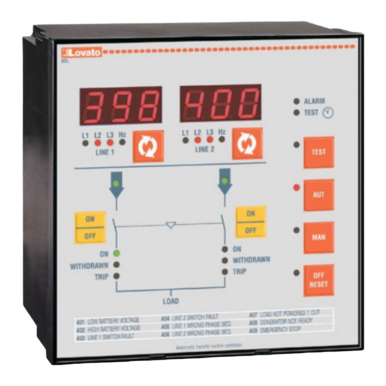
DESCRIPTION
- Microprocessor-based automatic transfer switch controller
- Two measurement inputs for three-phase + neutral voltage
- 12-24-48V
power supply
- 220-240V
power supply
- Two 3-digit 7-segment LED displays
- 22 status and measurement LED indicators
- 8-key membrane keypad
- RS232 serial interface for set-up, remote control and supervision
- RS485 opto-isolated interface (ATL30)
- Real time clock (RTC), with event logging (ATL30)
- Non-volatile memory for events and statistical data
- 8 programmable digital inputs
- 7 programmable relay outputs (5NO + 2 C/O).
AUTOMATIC TRANSFER SWITCH CONTROLLER
Instructions manual
G
B
Page
1
2
2
3
3
3
3
4
4
4
4
4
4
4
4
5
5
5
6
7
7
8
9
9
10
10
10
11
11
11
11
11
12
12
13
16
1
Publicidad
Capítulos
Tabla de contenido

Manuales relacionados para LOVATO ELECTRIC ATL20


Resumen de contenidos para LOVATO ELECTRIC ATL20
-
Página 1: Tabla De Contenido
MECHANICAL DIMENSIONS AND PANEL CUT-OUT ................................WIRING DIAGRAMS ..........................................TECHNICAL CHARACTERISTICS ......................................VERSIONS – ATL20 - base version, 144x144mm housing. – ATL30 - like base version plus real time clock and RS485 interface. DESCRIPTION – Microprocessor-based automatic transfer switch controller –... -
Página 2: Applications, Installation
NOTES ABOUT POWER SUPPLY CIRCUITS – ATL20 and ATL30 have a dual power supply circuit, that means they can operate with both AC and DC supply or with only one of the two indifferently. – In presence of both power supplies, energy is drawn from the AC source. In this case, only a little power is drawn from the DC source, needed to allow operation of the supply circuit itself. -
Página 3: Operating Mode Selection
STATUS LEDS – Some LEDs are present on the front panel; they show the status of the unit and/or circuit breakers it controls. – The following table details the meaning of the different LEDs. Some of them have two colours and have a different meaning depending on the colour. FLASHING Voltage and frequency within set limits Voltage or frequency out of limits... -
Página 4: Utility-To-Utility Application
UTILITY-TO-UTILITY APPLICATION – In the utility-to-utility (U-U) application, the load is usually connected to the main utility and the transfer to the secondary utility occurs at main line anomaly or when a transfer signal is given externally. GENERATOR-TO-GENERATOR APPLICATION – In this case, two generators are controlled, each with a start-stop relay and feedback signals, if any. –... -
Página 5: Parameters Set-Up
– Each anomaly has an independent delay time. The anomaly must last uninterruptedly more than the time specified to invalidate the voltage presence signal. – When all the line parameters are restored within the specified limits, before the line may be used, the line presence delay time must elapse. The duration of this time is specified by two independent parameters, one defining the delay time when the alternate line is available, and a second one, normally shorter, that defines the delay in case of the alternate line is not available. -
Página 6: Menu P2 - General Data
For instance, if you set time at 12:30 and rotation every 6h, there will be a changeover at 12:30, one at 18:30, one at 0:30, etc. P2.23 - Defines whether, it must signal the need to set the calendar clock or not (Set rtc message) when the ATL is powered. For ATL20, if the real-time-clock is not set after power-on, it returns to the default value. -
Página 7: Menu P3 - Line 1 Voltage Control
MENU P3 - LINE 1 VOLTAGE CONTROL Function Range Default P3.01 Minimum voltage threshold - trip 70…98% 85% Ue P3.02 Minimum voltage threshold - restore 75…100% 90% Ue P3.03 Minimum voltage threshold delay 0.1 …. 900s 1.0s P3.04 Maximum voltage threshold - trip 102…120% / OFF 115% Ue P3.05... -
Página 8: Menu P5 - Programmable Inputs
MENU P5 – PROGRAMMABLE INPUTS Function Range Default P5.1 Prg Inp Function 1 term. 4.1 See following list FB.1 P5.2 Prg Inp Function 2 term. 4.2 See following list FB.2 P5.3 Prg Inp Function 3 term. 4.3 See following list tr.1 P5.4 Prg Inp Function 4 term. -
Página 9: Menu P6 - Programmable Outputs
MENU P6 - PROGRAMMABLE OUTPUTS Function Range Default P6.1 Prg Out Function 1 term. 1.1 See following list OP.1 P6.2 Prg Out Function 2 term. 1.3 See following list CL.2 P6.3 Prg Out Function 3 term. 2.1 See following list OP.2 P6.4 Prg Out Function 4 term. -
Página 10: Menu P8 - Automatic Test
– Press keys B and D to modify the setting of the selected parameter. – Press key H to quit parameters set-up. – For ATL20, after de-energising and energising again the RTC shall be reset. This situation is signalled by the flashing wording SET RTC and by the flashing TEST LED... -
Página 11: Alarms
SCADA software that supports Modbus protocol. – ATL20 and ATL30 can be connected directly in peer-to-peer configuration using the RS232 serial interface port and cable with order code 51C2. – ATL30 can also be connected through RS485 interface in a multi-drop configuration, using the wiring diagrams given in the following pages. -
Página 12: Rear Terminal Connections
REAR TERMINAL CONNECTIONS B300 250V~ 12A AC1 B300 250V~ 8A AC1 B300 250V~ 12A AC1 B300 250V~ 8A AC1 B300 DIGITAL 250V~ INPUTS 8A AC1 B300 250V~ 8A AC1 B300 250V~ 8A AC1 MECHANICAL DIMENSIONS AND CUT-OUT 138.5 ALARM TEST L1 L2 L3 Hz L1 L2 L3 Hz LINE 1... -
Página 13: Wiring Diagrams
WIRING DIAGRAMS Control of motorised circuit breakers LINE 1 LINE 2 L1 L2 L3 N RS232 SG 6.1 B 6.2 RS485 A 6.3 TR 6.4 LINE 1 LINE 2 DIGITAL INPUTS SUPPLY DUAL POWER SUPPLY + _ _ L3 N LOAD Parameter setting for the illustrated wiring diagram. - Página 14 Control of contactors LINE 1 LINE 2 L1 L2 L3 N RS232 SG 6.1 B 6.2 RS485 A 6.3 TR 6.4 K1 * K2 * DIGITAL INPUTS SUPPLY LINE 1 LINE 2 + _ _ DUAL POWER SUPPLY L3 N LOAD Parameter setting for the illustrated wiring diagram * Utilizzati solo per alimentazione AC.
- Página 15 UPS standby power supply Generating set applications only AC auxiliary voltage controlled by ATL Line 2 coming from generator LINE 1 LINE 2 SUPPLY To circuit breakers or changeover supply FROM BATTERY Notes: – The output on terminals 3.1-3.2 (parameter P6.05) must be set with L1.S function (Line 1 status). –...
-
Página 16: Technical Characteristics
IP41 on front UL ratings 8A, B300, 1A 30V Pilot Duty IP20 terminals Weight 1040g (ATL20); 1050g (ATL30) Certifications and compliance Certifications obtained cULus, GOST UL marking For use on a Flat surface of a Type 1 Enclosure. Use 75°C copper (CU) conductor and wire size range 18...12 AWG, stranded or solid. -
Página 17: Manuale Operativo
DIMENSIONI MECCANICHE E FORATURA ....................................SCHEMI DI COLLEGAMENTO ........................................CARATTERISTICHE TECNICHE ......................................... VERSIONI – ATL20 - versione base, contenitore 144x144mm. – ATL30 - come versione base ma con l’aggiunta di orologio datario e interfaccia RS485. DESCRIZIONE – Commutatore automatico di rete a microprocessore. -
Página 18: Applicazioni E Installazione
– Programmare i parametri in funzione dello schema di collegamento adottato, facendo particolare attenzione alla programmazione degli ingressi / uscite. NOTE SUL CIRCUITO DI ALIMENTAZIONE – ATL20 e ATL30 dispongono di un doppio circuito di alimentazione, questo significa che possono funzionare con entrambe le alimentazioni AC e DC, oppure con una delle due indifferentemente. -
Página 19: Lampeggiante
LED STATO – Sul frontale sono presenti alcuni LED che indicano lo stato dell’apparecchio e/o degli interruttori da esso comandati. – Nella seguente tabella sono riportati i significati dei vari LED. Alcuni di essi sono bicolori ed assumono un differente significato a seconda del colore. ACCESO SPENTO LAMPEGGIANTE... -
Página 20: Applicazione Rete-Rete
APPLICAZIONE RETE-RETE – Nell’applicazione rete-rete (U-U, utility-utility), il carico è normalmente collegato alla rete prioritaria e il trasferimento sulla secondaria avviene in caso di anomalia sulla primaria o di segnale di trasferimento imposto dall’esterno. APPLICAZIONE GENERATORE-GENERATORE – In questo caso vengono gestiti due generatori, ciascuno con un relè di start-stop ed eventuali segnali di ritorno. –... -
Página 21: Impostazione Dei Parametri (Set-Up)
– Ciascuna delle anomalie ha un tempo di ritardo indipendente. L’anomalia deve durare consecutivamente più del tempo specificato per invalidare il segnale di presenza tensione. – Quando tutti i parametri della linea rientrano all’interno dei limiti specificati, prima che la stessa possa essere considerata utilizzabile, deve trascorrere il tempo di ritardo presenza linea. -
Página 22: Menu P2 - Dati Generali
P2.23 - Definisce se quando l’ATL viene alimentato, deve segnalare la necessità di impostare l’orologio datario (messaggio Set rtc) oppure no. Nel caso di ATL20, se non viene impostato l’orologio datario, esso ritorna al valore di default. P2.24 - Abilita o disabilita il controllo di tensione in modalità MAN. Se il controllo è abilitato, non vengono effettuati trasferimenti fra le due linee, ma il singolo dispositivo di commutazione viene aperto/chiuso quando la sua tensione esce/rientra dai limiti. -
Página 23: Menu P3 - Controllo Tensione Linea 1
MENU P3 - CONTROLLO TENSIONE LINEA 1 Funzione Range Default P3.01 Soglia tensione minima - sgancio 70…98% 85% Ue P3.02 Soglia tensione minima - ripristino 75…100% 90% Ue P3.03 Ritardo soglia tensione minima 0.1 …. 900s 1.0s P3.04 Soglia tensione massima - sgancio 102…120% / OFF 115% Ue P3.05... -
Página 24: Menu P5 - Ingressi Programmabili
MENU P5 - INGRESSI PROGRAMMABILI Funzione Range Default P5.1 Funzione ing prg 1 mors. 4.1 Vedi lista seguente FB.1 P5.2 Funzione ing prg 2 mors. 4.2 Vedi lista seguente FB.2 P5.3 Funzione ing prg 3 mors. 4.3 Vedi lista seguente tr.1 P5.4 Funzione ing prg 4 mors. -
Página 25: Menu P6 - Uscite Programmabili
MENU P6 - USCITE PROGRAMMABILI Funzione Range Default P6.1 Funzione usc. prg 1 mors. 1.1 Vedi lista seguente OP.1 P6.2 Funzione usc. prg 2 mors. 1.3 Vedi lista seguente CL.2 P6.3 Funzione usc. prg 3 mors. 2.1 Vedi lista seguente OP.2 P6.4 Funzione usc. -
Página 26: Menu P8 - Test Automatico
– Premere i tasti B e D per modificare l’impostazione del parametro selezionato. – Premere il tasto H per uscire dalla impostazione parametri. – Per ATL20, dopo aver tolto e rimesso tensione sarà necessario re-impostare l’orologio datario. Questa situazione viene segnalata dalla scritta SET RTC lampeggiante e dal lampeggio del LED TEST... -
Página 27: Allarmi
SCADA in grado di supportare il protocollo Modbus. – ATL20 e ATL30 possono essere collegati direttamente in configurazione punto-punto tramite interfaccia RS232 e relativo cavo cod. 51C2. – ATL30 può anche essere collegato tramite interfaccia RS485 in configurazione multidrop, secondo le modalità indicate nei successivi schemi di collegamento. -
Página 28: Connessioni Sul Retro
CONNESSIONI SUL RETRO B300 250V~ 12A AC1 B300 250V~ 8A AC1 B300 250V~ 12A AC1 B300 250V~ 8A AC1 B300 DIGITAL 250V~ INPUTS 8A AC1 B300 250V~ 8A AC1 B300 250V~ 8A AC1 DIMENSIONI MECCANICHE E FORATURA 138.5 ALARM TEST L1 L2 L3 Hz L1 L2 L3 Hz LINE 1... -
Página 29: Schemi Di Collegamento
SCHEMI DI COLLEGAMENTO Comando interruttori motorizzati LINE 1 LINE 2 L1 L2 L3 N RS232 SG 6.1 B 6.2 RS485 A 6.3 TR 6.4 LINE 1 LINE 2 DIGITAL INPUTS SUPPLY DUAL POWER SUPPLY + _ _ L3 N LOAD Programmazione parametri per lo schema in figura. - Página 30 Comando contattori LINE 1 LINE 2 L1 L2 L3 N RS232 SG 6.1 B 6.2 RS485 A 6.3 TR 6.4 K1 * K2 * DIGITAL INPUTS SUPPLY LINE 1 LINE 2 + _ _ DUAL POWER SUPPLY L3 N LOAD Programmazione parametri per lo schema in figura * Utilizzati solo per alimentazione AC.
- Página 31 Alimentazione di sicurezza da UPS Solo per applicazioni con gruppi elettrogeni Tensione ausiliaria AC controllata mediate ATL Linea 2 proveniente da generatore LINE 1 LINE 2 SUPPLY To circuit breakers or changeover supply FROM BATTERY Note: – L'uscita sui morsetti 3.1-3.2 (parametro P6.05) va programmata con la funzione L1.S (Line 1 status) –...
-
Página 32: Caratteristiche Tecniche
8A, B300, 1A 30V servizio ausiliario Grado di protezione IP41 sul fronte IP20 sui morsetti Peso 1040g (ATL20); 1050g (ATL30) Omologazioni e conformità Omologazioni ottenute cULus, GOST UL marking For use on a Flat surface of a Type 1 Enclosure. -
Página 33: Versiones, Descripción
DIAGRAMAS DE CONEXIÓN ........................................CARACTERÍSTICAS TÉCNICAS ......................................... VERSIONES – ATL20 - Versión base, caja de 144x144mm. – ATL30 - como versión base con la adición de Reloj calendario e interfaz serie RS485. DESCRIPCIÓN – Conmutador automático de redes con microprocesador. -
Página 34: Aplicaciones Y Instalación
– Programar los parámetros en función del esquema de conexión seleccionado, prestando particular atención a las entradas y las salidas. NOTAS ACERCA DEL CIRCUITO DE ALIMENTACIÓN AUXILIAR – ATL20 Y ATL30 disponen de un doble circuito de alimentación auxiliar, esto significa que pueden funcionar con ambas alimentaciones AC y DC, o con una de las dos indiferentemente. -
Página 35: Selección De Modo De Operación
LEDS DE ESTADOS – Algunos LEDs en el panel frontal indican el estado del aparato y/o de los interruptores que controla. – En la siguiente tabla se explica el significado de los diversos LEDs, algunos de los cuales son bicolor y asumen un significado diferente con el segundo color. INTERMITENTE Tensión y frecuencia dentro de los Tensión o frecuencia fuera de los... -
Página 36: Aplicación Red-Red
APLICACIÓN RED-RED – En la aplicación Red-Red (U-U), la carga está conectada normalmente a la línea prioritaria y la conmutación a la secundaria se produce en caso de anomalía en la línea prioritaria o de una señal de mando externo. APLICACIÓN GENERADOR-GENERADOR –... -
Página 37: Ajuste De Parámetros (Set-Up)
– Cada una de las anomalías tiene un tiempo de retardo independiente. La anomalía debe permanecer por lo tanto un tiempo mayor que el ajustado para invalidar la señal de presencia de tensión. – Cuando todos los parámetros de la línea están dentro de los límites especificados, antes que la misma pueda considerarse utilizable debe transcurrir el tiempo de retardo de presencia de línea. -
Página 38: Menú P2 -Datos Generales
P2.23 - Define si el ATL, al recibir energía, debe señalar la necesidad de ajustar el reloj calendario (Mensaje Set rtc.) o no. En el caso del ATL20 si no se ajusta el reloj calendario, este retorna a su valor de defecto. -
Página 39: Menú P3 - Control De Tensión Línea 1
MENÚ P3 -CONTROL DE TENSIÓN LÍNEA 1 Función Rango Default P3.01 Umbral de mínima tensión - disparo 70…98% 85% Ue P3.02 Umbral de mínima tensión - restauración 75…100% 90% Ue P3.03 Retardo de umbral de mínima tensión 0.1 …. 900s 1.0s P3.04 Umbral de máxima tensión -disparo... -
Página 40: Menú P5 - Entradas Programables
MENÚ P5 - ENTRADAS PROGRAMABLES Función Rango Default P5.1 Función ent. Prog. 1 term. 4.1 Ver lista siguiente FB.1 P5.2 Función ent. Prog. 2 term. 4.2 Ver lista siguiente FB.2 P5.3 Función ent. Prog. 3 term. 4.3 Ver lista siguiente tr.1 P5.4 Función ent. -
Página 41: Menú P6 - Salidas Programables
MENÚ P6 - SALIDAS PROGRAMABLES Función Rango Default P6.1 Función prog. sal. 1 term. 1.1 Ver lista siguiente OP.1 P6.2 Función prog. sal. 2 term. 1.3 Ver lista siguiente CL.2 P6.3 Función prog. sal. 3 term. 2.1 Ver lista siguiente OP.2 P6.4 Función prog. -
Página 42: Menú P8 - Prueba Automática (Test)
– Presionar la tecla H para salir de la configuración de parámetros. – Para el tipo ATL20, después de la puesta en tensión será necesario volver a configurar el reloj calendario. Esta situación es señalizada por el mensaje SET RTC intermitente y del LED intermitente TEST LED Función... -
Página 43: Alarmas
ATLSW o utilizando un software genérico SCADA que soporte el protocolo Modbus. – Los modelos ATL20 y ATL30 pueden conectarse directamente en configuración punto a punto a través del puerto RS232 con el cable código 51C2. – El modelo ATL30 puede también conectarse a través del puerto RS485 en configuración multipunto, utilizando los diagramas de conexión correspondientes (diagramas de conexión que aparecen en las siguientes páginas). -
Página 44: Terminales De Conexión
TERMINALES DE CONEXION TRASEROS B300 250V~ 12A AC1 B300 250V~ 8A AC1 B300 250V~ 12A AC1 B300 250V~ 8A AC1 B300 DIGITAL 250V~ INPUTS 8A AC1 B300 250V~ 8A AC1 B300 250V~ 8A AC1 DIMENSIONES MECANICAS Y TROQUEL DE INSTALACION 138.5 ALARM TEST... -
Página 45: Diagramas De Conexión
DIAGRAMAS DE CONEXION Mando de interruptores motorizados LINE 1 LINE 2 L1 L2 L3 N RS232 SG 6.1 B 6.2 RS485 A 6.3 TR 6.4 LINE 1 LINE 2 DIGITAL INPUTS SUPPLY DUAL POWER SUPPLY + _ _ L3 N LOAD Programación de parámetros para el esquema de la figura. -
Página 46: Circuitos De Alimentación
Mando contactores LINE 1 LINE 2 L1 L2 L3 N RS232 SG 6.1 B 6.2 RS485 A 6.3 TR 6.4 K1 * K2 * DIGITAL INPUTS SUPPLY LINE 1 LINE 2 + _ _ DUAL POWER SUPPLY L3 N LOAD Programación de parámetros para el esquema de la figura * Utilizzati solo per alimentazione AC. - Página 47 Alimentación de reserva con UPS Únicamente para aplicaciones con grupos electrógenos Tensión auxiliar AC controlada por ATL Línea 2 proveniente del generador LINE 1 LINE 2 SUPPLY To circuit breakers or changeover supply FROM BATTERY Notas: – La salida en los terminales 3.1-3.2 (parámetro P6.05) debe estar programada con la función L1.S (Line 1 status) –...
-
Página 48: Características Técnicas
IP41 en el frente Datos de empleo UL 8A, B300, 1A 30V servicio auxiliar IP20 en los bornes Peso 1040g (ATL20); 1050g (ATL30) Homologaciones y conformidad Homologaciones obtenidas cULus, GOST UL marking For use on a Flat surface of a Type 1 Enclosure.