Tabla de contenido
Publicidad
Idiomas disponibles
Idiomas disponibles
Enlaces rápidos
Fusores de adhesivo
ProBluer
Modelo P4, P7 y P10
Manual P/N 213570_05
- Spanish -
Edición 9/11
This document contains important safety information
Be sure to read and follow all safety information in this
document and any other related documentation.
NORDSON CORPORATION • DULUTH, GEORGIA • USA
www.nordson.com
Publicidad
Tabla de contenido
Solución de problemas

Manuales relacionados para Nordson ProBlue P4


Resumen de contenidos para Nordson ProBlue P4
- Página 1 Modelo P4, P7 y P10 Manual P/N 213570_05 - Spanish - Edición 9/11 This document contains important safety information Be sure to read and follow all safety information in this document and any other related documentation. NORDSON CORPORATION • DULUTH, GEORGIA • USA www.nordson.com...
- Página 2 Cobalt, ContourCoat, Controlled Fiberization, Control Weave, CPX, cSelect, Cyclo‐Kinetic, DispensLink, DropCure, Dry Cure, DuraBraid, DuraCoat, e.dot+, E‐Nordson, Easy Clean, EasyOn, EasyPW, Eclipse, Equalizer, Equi=Bead, Exchange Plus, FillEasy, Fill Sentry, Flow Coat, Fluxplus, G‐Net, G‐Site, Get Green With Blue, Gluie, Ink‐Dot, IntelliJet, iON, Iso‐Flex, iTrend, KVLP, Lacquer Cure, Maxima, Mesa, MicroFin, MicroMax, Mikros, MiniBlue, MiniEdge,...
-
Página 3: Tabla De Contenido
........2‐8 P/N 213570_05 E 2011 Nordson Corporation... - Página 4 ..........3‐47 Ajuste de las comunicaciones del fusor ......3‐47 E 2011 Nordson Corporation P/N 213570_05...
- Página 5 DP.5 Check the Resistance of the Tank and Manifold Heaters 6‐17 ProBlue Troubleshooting Flowcharts ......6‐21 P/N 213570_05 E 2011 Nordson Corporation...
- Página 6 ........7‐40 E 2011 Nordson Corporation P/N 213570_05...
- Página 7 ......C‐5 Using Nordson Configuration Manager ......
- Página 8 ........D‐34 E 2011 Nordson Corporation P/N 213570_05...
- Página 9 ..........E‐23 P/N 213570_05 E 2011 Nordson Corporation...
- Página 10 VIII Tabla de materias E 2011 Nordson Corporation P/N 213570_05...
-
Página 11: Nordson International
46‐40‐932 882 Switzerland 41‐61‐411 3838 41‐61‐411 3818 United King Hot Melt 44‐1844‐26 4500 44‐1844‐21 5358 Industrial 44‐161‐498 1500 44‐161‐498 1501 Coating Systems Distributors in Eastern & Southern Europe DED, Germany 49‐211‐92050 49‐211‐254 658 E 2011 Nordson Corporation NI_EN_O‐0211 All rights reserved... -
Página 12: Outside Europe / Hors D'europe / Fuera De Europa
O‐2 Introduction Outside Europe / Hors d'Europe / Fuera de Europa For your nearest Nordson office outside Europe, contact the Nordson offices below for detailed information. Pour toutes informations sur représentations de Nordson dans votre pays, veuillez contacter l'un de bureaux ci‐dessous. -
Página 13: Seguridad
¡PRECAUCIÓN! (Utilizado sin la señal de alerta de seguridad) Indica una situación potencialmente peligrosa que, si no se evita, puede provocar daños en el equipo o en la instalación. Edición 10-11 E 2011 Nordson Corporation... -
Página 14: Responsabilidades Del Propietario Del Equipo
Realizar inspecciones de seguridad para asegurarse de que se cumplan las prácticas requeridas. Volver a evaluar las prácticas y los procedimientos de seguridad siempre que se realice algún cambio en el proceso o equipo. Edición 10-11 E 2011 Nordson Corporation... -
Página 15: Cualificaciones Del Usuario
No modificar el equipo. No utilizar materiales incompatibles ni dispositivos auxiliares no aprobados. Ponerse en contacto con el representante de Nordson en caso de cualquier duda o pregunta sobre los materiales compatibles o el uso de dispositivos auxiliares no aprobados. -
Página 16: Instrucciones Y Mensajes De Seguridad
Ver la Hoja de datos de seguridad del material (HDSM) correspondiente. Si la configuración de instalación requerida no coincide con las instrucciones de instalación, contactar con el representante de Nordson para recibir asistencia. Colocar el equipo para garantizar una operación segura. Tener en cuenta las separaciones requeridas entre el equipo y otros objetos. -
Página 17: Procedimientos De Mantenimiento Y Reparación
NOTA: Las HDSM de los compuestos de limpieza comercializados por Nordson pueden obtenerse en www.nordson.com o llamando a su representante de Nordson. Antes de volver a poner en marcha el equipo, confirmar que todos los dispositivos de seguridad funcionen correctamente. -
Página 18: Parada Del Equipo
2. Desconectar la conexión eléctrica de señal de entrada de la(s) electroválvula(s) del aplicador. 3. Reducir la presión de aire a la(s) electroválvula(s) del aplicador a cero; después eliminar la presión del aire residual entre el regulador y el aplicador. Edición 10-11 E 2011 Nordson Corporation... -
Página 19: Avisos De Seguridad Generales Y Precauciones
¡AVISO! ¡Vapores peligrosos! Antes de procesar cualquier material de adhesivo reactivo al poliuretano (PUR) o material con base disolvente en un fusor de Nordson compatible, leer y cumplir con la HDSM del material. Asegurarse de que no se superen la temperatura de procesamiento y los puntos de inflamación del material así... - Página 20 ¡AVISO! ¡Peligro de incendio o explosión! El equipo de adhesivo de Nordson no está indicado para uso en ambientes explosivos y no ha sido certificado de conformidad con la Directiva ATEX ni como no peligroso por inflamable. Además, este equipo no debe utilizarse con HM, CA, PC adhesivos con base disolvente que pueden crear una atmósfera...
- Página 21 ¡PRECAUCIÓN! El equipo de termofusible de Nordson está probado en fábrica con disolvente de tipo R de Nordson que contiene plastificante de adipato de poliéster. Ciertos materiales termofusibles pueden reaccionar con disolvente de tipo R y formar una goma sólida que obstruye el equipo.
-
Página 22: Otras Precauciones De Seguridad
3. NO intentar retirar el termofusible solidificado de la piel. 4. En caso de quemaduras graves, tratar las descargas. 5. Buscar de inmediato atención médica especializada. Entregar la HDSM del adhesivo termofusible al personal médico que le atienda. Edición 10-11 E 2011 Nordson Corporation... -
Página 23: Etiquetas Y Rótulos De Seguridad
AVISO Peligro de quemaduras. Adhesivo caliente. Eliminar la presión antes de intervenir. AVISO Tensión peligrosa. Desconectar todas las conexiones de la fuente de la alimentación antes intervenir. Significado del símbolo: ¡Superficie caliente! No tocar. Edición 10-11 E 2011 Nordson Corporation... - Página 24 1‐12 Seguridad Edición 10-11 E 2011 Nordson Corporation...
-
Página 25: Introducción
ProBluet 4 (P4), ProBlue 7 (P7) y ProBlue 10 (P10). En caso necesario, se remite al lector para que vea la documentación proporcionada con otros productos Nordson o productos proporcionados por terceros. A diferencia de la capacidad del tanque, la capacidad de la manguera/pistola y el aspecto externo, todos los fusores ProBlue son idénticos en cuanto a... -
Página 26: Otras Fuentes De Información
Asistencia online Visitar www.enordson/support para descargar actualizaciones de firmware del fusor y software. Visitar www.emanuals.nordson.com para descargar manuales de producto y hojas de instrucciones. CD de recursos del producto El CD de recursos, guardado en la parte posterior de este manual, contiene una versión electrónica de este manual, información sobre las piezas y otros... -
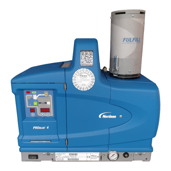
Página 27: Descripción Del Producto
2‐3 Introducción Descripción del producto Ver la figura 2‐1. Los fusores de adhesivo ProBlue de Nordson se utilizan junto con las mangueras y pistolas de termofusible de Nordson para crear un sistema de aplicación de termofusible. El fusor convierte en líquido el adhesivo termofusible en forma sólida y mantiene el mismo a la temperatura deseada. -
Página 28: Uso Previsto
230_C (450_F). Ser utilizados con mangueras y pistolas de termofusible compatibles fabricadas por Nordson Corporation. Ser utilizados en ambientes no explosivos. Restricciones de uso Utilizar los fusores ProBlue sólo para los fines para los que fueron diseñados. -
Página 29: Identificación Del Fusor
El modelo y el número de pieza están indicados en la placa de identificación del equipo localizada en la parte delantera del fusor. 1/3O AC 200-240 V 60HZ 35A 1/3ON/PEAC 400/230 V 50HZ 33A Fig. 2‐2 Placa de identificación del equipo P/N 213570_05 E 2011 Nordson Corporation... -
Página 30: Componentes Clave
12. Puerta del armario eléctrico 3. Módulos de manguera/pistola 8. Manómetro 13. Panel de control (ver figura 2‐4) 4. Chasis 9. Puerta de la carcasa de la bomba 5. Distribuidor 10. Interruptor de control E 2011 Nordson Corporation P/N 213570_05... - Página 31 7. Teclado 3. Teclas/LED de componente 8. Pantalla izquierda y tecla de desplazamiento 4. Pantalla derecha y teclas de desplazamiento 9. LED de servicio 5. Teclas de función 10. LED de nivel bajo de tanque P/N 213570_05 E 2011 Nordson Corporation...
-
Página 32: Equipamiento Opcional
Seleccionar el producto FillEasy o FillMaster Base de ampliación de 8 mangueras/pistolas que aumenta la capacidad de un fusor de adhesivo P10 de 6 mangueras/pistolas a 8 mangueras/pistolas. E 2011 Nordson Corporation P/N 213570_05... -
Página 33: Instalación
Ver apéndice E para más información acerca de la instalación de fusores de adhesivo ProBlue de 400/480 voltios. Después de haber concluido los procedimientos descritos en el apéndice E, se le remitirá de nuevo a esta sección para configurar el fusor. P/N 213570_05 E 2011 Nordson Corporation... -
Página 34: Resumen
En caso necesario, algunas entradas de tabla contienen también información con referencias cruzadas. Las tablas de información adicional se indican con el símbolo que se muestra a la izquierda. E 2011 Nordson Corporation P/N 213570_05... -
Página 35: Tareas De Instalación
Procesos de aplicación de adhesivo termofusible Cableado de energía industrial y de control Prácticas de instalación mecánica industriales Control de proceso básico e instrumentación P/N 213570_05 E 2011 Nordson Corporation... -
Página 36: Requerimientos De Instalación
Tab. 3‐1 Distancias de instalación Ítem Descripción Distancia requerida La distancia desde el borde exterior de una manguera Nordson de P4 = 370 mm (14,5 pulgadas) pulgadas a la cara frontal del fusor cuando hay que conectar al P7 = 370 mm (14,5 pulgadas) fusor un racor de manguera de 90 grados. -
Página 37: Ventilación
No instalar o emplear de forma incorrecta el interruptor de desconexión en el momento de realizar el mantenimiento del fusor, ya de lo contrario pueden producirse daños personales o incluso la muerte. P/N 213570_05 E 2011 Nordson Corporation... -
Página 38: Aire Comprimido
0,7 bar (10 psi) puede hacer que el funcionamiento de la bomba se vuelva inestable. Nordson recomienda instalar una válvula de aislamiento en la línea de suministro de aire de planta justo delante de la instalación del fusor. - Página 39 3‐7 Instalación Esta página está en blanco intencionadamente. P/N 213570_05 E 2011 Nordson Corporation...
-
Página 40: Desembalaje Del Fusor
Antes de iniciar la instalación, extraer el fusor del palet, localizar el kit de instalación e inspeccionar el fusor por si tuviera piezas dañadas o por si faltara alguna pieza. Informar al representante Nordson acerca de cualquier problema. Contenido del kit de instalación El kit de instalación suministrado con el fusor contiene los componentes... - Página 41 3. Conector de entrada y salida (2) 8. Racor de manguera de 45 grados 4. Abrazadera de cable 9. Racor de manguera de 90 grados 5. Conector eléctrico 10. Protección de distribuidor de 6 mangueras (sólo P10) P/N 213570_05 E 2011 Nordson Corporation...
-
Página 42: Montaje Del Fusor
OBSERVACION: La base inferior de montaje tiene el mismo encolado de montaje de perno que los fusores Nordson de 3100V y 3400V. 3. Enclavijar la base inferior a la máquina principal utilizando para ello cuatro pernos roscados de 8 mm ( pulgadas) con material de sujeción. - Página 43 8. Fijar el fusor en la base inferior girando cada uno de los tornillos de bloqueo localizados en el frente del fusor en el sentido de las agujas del reloj hasta que hagan tope. P/N 213570_05 E 2011 Nordson Corporation...
- Página 44 3‐12 Instalación Montaje del fusor (cont.) Fig. 3‐4 Montaje de la base inferior y del fusor E 2011 Nordson Corporation P/N 213570_05...
-
Página 45: Configuración Del Servicio Eléctrico
3‐2 asumen que cada módulo manguera/pistola se utiliza con su máxima capacidad de 2000 vatios. OBSERVACION: Contactar con el representante Nordson para asistencia a la hora de calcular la potencia de salida del fusor para tensiones de trabajo distintas de 230 voltios o para asistencia a la hora de calcular la salida de potencia exacta para mangueras y pistolas específicas fabricadas por Nordson Corporation. - Página 46 La toma de tierra está marcada con PE/G. 7. Conectar el puente a tierra que está conectado a la toma de tierra, al pilar de tierra que está localizado en la base inferior. E 2011 Nordson Corporation P/N 213570_05...
- Página 47 3‐15 Instalación EJEMPLO SÓLO PE / G (Se muestra el cableado 3/N/PE AC) Fig. 3‐5 Conectar el cable de alimentación, el conductor a tierra y el puente a tierra P/N 213570_05 E 2011 Nordson Corporation...
- Página 48 Si el servicio eléctrico ha sido configurado correctamente, en el panel de control del fusor aparecerán guiones. E 2011 Nordson Corporation P/N 213570_05...
- Página 49 3‐17 Instalación Fig. 3‐6 Conexión de un conector de tensión P/N 213570_05 E 2011 Nordson Corporation...
-
Página 50: Conexión De Un Suministro De Aire Comprimido
OBSERVACION: La presión de aire mínima es de 0,7 bar (10 psi). Manejar el fusor con presión de aire inferior a 0,7 bar (10 psi) puede hacer que el funcionamiento de la bomba se vuelva inestable. E 2011 Nordson Corporation P/N 213570_05... - Página 51 3‐19 Instalación P/N 1034145 NPTF BSPP Fig. 3‐7 Conectar el filtro de aire y la línea de suministro de aire de planta P/N 213570_05 E 2011 Nordson Corporation...
-
Página 52: Conexión De Mangueras Y Pistolas
Observar las siguientes directrices: Para obtener información acerca de la elección de manguera de termofusible correcta de Nordson para su proceso de fabricación, ver la última edición del equipo de aplicación de adhesivo termofusible Catálogo de piezas de repuesto o ponerse en contacto con el representante Nordson. - Página 53 Utilizar los racores de manguera de 45 ó 90 grados suministrados en el mangueras P10 kit de instalación. OBSERVACION: Sólo los racores de 90 grados se envían con los fusores P4 y P7. Fig. 3‐8 Conexión de una manguera P/N 213570_05 E 2011 Nordson Corporation...
- Página 54 P10 Para obtener información acerca de la elección de pistola de termofusible Nordson más apropiada para su proceso de fabricación, ver la última edición de equipo de aplicación de adhesivo termofusible Catálogo de piezas de repuesto o ponerse en contacto con el representante Nordson.
- Página 55 3‐23 Instalación Esta página está en blanco intencionadamente. P/N 213570_05 E 2011 Nordson Corporation...
-
Página 56: Configuración Del Fusor
Temperatura de punto de referencia del tanque, mangueras y pistolas, más adelante en este manual, para completar el proceso de instalación. Si resulta necesario realizar cambios en la configuración de fábrica o si quieren conocerse otros parámetros de funcionamiento, ir a Parámetros de funcionamiento. E 2011 Nordson Corporation P/N 213570_05... - Página 57 Grupo de parámetros que controla el reloj del fusor. El Reloj programador reloj se utiliza para encender y apagar 50 a 77 Desactivado semanal automáticamente los calefactores y para poner el fusor en modo de reposo. P/N 213570_05 E 2011 Nordson Corporation...
-
Página 58: Parámetros De Funcionamiento
Lectura o edición de parámetros de funcionamiento Sin tener en cuenta si el valor de parámetro es editable o no, el procedimiento para acceder a cada parámetro con el fin de leer o editar su valor actual es el mismo. E 2011 Nordson Corporation P/N 213570_05... - Página 59 (‐‐‐‐) durante tres segundos y después volverá al valor original. 8. Repetir los pasos 5 a 7 para leer o cambiar el siguiente número de parámetro secuencial o pulsar la tecla Ajuste para salir del modo de ajuste. P/N 213570_05 E 2011 Nordson Corporation...
-
Página 60: Valor Predeterminado
Entrada opcional 6 0–9, 15-16 0 (desactivado) Entrada opcional 7 0–9, 15-16 0 (desactivado) Entrada opcional 8 0–9, 15-16 0 (desactivado) Entrada opcional 9 0–9, 15-16 0 (desactivado) Entrada opcional 10 0–9, 15-16 0 (desactivado) Continúa... E 2011 Nordson Corporation P/N 213570_05... -
Página 61: Rango De Valores
Programa 3 salir del reposo 0000 a 2359 —:— Programa para los lunes Programa para los martes Programa para los miércoles Programa para los jueves Programa para los viernes Programa para los sábados Programa para los domingos P/N 213570_05 E 2011 Nordson Corporation... - Página 62 Si la protección por contraseña está activada, Apéndice B, Parámetro 10 el fusor volverá al modo de protección por contraseña siempre que se salga del modo de ajuste. E 2011 Nordson Corporation P/N 213570_05...
- Página 63 3‐31 Instalación Esta página está en blanco intencionadamente. P/N 213570_05 E 2011 Nordson Corporation...
-
Página 64: Temperatura De Punto De Referencia Del Tanque, Mangueras Y Pistolas
4, Ajuste de temperaturas de componente. De la misma forma que con los parámetros de funcionamiento, podrá también guardar y restablecer las temperaturas de punto de referencia y revisar cambios pasados que se han hecho a las mismas. E 2011 Nordson Corporation P/N 213570_05... - Página 65 Cuando todos los componentes alcanzan la temperatura de punto de referencia global, el LED de listo se enciende (verde). LED de listo P/N 213570_05 E 2011 Nordson Corporation...
-
Página 66: Guardar Y Restablecer Ajustes Del Fusor
Pueden transferirse los ajustes del Ver el apéndice C, Comunicaciones del fusor fusor de un fusor a otro empleando el servicio de software de Gestión de Configuraciones de Nordson. E 2011 Nordson Corporation P/N 213570_05... - Página 67 3‐35 Instalación Esta página está en blanco intencionadamente. P/N 213570_05 E 2011 Nordson Corporation...
-
Página 68: Revisión De Cambios En Parámetro Y Temperatura De Punto De Referencia
Cada vez que se presiona la tecla de desplazamiento aparece una entrada de registro anterior. 4. Pulsar la tecla Ajuste para volver al modo de exploración automática. Desplazamiento por el registro E 2011 Nordson Corporation P/N 213570_05... - Página 69 Parámetro 4 (retardo de listo) ha sido cambiado. Ejemplo 2: Si el LED de tecla Pistola está encendido, entonces esta pantalla indicará que se ha utilizado el método global‐por‐componente para cambiar la temperatura de las pistolas. P/N 213570_05 E 2011 Nordson Corporation...
- Página 70 ”P‐_”. Para visualizar cuántas horas del calefactor han transcurrido desde un cambio específico (visualizado), presionar simultáneamente ambas teclas de desplazamiento en la pantalla derecha. E 2011 Nordson Corporation P/N 213570_05...
- Página 71 3‐39 Instalación Esta página está en blanco intencionadamente. P/N 213570_05 E 2011 Nordson Corporation...
-
Página 72: Instalación De Entradas De Fusor
NEC clase 1 y circuitos de señalización. Para reducir la Apertura de la puerta del armario posibilidad de un cortocircuito, encaminar el cable de tal forma que no eléctrico esté en contacto con ninguna placa de circuito. E 2011 Nordson Corporation P/N 213570_05... - Página 73 En caso de que el número de entrada cuatro esté siendo utilizado, conectar el conector P/N 277908 en la parte superior del receptáculo en el terminal TB2. 9 10 11 12 13 14 Fig. 3‐9 Entradas de conexión eléctrica P/N 213570_05 E 2011 Nordson Corporation...
-
Página 74: Sección 7, Piezas De Repuesto
La capacidad de entrada del fusor puede Sección 7, Piezas de repuesto aumentarse de cuatro entradas a un total de diez, añadiendo una tarjeta I/O opcional disponible en Nordson Corporation. E 2011 Nordson Corporation P/N 213570_05... - Página 75 Ver la hoja de instrucciones suministrada con la tarjeta de ampliación I/O opcional para obtener información de cableado. Cuando se instala la opción de ampliación a 8 mangueras/pistolas, la opción de Activar/Desactivar manguera/pistola 7 u 8 aparece como las opciones 15 y 16 respectivamente. P/N 213570_05 E 2011 Nordson Corporation...
-
Página 76: Instalación De Salidas Del Fusor
P/N 277909, cuyos números de terminales son del 8 al 14. 3. Conectar el conector P/N 277908 a la parte superior del receptáculo del Conector P/N 277908 terminal TB2, el cual está localizado en la placa principal. E 2011 Nordson Corporation P/N 213570_05... - Página 77 La capacidad de salida del fusor puede Sección 7, Piezas de repuesto aumentarse de tres a un total de siete salidas, añadiendo una tarjeta de ampliación I/O opcional disponible en Nordson Corporation. P/N 213570_05 E 2011 Nordson Corporation...
- Página 78 3 y 6, se generará una señal de salida de fallo y otra de salida de alerta cuando se encienda el LED de fallo. Ver la hoja de instrucciones suministrada con la tarjeta de ampliación I/O opcional para obtener información de cableado. E 2011 Nordson Corporation P/N 213570_05...
-
Página 79: Instalación De Equipamiento Opcional
Ver el apéndice C, Comunicaciones del fusor, para la información sobre la carga, la instalación y la utilización del software requerido para conectar un ordenador personal al fusor. P/N 213570_05 E 2011 Nordson Corporation... - Página 80 3‐48 Instalación E 2011 Nordson Corporation P/N 213570_05...
-
Página 81: Manejo
En caso necesario, algunas entradas de tabla contienen también información con referencias cruzadas. Las tablas de información adicional se indican con el símbolo que se muestra a la izquierda. P/N 213570_05 E 2011 Nordson Corporation... -
Página 82: Más Acerca De Los Componentes Calefactados
Los fusores de adhesivo ProBlue pueden tener dos, cuatro o seis receptáculos de manguera/pistola. Se puede pedir una base de ampliación opcional que añade dos receptáculos para dos mangueras/pistolas adicionales. E 2011 Nordson Corporation P/N 213570_05... -
Página 83: Llenado Del Tanque
3. Cerrar la tapa del tanque cuando haya terminado de llenar el tanque. Fig. 4‐1 Línea de llenado del tanque Tab. 4‐1 Capacidad del tanque Modelo Capacidad Litros Kilos Libras *Supone un adhesivo termofusible con una gravedad específica de 1 P/N 213570_05 E 2011 Nordson Corporation... -
Página 84: Puesta En Marcha Del Fusor
OBSERVACION: La presión de aire mínima es de 0,7 bar (10 psi). Manejar el fusor con presión de aire inferior a 0,7 bar (10 psi) puede hacer que el funcionamiento de la bomba se vuelva inestable. LED de listo Manómetro de aire E 2011 Nordson Corporation P/N 213570_05... - Página 85 Si el reloj programador semanal estuviese activado antes del fallo de suministro eléctrico, el fusor se reiniciará en el modo que aparece en el programa del reloj en el momento en el que se reinicie el fusor. P/N 213570_05 E 2011 Nordson Corporation...
-
Página 86: Control Del Fusor
También puede emplearse un ordenador personal para controlar el fusor. Ver el apéndice C, Comunicaciones del fusor, para la información sobre la conexión del ordenador personal al fusor y sobre la instalación del software requerido. E 2011 Nordson Corporation P/N 213570_05... -
Página 87: Confirmar Que El Fusor Está Funcionando Correctamente
Si el temporizador ha puesto el fusor en modo de reposo, puede pulsarse la tecla de reposo para volver a poner los componentes calefactados a su temperatura de punto de referencia asignada. P/N 213570_05 E 2011 Nordson Corporation... -
Página 88: Control De Temperaturas De Componente
La pantalla derecha indica la temperatura actual del componente seleccionado. 3. Pulsar dos veces la tecla Ajuste para volver al modo de exploración Pantalla de temperatura de automática. componente E 2011 Nordson Corporation P/N 213570_05... - Página 89 UP (arriba) de la pantalla derecha. Manteniendo la tecla de desplazamiento presionada mientras el fusor se encuentra en el modo de exploración automática se revela el punto de referencia de cada componente que se explora. P/N 213570_05 E 2011 Nordson Corporation...
-
Página 90: Control De Fallos Del Fusor
4. Pulsar la tecla Ajuste para volver al modo de exploración automática. Desplazamiento por el registro de fallos E 2011 Nordson Corporation P/N 213570_05... - Página 91 Cuando un fallo F1 es el resultado de la desconexión del fusor de un par de manguera/pistola, se crean dos entradas de registro de fallos. La primera entrada es para la pistola y la segunda para la manguera. P/N 213570_05 E 2011 Nordson Corporation...
- Página 92 Salida de alerta (si se Fallo de tarjeta de bus de campo. selecciona la opción de Fallos de F4/E comunicación en el salida 6) bus de campo El fusor continúa funcio‐ nando con normalidad. E 2011 Nordson Corporation P/N 213570_05...
- Página 93 2. Volver a poner el fusor en el modo de exploración automática pulsando dos veces la tecla Ajuste. 3. Pulsar la tecla Clear/Reset. Tecla Clear/Reset 4. Pulsar la tecla de Calefactor para encender los calefactores. Tecla Calefactor P/N 213570_05 E 2011 Nordson Corporation...
-
Página 94: Cómo Se Manejan Los Fallos F1, F2 Y F3
LED de listo se apaga, el LED de fallo rojo se LED de fallo (rojo) ilumina y el fusor registra el fallo en el registro de fallos. Ver Para revisar el registro de fallos más adelante en este apartado. E 2011 Nordson Corporation P/N 213570_05... -
Página 95: Cómo Se Manejan Los Fallos F4
Ver la sección 6, Localización de averías, para obtener información acerca del diagnóstico de fallos F4. 5. El fusor registra el fallo en el registro de fallos. Ver Para revisar el registro de fallos más adelante en este apartado. P/N 213570_05 E 2011 Nordson Corporation... - Página 96 235 _C (458 _F), ocurrirá inmediatamente un fallo F3 (sin periodo de control de dos minutos). Si aparece F4 en la pantalla derecha al pulsar la tecla del reloj, la función del reloj interna ha fallado. E 2011 Nordson Corporation P/N 213570_05...
-
Página 97: Control Del Nivel De Adhesivo Termofusible En El Tanque
LED de nivel bajo localizado dentro de la tecla de tanque. Nordson recomienda mantener el tanque al menos medio llenado mientras el fusor está funcionando. OBSERVACION: El fusor está por tanto equipado con una salida de bajo LED de nivel bajo (amarillo) nivel que puede conectarse a un dispositivo de señalización suministrado... -
Página 98: Control Del Intervalo De Servicio
Clear/Reset para apagar el LED de servicio y restablecer el tiempo de LED de servicio (amarillo) intervalo de servicio. Tecla Clear/Reset El ajuste predeterminado para el Apéndice B, Parámetro 5 tiempo de intervalo de servicio es de 500 horas. E 2011 Nordson Corporation P/N 213570_05... -
Página 99: Ajuste De Temperaturas De Componente
Todos los componentes empiezan a calentarse o enfriarse a la nueva Tecla Enter temperatura de punto de referencia global. Cuando todos los componentes alcanzan su temperatura de punto de referencia, el LED de listo se enciende (verde). LED de listo P/N 213570_05 E 2011 Nordson Corporation... - Página 100 Introducir la contraseña del fusor, más adelante en esta sección. 5. Pulsar la tecla Enter. Las mangueras o pistolas comienzan a calentarse o enfriarse a su nueva temperatura de punto de referencia. E 2011 Nordson Corporation P/N 213570_05...
- Página 101 6. 6. Pulsar cualquier tecla de componente (tanque, manguera o pistola). El componente seleccionado empieza a calentarse o enfriarse a la nueva temperatura de punto de referencia. P/N 213570_05 E 2011 Nordson Corporation...
- Página 102 40 _C y 230 _C. Cuando las unidades de temperatura se establecen en grados Fahrenheit, las temperaturas de punto de referencia mínimas y máximas son de 100 _F y 450 _F. E 2011 Nordson Corporation P/N 213570_05...
- Página 103 Pueden guardarse los cambios de las Sección 3, Instalación, Guardar y restablecer ajustes temperaturas de punto de del fusor referencia pulsando simultáneamente la tecla 1 y la tecla Ajuste. P/N 213570_05 E 2011 Nordson Corporation...
-
Página 104: Introducir La Contraseña Del Fusor
Ajuste. La contraseña de fusor se crea y Sección 3, Configuración del fusor activa/desactiva durante el ajuste del sistema. E 2011 Nordson Corporation P/N 213570_05... -
Página 105: Utilización De Las Teclas De Función Del Fusor
Cuando se produce un fallo (ver Control de fallos del fusor, anteriormente en esta sección) los calefactores se apagan automáticamente. La tecla de calefactor se utiliza para volver a encender los calefactores después de Tecla Calefactor corregir una condición de fallo. P/N 213570_05 E 2011 Nordson Corporation... -
Página 106: Tecla Bomba
Cuando se pone el fusor en modo de ajuste, la exploración automática se para y las pantallas izquierda y derecha se utilizan para seleccionar y leer o editar los parámetros de funcionamiento. Tecla Ajuste E 2011 Nordson Corporation P/N 213570_05... -
Página 107: Tecla De Reloj Programador Semanal
El reloj funcionará incluso si el fusor tiene fallos o está en modo de ajuste. Si aparece F4 en la pantalla derecha al Sección 7, Localización de averías pulsar la tecla del reloj, la función del reloj interna ha fallado. P/N 213570_05 E 2011 Nordson Corporation... -
Página 108: Tecla Reposo
25, 26, 30–33, 57, 62 y 67 que entre de forma en el modo de reposo utilizando una variedad de parámetros de funcionamiento. Apéndice B, Parámetro 26 Siempre que el reposo manual esté activo, el LED de reposo parpadea. E 2011 Nordson Corporation P/N 213570_05... -
Página 109: Desconexión Del Fusor
2. Desactivar las pistolas como sigue: Pistolas manejadas por aire: Apagar el suministro de aire a las pistolas. Interruptor de control del fusor Pistolas eléctricas: Apagar el accionador de pistola, el controlador de (conectado/desconectado) encolado o el temporizador. P/N 213570_05 E 2011 Nordson Corporation... - Página 110 4‐30 Manejo E 2011 Nordson Corporation P/N 213570_05...
-
Página 111: Mantenimiento
Para obtener información acerca del mantenimiento de equipamiento opcional suministrado por Nordson, ver las instrucciones proporcionadas con el equipo. Si el fusor deja de funcionar o si funciona incorrectamente, ver la sección 6 Localización de averías, para obtener información acerca de cómo... -
Página 112: Eliminar La Presión Del Sistema
Para bloquear comunicaciones externas con el fusor Ajustar la opción de control para el parámetro 14 a 1 (activada). Ver la sección 3, Configuración del fusor, para obtener información acerca del tiempo de intervalo de servicio. E 2011 Nordson Corporation P/N 213570_05... - Página 113 5‐3 Mantenimiento Fig. 5‐1 Bajada de la compuerta de purga y apertura de la válvula de purga P/N 213570_05 E 2011 Nordson Corporation...
-
Página 114: Limpieza Del Fusor
5. Extraer cada panel deslizando o rotando el mismo en la dirección que se muestra en la figura 5‐2. 6. Para sustituir los paneles, completar los pasos 2 a 4 en orden inverso y después volver a conectar la circulación de corriente en el sistema. E 2011 Nordson Corporation P/N 213570_05... - Página 115 OBSERVACION: Al reinstalar el panel P4, asegurarse de que los ganchos de metal en P4 encajan en el pasador de bisagra antes rotar el panel a su posición inicial. Fig. 5‐2 Extracción de los paneles exteriores P/N 213570_05 E 2011 Nordson Corporation...
-
Página 116: Sustitución Del Filtro
Cuando el LED de servicio se encienda, pulsar la tecla Clear/Reset para poner a cero el temporizador y apagar el LED de servicio. OBSERVACION: El fusor debe estar en modo de exploración automática cuando pulse la tecla Clear/Reset. E 2011 Nordson Corporation P/N 213570_05... - Página 117 4. Confirmar que la junta tórica en el nuevo filtro está en buenas condiciones. 5. Atornillar el filtro en el cuerpo de bomba y después apretar el filtro a 4,5 N•m (40 pulgadas‐libras). 6. Reanudar el funcionamiento normal. Aflojar el filtro P/N 213570_05 E 2011 Nordson Corporation...
-
Página 118: Limpieza Del Tanque
8. Volver a poner el fusor en funcionamiento normal y bombear un mínimo de volumen de un tanque del nuevo adhesivo termofusible a través del tanque, las mangueras y las pistolas. E 2011 Nordson Corporation P/N 213570_05... - Página 119 8. Girar la válvula de purga en el sentido de las agujas del reloj hasta que pare (válvula cerrada). 9. Limpiar cualquier residuo de disolvente o de adhesivo termofusible de la compuerta de purga y después subirla. 10. Cambiar el filtro. Ver Sustitución del filtro anteriormente en esta sección. P/N 213570_05 E 2011 Nordson Corporation...
-
Página 120: Retirar El Fusor De La Base Inferior
5. Girar los tornillos de bloqueo en el sentido contrario al de las agujas del reloj aproximadamente 16 vueltas hasta que paren. 6. Deslizar el fusor hacia delante y a continuación levantarlo de la base inferior (ver figura 3‐4). E 2011 Nordson Corporation P/N 213570_05... -
Página 121: Troubleshooting
If you cannot resolve the problem using the troubleshooting flowchart, contact your Nordson representative for technical assistance. 400/480 Volt Melters Refer to Appendix E for information about troubleshooting the transformer, 400/480 volt heater information, and information about parts that are specific to 400/480 volt melters. -
Página 122: Melter Faults
Heaters remain on, Battery‐backed RAM Replace CPU Internal clock but fault condition battery dead F4/5 battery persists Melter stops RTD analog‐to‐digital Replace main board or F4/6 Analog‐to‐digital functioning converter failed Continued... E 2011 Nordson Corporation Part 1024496_05... - Página 123 CPU and the card persists optional I/O card Alert output (if output Fieldbus card failure. Replace the Fieldbus Fieldbus option 6 is selected) card F4/E communications Melter continues to failure operate normally. E 2011 Nordson Corporation Part 1024496_05...
-
Página 124: Using The Troubleshooting Flowchart
Installation, for information about selecting the correct voltage plug. external inputs (if used) are functioning properly. the standby or clock functions are not turned on (if not required or expected at the current time). E 2011 Nordson Corporation Part 1024496_05... -
Página 125: Returning The Melter Setup To Factory Settings
Power harness for tank and manifold heaters Input/Output Control signal harness (RTD, control switch, thermostat, solenoid). See Figure 6‐2 for pin‐out. Input/Output Analog/digital signal cable Output Control signal to 400/480 VAC transformer Input AC power out to 6‐hose expansion board E 2011 Nordson Corporation Part 1024496_05... - Página 126 Table 6‐5 6‐Hose Expansion Board (optional) Item Number Type Description Connection Points Control signal between 6‐hose expansion board and main Input/output board J5 AC power input to 6‐hose expansion board from main board Input E 2011 Nordson Corporation Part 1024496_05...
- Página 127 6‐7 Troubleshooting Figure 6‐1 Electrical components E 2011 Nordson Corporation Part 1024496_05...
- Página 128 6‐8 Troubleshooting Figure 6‐2 Power and control harness E 2011 Nordson Corporation Part 1024496_05...
- Página 129 6‐9 Troubleshooting Figure 6‐3 Location of the return port E 2011 Nordson Corporation Part 1024496_05...
- Página 130 6‐10 Troubleshooting Figure 6‐4 Pneumatic flow diagram 1. Pump air inlet 2. Pressure discharge valve 3. Melter air supply inlet E 2011 Nordson Corporation Part 1024496_05...
-
Página 131: Diagnostic Procedures
Use these diagnostic procedures when directed by the troubleshooting flowchart. If a diagnostic procedure fails to identify or correct the problem, return to the troubleshooting flowchart or contact your Nordson representative for technical assistance. DP.1 Isolate a Failed Control Component 1. -
Página 132: Dp.2 Check The Tank Or Manifold Rtd
RTD is functioning properly. Replace the main board (P4 or P7 melters, use P/N 1028322; P10 melter, use P/N 1038323). If the measured resistance is not within the expected resistance range, the RTD is defective. Replace the RTD (P/N 1028320). E 2011 Nordson Corporation Part 1024496_05... -
Página 133: Reheating The Melter During An F1 Fault
NOTE: If the RTD is functioning properly, apply thermal compound (provided in RTD service kit P/N 1028320) to the RTD before replacing it in the retention slot. Removing the tank RTD E 2011 Nordson Corporation Part 1024496_05... -
Página 134: Remove The Manifold Rtd
NOTE: Before replacing the RTD, apply thermal compound (P/N 1023441) to the RTD and its retention slot. To avoid damage to the RTD, ensure that the RTD is correctly inserted into its retention slot before replacing the pump. E 2011 Nordson Corporation Part 1024496_05... -
Página 135: Dp.3 Check The Operation Of The Power Relay Or Thermostats
J7 has failed. Refer to DP.6 Check the Resistance of the Tank/Manifold Thermostat. If the voltage is correct, replace the main board. E 2011 Nordson Corporation Part 1024496_05... -
Página 136: Dp.4 Check The Operation Of The Tank Or Manifold Triac
For an F3 fault, voltage across the terminals should be less than 5 VAC when DS1 and DS3 are not illuminated. Replace the main board if either of the above voltage conditions are incorrect (P4 or P7 melters, use P/N 1028322/P10 melter, use P/N 1038323). E 2011 Nordson Corporation Part 1024496_05... -
Página 137: Dp.5 Check The Resistance Of The Tank And Manifold Heaters
Cleaning the Melter, for the procedure to remove the panels. CAUTION! Use two wrenches and minimal force when loosening or tightening the heater terminal connections. Using a single wrench or excessive force to remove or tighten the terminals nuts can damage the heater. E 2011 Nordson Corporation Part 1024496_05... - Página 138 If the resistance is within the range shown in Table 6‐6, replace the power harness (P/N 1024529). If the resistance is not within the range shown in Table 6‐6 replace the tank or replace the manifold heater. NOTE: The tank heater cannot be replaced independently. E 2011 Nordson Corporation Part 1024496_05...
- Página 139 6‐19 Troubleshooting TEMPERATURE TEMPERATURE Figure 6‐5 RTD resistance vs. temperature E 2011 Nordson Corporation Part 1024496_05...
- Página 140 6‐20 Troubleshooting Figure 6‐6 Removing the pump E 2011 Nordson Corporation Part 1024496_05...
-
Página 141: Problue Troubleshooting Flowcharts
Start For 400/480V melter troubleshooting, refer to Appendix E. ProBlue Troubleshooting s the control panel illuminated? Flowcharts Go to Do dashes appear in both the left Do the words “UP LOAd” or Is the fault LED illuminated? Is the ready LED illuminated? and the right display? “COnF”... - Página 142 This page intentionally left blank...
- Página 143 Quick Check: Verify that the voltage plug is correct Is the power disconnect switch Turn the disconnect switch on. that is serving the melter turned Starting Condition: Control panel is not illuminated Is indicator DS4 on the main Is there power at the disconnect Check/repair the plant wiring.
- Página 144 Continued from previous page..Starting Condition: Control panel is not illuminated Is there voltage across the wires Replace the power cable. in the power cable from the disconnect switch to TB1? Is there voltage on the Replace fuses F3 and F4. downstream side of fuses F3 and P/N 1028329.
- Página 145 CPU board between 4.75 assembly. cable. and 5.25 VDC? P4/P7 - P/N 1028322. P/N 1018283. See Figure 6‐1. P10 - P/N 1028323. Is the red CPU warning LED Contact Nordson for technical illuminated? assistance. See Figure 6‐1. Replace the CPU board. P/N 1028325.
- Página 146 This page intentionally left blank...
- Página 147 Continued on next Go to T.2.1 Go to T.2.2 page..Contact Nordson for technical See Table 6‐1. Does replacing assistance. the component(s) listed under the respective fault code, and then resetting the melter clear the fault?
- Página 148 Refer to DP.2. aligned and functioning properly? P/N 1028320. (J5 to J1) Does the fault re‐occur if you Contact Nordson for technical move the faulting hose/gun pair to assistance. a known good hose/gun module? Replace the hose or gun RTD.
- Página 149 Starting Conditions: T.2.1 Reset the melter and turn the heaters back on. Allow the Fault LED is illuminated > unit to come to temperature. F2 fault exists Does the manifold fail to come s the affected gun or hose Are the wires to the electrical Is the tank key LED illuminated? to temperature? cordset loose, or are the pins...
- Página 150 Continued from previous page..T.2.1 Is there 240 VAC across fuses Starting Conditions: Correct the house voltage or F1/F2 or F3/F4 on the affected replace the hose/gun with a Fault LED is illuminated > hose/gun module, and is the properly rated hose/gun. F2 fault exists hose/gun wattage properly rated?
- Página 151 T.2.2 Starting conditions: Reset the melter and turn the heaters back on. Allow the unit to come Fault LED is illuminated > to temperature. F3 fault exists Is more than one component Is the tank key LED illuminated? Is DS1, DS2, DS3 or DS4 on the Replace the hose/gun overheating? (Check the actual hose/gun module illuminated...
- Página 152 Does installing an RC snubber on Is the resistance between the Does installing an RC snubber on Contact Nordson for technical the DC drive and resetting the ground leg and earth ground on the melter clear the fault? assistance.
- Página 153 T.2.3 Starting conditions: Fault LED is illuminated > F2 fault exists > Tank key LED is illuminated > Hot melt has not been added Is indicator DS2 in the main board Are indicators DS5 or DS6 Check the operation of the illuminated? illuminated on any hose/gun power relay or thermostat.
- Página 154 Replace the main board. TRIACs functioning properly? P4/P7 - P/N 1028322. Refer to DP.4. P/10 - P/N 1028323 Does replacing the malfunctioning Contact Nordson for technical tank or manifold RTD solve the assistance. problem? P/N 1028320. Refer to DP.2. Stop.
- Página 155 Quick check: Manually activating the heater key or the pump key will override and eliminate remote inputs as the cause of a down condition. Starting conditions: Quick check: Save settings and reset the melter to factory default settings. If the No faults >...
- Página 156 Starting conditions: No faults > Ready LED is not illuminated Continued from previous page..Is the standby LED on? Is the ready delay counting down? Confirm that the tank heater has failed and replace the tank. Tank - P/N 1018379. Refer to DP.5.
- Página 157 T.3.1 Starting conditions: No faults > Ready LED is not illuminated > Remote input is being used Is there a signal at the input on the Is there a signal at the parent Verify that the parent machine mainboard or on the I/O board? machine? is working properly.
- Página 158 This page intentionally left blank...
- Página 159 Quick check: Save settings and reset the melter to factory default settings. If Starting conditions: the melter functions normally, isolate the input or output problem. No faults > Quick check: Manually activating the heater key or the pump key will override Ready LED is illuminated >...
- Página 160 Starting conditions: No faults > Ready LED is illuminated > No hot melt output from all guns Continued from previous page..Is the tank empty? Is the isolation valve (shut off Is hot melt returning to the tank Check and clean the outlet of valve) closed? through the return port located the tank and the crossover...
- Página 161 T.4.1 Starting conditions: No faults > Quick check: Manually activating the heater key or the pump key will Ready LED is illuminated > override and eliminate remote inputs as the cause of a down condition. No hot melt output from all guns > Pump has stopped Is the pump LED illuminated? Does pressing the pump key turn...
- Página 162 T.4.1 Starting conditions: No faults > Continued from previous page..Ready LED is illuminated > No hot melt output from all guns > Is the power LED on the I/O board Replace the I/O expansion Pump has stopped illuminated? board kit. P/N 1036607.
- Página 163 T.4.2 Starting conditions: Problem No faults > Ready LED is illuminated > Is the air supply to the melter Is the operating air pressure set Adjust the operating air No hot melt output from all guns > turned off or is the plant air correctly? pressure for the current Pump has stopped >...
- Página 164 T.4.2 Starting conditions: No faults > Ready LED is illuminated > No hot melt output from all guns > Pump has stopped > Pump LED is illuminated > Tank set‐point temperature is OK > Continued from previous page..Pump is not controlled by a remote input Does adhesive flow from the drain Is the filter clogged? Replace or repair the pump.
- Página 165 Starting conditions: No faults > Ready LED is illuminated > Hot melt output from some guns Is the set‐point temperature Adjust the set‐point correct for the hose/gun pair that temperature. has no hot melt output? Is the displayed temperature for Are the gun solenoid, gun driver, Replace/repair the Replace the hose.
- Página 166 This page intentionally left blank...
-
Página 167: Parts
Used—Identifies the melters in which the part is used. A blank entry indicates that the part is used in all ProBlue melters. Part—Provides the Nordson Corporation part number for each saleable part shown in the illustration. A series of dashes in the parts column (‐... -
Página 168: Tank, Pump, And Manifold Parts List
7‐2 Parts Tank, Pump, and Manifold Parts List Figure 7‐1 Tanks, pump and manifold E 2011 Nordson Corporation Part 1024496_05... - Página 169 C: Included in service kit P/N 1064651, 1064652, 1064653, or 1064654. Refer to Service Kits. D: Included in service kit P/N 1028321. E: Kit P/N 1028320 contains 1 RTD. F: Refer to Appendix E for 400/480 Volt melter parts. Part 1024496_05 E 2011 Nordson Corporation...
-
Página 170: Manifold Assembly Parts List
7‐4 Parts Manifold Assembly Parts List Figure 7‐2 Manifold assembly E 2011 Nordson Corporation Part 1024496_05... - Página 171 S Plug, O‐ring, straight thread, 973574 ‐18 S O‐ring, Viton, 0.625 x 0.875 in. 942080 NOTE A: Included in service kit P/N 1028308 B: Included in service kit P/N 1028321 C: Included in service kit P/N 1028309 Part 1024496_05 E 2011 Nordson Corporation...
- Página 172 7‐6 Parts This page intentionally left blank. E 2011 Nordson Corporation Part 1024496_05...
-
Página 173: Pump Assembly Parts Lists
TIGHTEN TO 25-31 IN LBS OF TORQUE SECTION D-D SCALE 2 : 1 SECTION A-A SCALE 1 : 1 DETAIL B 20 40 SCALE 2 : 1 Figure 7‐3 15:1 double‐acting pump (1 of 2) Part 1024496_05 E 2011 Nordson Corporation... - Página 174 7‐8 Parts 15:1 Pump Assembly Parts (contd) Figure 7‐4 15:1 double‐acting pump (2 of 2) E 2011 Nordson Corporation Part 1024496_05...
- Página 175 NOTE A: To replace a 15:1 pump, order kit P/N 1028303. Refer to Service Kits for kit contents. B: See Figure 7‐9 for exploded view. C: Refer to Service Kits for kit contents. D: O‐ring service kit P/N 1028305 E: See Figure 7‐10 for exploded view. AR: As Required Part 1024496_05 E 2011 Nordson Corporation...
-
Página 176: 15:1 Low-Viscosity Pump Assembly Parts
NOTE A: To replace a 15:1 low‐viscosity pump, order kit P/N 1073930. Refer to Service Kits for kit contents. B: See Figure 7‐9 for exploded view. C: Refer to Service Kits for kit contents. D: O‐ring service kit P/N 1028305 E: See Figure 7‐11 for exploded view. AR: As Required E 2011 Nordson Corporation Part 1024496_05... - Página 177 SECTION D-D SCALE 2 : 1 DETAIL C SCALE 2 : 1 20 40 SECTION A-A SCALE 1 : 1 DETAIL B SCALE 2 : 1 Figure 7‐5 15:1 low‐viscosity double‐acting pump (1 of 2) Part 1024496_05 E 2011 Nordson Corporation...
- Página 178 7‐12 Parts 15:1 Low‐Viscosity Pump Assembly Parts (contd) Figure 7‐6 15:1 low‐viscosity double‐acting pump parts (2 of 2) E 2011 Nordson Corporation Part 1024496_05...
- Página 179 7‐13 Parts This page intentionally left blank. Part 1024496_05 E 2011 Nordson Corporation...
-
Página 180: 6:1 Pump Assembly Parts
S NUT,HEX,LOCK,TORQUE,M6X1,DIN 980V,V3 1064157 S SCR,SKT,M5 X 0.8 X 12,ZN. 815666 S PLATE,FILTER,ANTI ROTATE 1021270 S PIN,ROLL,.188X1.000,STL,ZN 985401 S LUBRICANT,PARKER HI-TEMP,11208 900493 S LUBRICANT,NEVER SEEZ,8OZ CAN 900344 S WASHER,LK,M,SPT,M6,STL,ZN 983409 S SLEEVE,PISTON PUMP,6:1 1065448 Continued... E 2011 Nordson Corporation Part 1024496_05... - Página 181 SECTION D-D SCALE 2 : 1 DETAIL C SCALE 2 : 1 DETAIL B SECTION A-A SCALE 2 : 1 SCALE 1 : 1 20 40 Figure 7‐7 6:1 double‐acting pump (1 of 2) Part 1024496_05 E 2011 Nordson Corporation...
- Página 182 7‐16 Parts 6:1 Pump Assembly Parts (contd) Figure 7‐8 6:1 double‐acting pump (2 of 2) E 2011 Nordson Corporation Part 1024496_05...
- Página 183 7‐17 Parts This page intentionally left blank. Part 1024496_05 E 2011 Nordson Corporation...
-
Página 184: Pump Shifter Assembly Parts
7‐18 Parts Pump Shifter Assembly Parts Figure 7‐9 Pump shifter assembly/standard double‐acting pump E 2011 Nordson Corporation Part 1024496_05... - Página 185 S SCR,SKT,M4X8,BL 982059 S SERVICE KIT, ACTUATOR, MAGNETIC, 164606 ASSY, SP S CAN,SP 155068 S DETENT,LOWER ,SP 155067 S RETAINING RING,INT,156,BOWED 986714 S LUBRICANT,PARKER HI-TEMP,11208 900493 NOTE A: Refer to Service Kits for kit contents. Part 1024496_05 E 2011 Nordson Corporation...
-
Página 186: Pump Piston Assembly Parts
Figure 7‐10 Piston assembly/15:1 and 6:1 double‐acting pumps Item Part Description Quantity Note — 1022658 PISTON ASSY,HYDRAULIC,PROBLUE — S PISTON,PUMP,15:1 1017229 S PIN,ROLL,.125X .500,STL,ZN 985302 S BALL,440SSTL,.375, 50 900000 S SEAT,BALL,PRESSURE 503709 S ADHESIVE,LOCTITE 272,RED,HI TEMP,50ML 900470 AR: As Required E 2011 Nordson Corporation Part 1024496_05... - Página 187 Description Quantity Note — 1073918 PISTON ASSY,HYDRAULIC,LV,PROBLUE — S PISTON,PUMP,15:1 1017229 S PIN,ROLL,.125X .500,STL,ZN 985302 S BALL,440SSTL,.375, 50 900000 S SEAL,BALL,PRESSURE,HMIV PUMP 705975 S SEAL,PACKING 706009 S ADHESIVE,LOCTITE 272,RED,HI TEMP,50ML 900470 AR: As Required Part 1024496_05 E 2011 Nordson Corporation...
-
Página 188: Pneumatic Components Parts List
7‐22 Parts Pneumatic Components Parts List Figure 7‐12 Pneumatic components E 2011 Nordson Corporation Part 1024496_05... - Página 189 Fitting, bulkhead, 90‐degree, 6 mm tube 1023267 Filter assembly, air, 6 mm BSPP 1023854 Tubing, filter‐to‐regulator, 6 mm tube (blue) ‐ ‐ ‐ ‐ ‐ ‐ Pneumatic panel assembly NOTE A: Included in service kit P/N 1028307 Part 1024496_05 E 2011 Nordson Corporation...
-
Página 190: Electrical Enclosure Parts List
7‐24 Parts Electrical Enclosure Parts List Figure 7‐13 Electrical enclosure E 2011 Nordson Corporation Part 1024496_05... - Página 191 D: Included in service kit P/N 1028327 E: Included in service kit P/N 1028322 F: Included in service kit P/N 1028323 G: If only the PCA expansion board is required, order service kit P/N 1028324. Part 1024496_05 E 2011 Nordson Corporation...
-
Página 192: Exterior Panels Parts List
7‐26 Parts Exterior Panels Parts List Figure 7‐14 Exterior panels E 2011 Nordson Corporation Part 1024496_05... - Página 193 Cover assembly, ebox door, P4/P7 1041738 Cover assembly, ebox door, P10 1041742 Door, graphics, P4 1041743 Door, graphics, P7 1041745 Door, graphics, P10 1049528 Replacement hinge pin service kit P4/P7/P10 NOTE A: Includes hinge pin P/N 1021345 Part 1024496_05 E 2011 Nordson Corporation...
-
Página 194: Chassis Components Parts List
7‐28 Parts Chassis Components Parts List Figure 7‐15 Chassis components E 2011 Nordson Corporation Part 1024496_05... - Página 195 B: Included in service kit P/N 1038971 C: Included in service kit P/N 1038972 D: Included in service kit P/N 1028307 E: For the tank lid hinge pin, refer to Exterior Panels Parts List. Part 1024496_05 E 2011 Nordson Corporation...
-
Página 196: Ribbon Cable Parts List
Figure 7‐16 Ribbon cables Item Used Part Description Quantity Note 1018283 Cable assembly, ribbon, main 1018284 Cable assembly, serial port NOTE A: Included in service kit P/N 1028326 (P4/P7) and kit P/N 1028327 (P10) E 2011 Nordson Corporation Part 1024496_05... -
Página 197: Service Kits
S O RING,VITON, .812X1.062X.125 ‐ ‐ ‐ ‐ ‐ ‐ S ELBOW, MALE,6 MM TUBE X G 1/8 ‐ ‐ ‐ ‐ ‐ ‐ S LUBRICANT,O RING,PARKER,2 GM,S-LUBE 884 ‐ ‐ ‐ ‐ ‐ ‐ Part 1024496_05 E 2011 Nordson Corporation... -
Página 198: Pump General Service
S S O‐ring 945039 Pneumatic Panel Part Description Quantity 1028307 Kit, service, pneumatic panel assembly — S Pneumatic panel assembly ‐ ‐ ‐ ‐ ‐ ‐ S Screw, mounting ‐ ‐ ‐ ‐ ‐ ‐ E 2011 Nordson Corporation Part 1024496_05... -
Página 199: Pressure Discharge Valve
S Thermostat, OOR, 500 degree, push‐on ‐ ‐ ‐ ‐ ‐ ‐ S Screw, hex, M4 x 6 ‐ ‐ ‐ ‐ ‐ ‐ S Compound, thermal, 1 gram ‐ ‐ ‐ ‐ ‐ ‐ Part 1024496_05 E 2011 Nordson Corporation... -
Página 200: Main Circuit Board
S Fuse, time‐lag, 2A, 5 x 20 mm, ceramic ‐ ‐ ‐ ‐ ‐ ‐ S Cover, fuse, 5 x 20 mm ‐ ‐ ‐ ‐ ‐ ‐ NOTE A: Refer to Table 6‐2 for fuse types and locations. E 2011 Nordson Corporation Part 1024496_05... -
Página 201: Hose/Gun Module Fuses
S Nut, hex, M5 ‐ ‐ ‐ ‐ ‐ ‐ 1038972 Kit, switch, level, P10 — S Switch, level, assembly, P10 ‐ ‐ ‐ ‐ ‐ ‐ S Nut, hex, M5 ‐ ‐ ‐ ‐ ‐ ‐ Part 1024496_05 E 2011 Nordson Corporation... -
Página 202: Manifold Guard (P4)
S Tube, spacer, pin, hinge, P4/P7/P10 ‐ ‐ ‐ ‐ ‐ ‐ S Spring, compression, .360 x .038 x 1.75 long ‐ ‐ ‐ ‐ ‐ ‐ S Retaining, ring, external, 18, E‐ring ‐ ‐ ‐ ‐ ‐ ‐ E 2011 Nordson Corporation Part 1024496_05... -
Página 203: Heater Block 230V
‐ ‐ ‐ ‐ ‐ ‐ S O RING,VITON,.426ID X .070W,BR,10413 ‐ ‐ ‐ ‐ ‐ ‐ S GREASE,HI-TEMP,.50OZ,SLUBE 884-.50 ‐ ‐ ‐ ‐ ‐ ‐ S COMPOUND,HEATSINK,10CC SYRINGE ‐ ‐ ‐ ‐ ‐ ‐ Part 1024496_05 E 2011 Nordson Corporation... -
Página 204: Option Kits
B: Fill Master system is not included Ethernet Card Part Description Quantity 1053289 KIT,ETHERNET CARD — S PCA,ANYBUS-S,ETHERNET,17MM PINS,PROGRAMM ‐ ‐ ‐ ‐ ‐ ‐ S MACH SCRM,PAN,REC,M3X6,SEMS ‐ ‐ ‐ ‐ ‐ ‐ E 2011 Nordson Corporation Part 1024496_05... -
Página 205: Devicenet Card
‐ ‐ ‐ ‐ ‐ ‐ P10 8 H/G Expansion Base Part Description Quantity 1061030 8 H/G, BASE,EXPANSION — ‐ ‐ ‐ ‐ ‐ ‐ BASE,EXPANSION,8 H/G,P10 S KIT,SHIP WITH,2 H/G BASE,P10 ‐ ‐ ‐ ‐ ‐ ‐ Part 1024496_05 E 2011 Nordson Corporation... -
Página 206: Schedule Of Fasteners
Screw, socket, M5 x 16 Screw, socket, M4 x 6 Nut, hex, M5, Zn Screw, socket, M5 x 12 Item no. not used Screw, pan‐head, cross‐rec, M5 x 8 Washer, flat, regular, 8 Screw, socket, M5 x 25 E 2011 Nordson Corporation Part 1024496_05... -
Página 207: Technical Data
32.7 kg/hr (72 lb/hr) NOTE Depends on the melter's configuration and whether optional hose/gun modules are installed. The noise level is measured at a distance of 1 m (3.3 ft.) from the surface of the melter. E 2011 Nordson Corporation Part 1024496_05... -
Página 208: Electrical Specifications
46 l/min. (1.6 scfm) speed Displacement 7.20 ml/stroke ( 0.44 in /stroke) Maximum speed 90 strokes/min. Melter Power Requirements Number of 1‐Phase Power 3‐Phase Power (Amps) Melter Hose/Guns Draw (Amps) Without Neutral With Neutral E 2011 Nordson Corporation Part 1024496_05... -
Página 209: Dimensions
8‐3 Technical Data Dimensions P4 Melter Figure 8‐1 P4 Melter dimensions E 2011 Nordson Corporation Part 1024496_05... -
Página 210: P7 Melter
8‐4 Technical Data P7 Melter Figure 8‐2 P7 Melter dimensions E 2011 Nordson Corporation Part 1024496_05... -
Página 211: P10 Melter
8‐5 Technical Data P10 Melter Figure 8‐3 P10 Melter dimensions E 2011 Nordson Corporation Part 1024496_05... -
Página 212: Sub-Base
(.314 in.) 8.7 mm (.343 in.) 436 mm (17.16 in.) 8.7 mm 381mm (.343 in.) (15.00 in.) 249 mm (9.8 in.) P7/P10 249 mm 1” NPT (9.8 in.) PG-16 PG-21 Figure 8‐4 Sub‐base dimensions E 2011 Nordson Corporation Part 1024496_05... -
Página 213: Wiring Diagrams-200/240 Vac Melter
8‐7 Technical Data Wiring Diagrams—200/240 VAC Melter See next eight pages. NOTE: For 400/480 Volt melters, refer to Appendix E. E 2011 Nordson Corporation Part 1024496_05... - Página 214 8‐8 Technical Data E 2011 Nordson Corporation Part 1024496_05...
- Página 215 8‐9 Technical Data E 2011 Nordson Corporation Part 1024496_05...
- Página 216 8‐10 Technical Data E 2011 Nordson Corporation Part 1024496_05...
- Página 217 8‐11 Technical Data E 2011 Nordson Corporation Part 1024496_05...
- Página 218 8‐12 Technical Data E 2011 Nordson Corporation Part 1024496_05...
- Página 219 8‐13 Technical Data E 2011 Nordson Corporation Part 1024496_05...
- Página 220 8‐14 Technical Data E 2011 Nordson Corporation Part 1024496_05...
- Página 221 8‐15 Technical Data E 2011 Nordson Corporation Part 1024496_05...
- Página 222 8‐16 Technical Data E 2011 Nordson Corporation Part 1024496_05...
- Página 223 Máximo de módulo de manguera/pistola: El vatiaje de dos mangueras y dos pistolas (dos pares de manguera/pistola). Si el representante Nordson ha calculado ya los requerimientos de tensión de la manguera/pistola y confirmado que no se sobrepasarán los vatiajes máximos admitidos, entonces no es necesario realizar ningún cálculo más.
-
Página 224: Cálculo De Requerimientos De Tensión Del Fusor
A‐2, entonces la configuración o la posición de los pares de manguera/pistola deben volver a organizarse, o deben utilizarse mangueras más cortas para reducir los requerimientos de tensión. E 2011 Nordson Corporation P/N 213570_05... - Página 225 Cualquier manguera o pistola 870 W 957 W 1000 W 1043 W Cualquier par de manguera/pistola 1071 W 1179 W 1233 W 1286 W Cualquier módulo de manguera/pis 1740 W 1913 W 2000 W 2086 W tola P/N 213570_05 E 2011 Nordson Corporation...
- Página 226 A‐4 Cálculo de requerimientos de tensión del fusor E 2011 Nordson Corporation P/N 213570_05...
-
Página 227: Parámetros De Funcionamiento
Ajuste de entrada 30 a 39 Configurar las entradas estándar y opcionales Ajuste de salida 40 a 46 Configurar las salidas estándar y opcionales Reloj programador se 50 a 77 Configurar la función de reloj manal P/N 213570_05 E 2011 Nordson Corporation... -
Página 228: Estándar
Utilizar las teclas de desplazamiento de la pantalla derecha para revisar las entradas de registro para los diez últimos fallos. Las entradas de registro vacías están indicadas por ”_‐F0”. Ver Control del fusor en la sección 4, Manejo. E 2011 Nordson Corporation P/N 213570_05... -
Página 229: Registro De Historial De Cambios
El LED de servicio se encenderá después de haber transcurrido el tiempo predeterminado. Cuando el fusor se encuentre en el modo de exploración, pulsar la tecla Clear/Reset para apagar el LED de servicio y restablecer el tiempo. P/N 213570_05 E 2011 Nordson Corporation... -
Página 230: Horas De Calefactor Led De Servicio
La temperatura de punto de referencia que esté por encima de la temperatura de punto de referencia del tanque será ignorada y la bomba se pondrá en marcha cuando el fusor esté listo. E 2011 Nordson Corporation P/N 213570_05... -
Página 231: Activar O Desactivar La Contraseña Del Fusor
Fijar el parámetro a 1 (activo) antes de realizar el mantenimiento del fusor. Si está activado, se detienen todos los controles externos del fusor hasta que el parámetro se vuelva a poner a cero (desactivado) P/N 213570_05 E 2011 Nordson Corporation... -
Página 232: Control De Temperatura
(F2). 5 _C (10 _F) a 60 _C (110 _F) Valor: Resolución: 1 _F 25 _C (50 _F) Valor predeterminado: Formato: — Uso: — E 2011 Nordson Corporation P/N 213570_05... -
Página 233: Delta De Reposo
24 VDC conectada a la entrada 1. Si no hay tensión en los contactos de entrada cuando el fusor está listo, el fusor entrará en modo de reposo después del tiempo de reposo automático. P/N 213570_05 E 2011 Nordson Corporation... -
Página 234: Tiempo De Apagado Automático De Calefactores
26. Observación: Cuando se introduce un valor de tiempo igual o mayor que 1, el LED de reposo parpadeará para indicar que el temporizador de reposo manual está efectuando la cuenta atrás. E 2011 Nordson Corporation P/N 213570_05... -
Página 235: Ajuste De Entrada
(varias entradas ajustadas con el mismo valor de entrada son de tipo lógico ORed.). P/N 213570_05 E 2011 Nordson Corporation... - Página 236 (varias entradas ajustadas con el mismo valor de entrada son de tipo lógico ORed.). E 2011 Nordson Corporation P/N 213570_05...
- Página 237 (varias entradas ajustadas con el mismo valor de entrada son de tipo lógico ORed.). P/N 213570_05 E 2011 Nordson Corporation...
-
Página 238: Ajuste De Salida
En caso de que la condición de fallo potencial desaparezca antes de que transcurra el periodo de dos minutos, la señal de salida finaliza. Ver la sección 4, Manejo, Control de fallos del fusor, para la información acerca del control de fallos. E 2011 Nordson Corporation P/N 213570_05... - Página 239 B‐13 Parámetros de funcionamiento Esta página está en blanco intencionadamente. P/N 213570_05 E 2011 Nordson Corporation...
-
Página 240: Reloj Programador Semanal
71 a 77 es el programa 0, el cual no tiene valores temporales asignados. Con el ajuste predeterminado en el programa 0, la activación accidental de la tecla de reloj no afecta al fusor. E 2011 Nordson Corporation P/N 213570_05... -
Página 241: Ejemplo 1
Par 50 = 1 Par 51 = hora actual Par 55 = 0600 Par 56 = 1600 Par 57 = 1130 Par 58 = 1230 Par 71 al 75 = 1 Par 76 y 77 = 1 P/N 213570_05 E 2011 Nordson Corporation... -
Página 242: Hora Actual
Uso: Ajustar la hora deseada para que se apaguen los calefactores. Para desactivar este parámetro, ajustar el valor del parámetro a ”‐ ‐ ‐ ‐” pulsando simultáneamente ambas teclas de desplazamiento de la derecha. E 2011 Nordson Corporation P/N 213570_05... -
Página 243: Programa 1 Entrar En Reposo
Uso: Ajustar la hora deseada para que se enciendan los calefactores. Para desactivar este parámetro, ajustar el valor del parámetro a ”‐ ‐ ‐ ‐” pulsando simultáneamente ambas teclas de desplazamiento de la derecha. P/N 213570_05 E 2011 Nordson Corporation... -
Página 244: Programa 2 Calefactores Apagados
Observación: No ajustar una hora de salida del reposo que se encuentre fuera del periodo de tiempo definido por el tiempo de calefactor encendido y apagado del programa. El fusor no puede entrar en el modo de reposo cuando los calefactores están apagados. E 2011 Nordson Corporation P/N 213570_05... -
Página 245: Programa 3 Calefactores Encendidos
Observación: No ajustar una hora de entrada en reposo que se encuentre fuera del periodo de tiempo definido por el tiempo de calefactor encendido y apagado del programa. El fusor no puede entrar en el modo de reposo cuando los calefactores están apagados. P/N 213570_05 E 2011 Nordson Corporation... -
Página 246: Programa 3 Salir Del Reposo
Selecciona el (los) programa(s) activo(s) para el día. OBSERVACIONES: Si se utiliza la opción de programa 0, los calefactores no volverán a encenderse hasta que no llegue la próxima hora programada de calefactores encendidos. E 2011 Nordson Corporation P/N 213570_05... -
Página 247: Programas Para Los Martes
Selecciona el (los) programa(s) activo(s) para el día. OBSERVACIONES: Si se utiliza la opción de programa 0, los calefactores no volverán a encenderse hasta que no llegue la próxima hora programada de calefactores encendidos. P/N 213570_05 E 2011 Nordson Corporation... -
Página 248: Programas Para Los Jueves
Selecciona el (los) programa(s) activo(s) para el día. OBSERVACIONES: Si se utiliza la opción de programa 0, los calefactores no volverán a encenderse hasta que no llegue la próxima hora programada de calefactores encendidos. E 2011 Nordson Corporation P/N 213570_05... -
Página 249: Programas Para Los Sábados
Selecciona el (los) programa(s) activo(s) para el día. OBSERVACIONES: Si se utiliza la opción de programa 0, los calefactores no volverán a encenderse hasta que no llegue la próxima hora programada de calefactores encendidos. P/N 213570_05 E 2011 Nordson Corporation... - Página 250 B‐24 Parámetros de funcionamiento E 2011 Nordson Corporation P/N 213570_05...
-
Página 251: Melter Communications
C‐1 Melter Communications Appendix Melter Communications This appendix describes the installation and use of the Nordson Configuration Manager (NCM) communications utility. With this utility you can: transfer operating parameters and temperature set‐points between melters upgrade or reload your melter's firmware... -
Página 252: Installing The Software
When the installation file is executed, an installation wizard will detect your operating system and start the installation routine. NOTE: Installing the NCM for the first time also installs the latest version of the melter's firmware. E 2011 Nordson Corporation Part 1024496_05... - Página 253 (2 through 5) as required by your operating system. NOTE: When prompted to select an installation location, Nordson Corporation recommends that you select the default location offered.
-
Página 254: Removing The Software From Your Pc
1. From the Windows Start menu, select Settings > Control Panel, and then double‐click Add/Remove Programs. The Add/Remove Programs dialog box appears. 2. Select Blue Series Software from the list, and then click Remove. E 2011 Nordson Corporation Part 1024496_05... -
Página 255: Connecting The Pc And The Melter
Connecting the PC and the Melter Connect a serial cable between the PC COM port (selected during the software installation routine) and the serial port connection (COM port) on your melter's control panel. ProBlue serial port DuraBlue serial port E 2011 Nordson Corporation Part 1024496_05... -
Página 256: Using Nordson Configuration Manager
C‐6 Melter Communications Using Nordson Configuration Manager Configuration Manager is launched from your Windows desktop using the icon shown to the left. Use Configuration Manager when you want to... Configuration Manager copy melter settings from one melter to another melter... - Página 257 6. Click Save Settings. The Save As dialog box appears. NOTE: The default location for saving settings files is Windows My Documents folder. To avoid losing saved settings files, Nordson Corporation recommends that you do not change the default save location.
-
Página 258: Upgrading Or Restoring Melter Firmware
4. Double‐click the NCM icon on the Windows desktop. The NCM dialog box appears. 5. Click Select. The device dialog box appears. 6. Select your melter from the list, and then click Ok. The Select COM Port dialog box appears. E 2011 Nordson Corporation Part 1024496_05... - Página 259 To close the NCM, click Exit. To restore melter settings other than the settings that were in use by the melter before the upgrade, go to Saving and Restoring Melter Settings earlier in this guide. E 2011 Nordson Corporation Part 1024496_05...
- Página 260 The right side of the status area indicates “CONNECTED”. 4. Click Restore Pre‐Upgrade Settings. The pre‐upgrade settings are restored and the melter returns to the scan mode. 5. Click Exit to close the NCM. E 2011 Nordson Corporation Part 1024496_05...
-
Página 261: Troubleshooting
C‐11 Melter Communications Troubleshooting Using Nordson Configuration Manager Symptom/Message Action After selecting a device and the COM port, an Access Denied PC‐to‐Blue communications may be running or another message appears. application may be using the COM port. Close Internet Explorer and end the communications connection (if prompted). - Página 262 C‐12 Melter Communications E 2011 Nordson Corporation Part 1024496_05...
-
Página 263: Sp Pump Diagnostics And Repair
The lower end of the piston assembly contains a pressure ball valve. At the bottom of the hydraulic section is a siphon ball valve. E 2011 Nordson Corporation Part 1024496_05... -
Página 264: Pump Isolation Valve
When the valve opens, pressurized material within the pump and manifold is bypassed through the pressure discharge valve back to the tank. E 2011 Nordson Corporation Part 1024496_05... - Página 265 D‐3 SP Pump Diagnostics and Repair This page intentionally left blank. E 2011 Nordson Corporation Part 1024496_05...
-
Página 266: Pump Diagnostics
Disassembly procedures are provided in Pump Disassembly and Reassembly. E 2011 Nordson Corporation Part 1024496_05... - Página 267 Pressure Ball Assemblies Piston has char buildup Remove the Lower Ball Seat Assembly and the Piston Pump body dirty Remove the Lower Ball Seat Assembly and the Piston E 2011 Nordson Corporation Part 1024496_05...
-
Página 268: Pump Disassembly And Reassembly
Suitable vessel to heat Type‐R fluid WARNING! Do not heat Type R fluid with an open flame or in an unregulated heating device. Do not heat Type R fluid above 246 _C (475 _F). E 2011 Nordson Corporation Part 1024496_05... -
Página 269: Service Parts
Table D‐2. Table D‐2 Lubricants and Compounds Description Part Number Symbol Never‐Seezt 900344 Parkert Hi‐Temp 1029063 Lubricant Loctite 272t 900470 Threadlocking Adhesive SP Lubricating Oil 211228 Type‐R Fluid (1 gal) 270755 E 2011 Nordson Corporation Part 1024496_05... -
Página 270: Remove The Pump From The Melter
P/N 940133 (2) PTFE back‐up ring P/N 954013 Special Reassembly Instructions Before reinstalling the pump, lubricate the O‐rings on the cross‐over tubes and the two O‐rings between the pump and the manifold. E 2011 Nordson Corporation Part 1024496_05... - Página 271 D‐9 SP Pump Diagnostics and Repair Figure D‐1 Removing the pump E 2011 Nordson Corporation Part 1024496_05...
-
Página 272: Remove The Actuator And Air Manifold And The Cylinder Assembly
Reassembly Instructions); and then remove the torque nut, assemble the remaining piston cup (cupped side facing up) and seal washer, and then replace the torque nut. Before rotating the cylinder/can assembly onto the shifter fork, center the fork inside the pump frame. E 2011 Nordson Corporation Part 1024496_05... - Página 273 SP Pump Diagnostics and Repair 5–6 N•m (45–55 in.‐lb) Figure D‐2 1. M6 screw (4) 4. Cylinder 2. M6 washer (4) 5. Can 3. Cylinder head 6. Shifter fork assembly 7. Piston cup/seal washers 8. O‐rings (2) E 2011 Nordson Corporation Part 1024496_05...
-
Página 274: Remove The Magnetic Actuator Assembly
Magnetic Actuator Magnets are secured to Clean, tighten the the actuator shaft, magnets, or replace as P/N 164606 undamaged, and free of needed debris Bumper assembly Check for wear Replace if worn P/N 1014650 E 2011 Nordson Corporation Part 1024496_05... - Página 275 3–4 N•m (28–36 in.‐lb) Figure D‐3 1. Actuator assembly 3. M5 screw (2) 2. Can 9–11 N•m (81–99 in.‐lb) Figure D‐4 1. Valve spool nut 3. Tool hole 2. Bumper assembly 4. Upper detent E 2011 Nordson Corporation Part 1024496_05...
- Página 276 D‐14 SP Pump Diagnostics and Repair Remove the Magnetic Actuator Assembly (contd) 9–11 N•m (81–99 in.‐lb) Figure D‐5 1. Wrench flats 2. Actuator assembly E 2011 Nordson Corporation Part 1024496_05...
-
Página 277: Remove The Valve Spool And Sleeve
Clean with mineral spirits dirty or any non‐chlorinated solvent and a soft cloth O‐rings Inspect for nicked, Apply Parker lubricant gouged, or swollen during reassembly P/N 940181 *Available only as part of valve assembly P/N 1006027 E 2011 Nordson Corporation Part 1024496_05... -
Página 278: Special Reassembly Instructions
Use the flange to press the sleeve back into the air manifold. Apply only one drop of lubricating oil to each spool land. Ensure that the valve spool slides freely inside the sleeve. Figure D‐6 1. Spool lands 2. Valve sleeve E 2011 Nordson Corporation Part 1024496_05... - Página 279 3.2–4.1 N•m (28–36 in.‐lb) 1.82–2.27 N•m (16–20 in. lb) Figure D‐7 1. Flange 4. Spring 2. M5 screws (2) 5. M4 screws 3. Air manifold 6. Upper detent Figure D‐8 1. Valve sleeve 2. Air manifold E 2011 Nordson Corporation Part 1024496_05...
-
Página 280: Remove The Shifter Fork
Bent Magnets secure/undamaged Special Reassembly Instructions The fork must be resting on the shoulder of the piston (See Figure D‐9, item 4). The word “UP” must be facing the top of the pump frame. E 2011 Nordson Corporation Part 1024496_05... - Página 281 D‐19 SP Pump Diagnostics and Repair 7–8.5 N•m (60–70 in.‐lb) Figure D‐9 1. Washer 3. Shifter fork assembly 2. Hex‐head screw 4. Piston shoulder E 2011 Nordson Corporation Part 1024496_05...
-
Página 282: Remove The Piston Cups
(loose). The remaining piston cup and washer are not installed until after the cylinder is in‐place. Refer to Remove the Actuator and Air Manifold and the Cylinder Assembly. E 2011 Nordson Corporation Part 1024496_05... - Página 283 D‐21 SP Pump Diagnostics and Repair 11.3–13.6 N•m (100–120 in.‐lb) Figure D‐10 1. Torque nut 2. Piston cup washer (2) 3. Piston seal washer 4. Piston cup (2) E 2011 Nordson Corporation Part 1024496_05...
-
Página 284: Remove The Pump Frame And The Insulator
Install the insulator with the words “This side up” facing upwards. Use the insulator to seat the O‐ring and pump seal into the groove in the pump body. The tapered end of the insulator and pump frame face the filter. E 2011 Nordson Corporation Part 1024496_05... - Página 285 D‐23 SP Pump Diagnostics and Repair 3–3.5 N•m (25–31 in.‐lb) Figure D‐11 1. Hex‐head screw (4) 2. Pump frame 3. Insulator 4. Washers (4) E 2011 Nordson Corporation Part 1024496_05...
- Página 286 D‐24 SP Pump Diagnostics and Repair Remove the Pump Frame and the Insulator (contd) Figure D‐12 1. Retaining ring 2. U‐cup E 2011 Nordson Corporation Part 1024496_05...
- Página 287 D‐25 SP Pump Diagnostics and Repair This page intentionally left blank. E 2011 Nordson Corporation Part 1024496_05...
-
Página 288: Remove The Lower Ball Seat Assembly And The Piston
Remove solidified adhesive before reassembly Special Reassembly Instructions Apply Never‐seez to the threads of the lower ball seat before reinstalling the seat into the pump body. Apply O‐ring lubricant to the lower ball seat O‐ring. E 2011 Nordson Corporation Part 1024496_05... - Página 289 D‐27 SP Pump Diagnostics and Repair Figure D‐13 1. Piston 2. Lower ball seat assembly E 2011 Nordson Corporation Part 1024496_05...
-
Página 290: Disassemble The Lower Ball Seat And The Pressure Ball Assemblies
Special Reassembly Instructions If the siphon ball cage does not fit tightly onto the lower ball seat, gently bend the legs of the cage together to create a spring‐fit onto the seat. E 2011 Nordson Corporation Part 1024496_05... - Página 291 SP Pump Diagnostics and Repair Figure D‐14 1. Siphon ball cage 2. Siphon ball 3. O‐ring 4. Lower ball seat 5.6–6.78 N•m (50–60 in.lb) Figure D‐15 1. Piston 2. Pressure ball 3. Pressure ball seat E 2011 Nordson Corporation Part 1024496_05...
-
Página 292: Remove The O-Ring And The Pump Seal
Refer to Removing the Pump Frame and the Insulator for information about reinstalling the O‐ring and the pump seal. Figure D‐16 1. O‐ring 2. Pump Seal E 2011 Nordson Corporation Part 1024496_05... - Página 293 D‐31 SP Pump Diagnostics and Repair This page intentionally left blank. E 2011 Nordson Corporation Part 1024496_05...
-
Página 294: Pump Assembly Parts List
D‐32 SP Pump Diagnostics and Repair Pump Assembly Parts List 4401005A E 2011 Nordson Corporation Part 1024496_05... - Página 295 S O‐ring, Viton, 1.250 x 0.375 x 0.063 in. 940261 S Valve assembly, drain 276024 S Chute assembly, drain 1022779 NOTE A: Included in service kit P/N 1028303 B: Included in service kit P/N 1028305 E 2011 Nordson Corporation Part 1024496_05...
-
Página 296: Pump Service Kit
S Screw, hex, cap, M6 X 120 mm S Washer, flat, M, narrow, M6 S Screw, hex, cap, M6 X 35 mm S Screw, hex, cap, M5 X 20 mm S Screw, hex, cap, M4 X 8 mm E 2011 Nordson Corporation Part 1024496_05... -
Página 297: 400/480 Volt Problue Adhesive Melters
Parts and service kits that are specific to the 400/480 volt melters and transformers For setup, operation, troubleshooting, and parts information that is common to all ProBlue adhesive melters, refer to the appropriate section of this manual. E 2011 Nordson Corporation Part 1024496_05... -
Página 298: Intended Use
400/480 volt electrical service. Use an input electrical service rated at 400 volts 3‐phase without a neutral or 480 volts 3‐phase without a neutral. Unintended Use Water wash‐down environments Explosive atmospheres E 2011 Nordson Corporation Part 1024496_05... -
Página 299: Transformer Sizing
Table E‐1 lists the wattages of common hoses and guns that are sold by Nordson Corporation. If your hose or gun is not listed in Table E‐1, refer to the identification tag that is affixed to the hose/gun. - Página 300 H‐202 or 402 (T‐E or T‐E‐L) H‐204 or 404 (T‐E or T‐E‐L) H‐202 or 402 (T‐LP or T‐LP‐L) H‐204 or 404 (T‐LP or T‐LP‐L) H‐208 or 408 (T‐LP or T‐LP‐L) H‐20 (T or T‐L0) H‐20 w/micro (T) E 2011 Nordson Corporation Part 1024496_05...
-
Página 301: Transformer Function
CPU. CPU‐generated control signals are fed to a driver board in the transformer which uses high‐power TRIACs to switch power to the manifold and tank heaters. E 2011 Nordson Corporation Part 1024496_05... -
Página 302: Installation
The clearance required on the left side of the melter to open the P4 = 689 mm (27.1 in.) electrical enclosure door or remove a hose/gun module. P7 = 752 mm (29.6 in.) P10 = 755 mm (29.7 in.) E 2011 Nordson Corporation Part 1024496_05... -
Página 303: Installation Kit Components
Figure E‐2 Installation Kit 1. Voltage plug, 400 volt (Black wires) 3. Conduit plate 5. M5 x 10 screws 2. Voltage plug, 480 volt (White wires) 4. Cable clamp 6. M5 Washers E 2011 Nordson Corporation Part 1024496_05... -
Página 304: Prepare The Transformer For Installation
See Figure E‐4. 5. Attach the 400‐volt plug (P/N 1039789/Black wires) or the 480‐volt plug (P/N 1039790/White wires) to the power distribution module. Figure E‐3 Preparing the transformer E 2011 Nordson Corporation Part 1024496_05... - Página 305 E‐9 400/480 Volt ProBlue Adhesive Melters Figure E‐4 Installing the voltage plug E 2011 Nordson Corporation Part 1024496_05...
-
Página 306: Mount The Transformer To The Parent Machine
NOTE: Ensure that the ground leads between the transformer chassis and the power distribution module and between the transformer chassis and the transformer lid are connected before replacing the lid. E 2011 Nordson Corporation Part 1024496_05... - Página 307 E‐11 400/480 Volt ProBlue Adhesive Melters Figure E‐5 Mounting the sub‐base and the transformer E 2011 Nordson Corporation Part 1024496_05...
-
Página 308: Connect The Electrical Service To The Transformer
4. Connect the power cable ground lead to the ground lug that is located on the transformer chassis. 5. Re‐connect the ground lead on the transformer chassis to the ground post on the sub‐base. 6. Replace the transformer lid. E 2011 Nordson Corporation Part 1024496_05... - Página 309 E‐13 400/480 Volt ProBlue Adhesive Melters Figure E‐6 Connecting the electrical service 1. Terminal block 3. Sub‐base ground post 2. Ground lug E 2011 Nordson Corporation Part 1024496_05...
-
Página 310: Mount The Melter To The Transformer
3. Secure the melter to the transformer using the four M5 X 10 screws that are provided in the installation kit. See Figure E‐8. 4. Connect the ground lead from the melter to the ground connection on the transformer chassis. Figure E‐7 Mounting the melter to the transformer E 2011 Nordson Corporation Part 1024496_05... - Página 311 E‐15 400/480 Volt ProBlue Adhesive Melters Figure E‐8 Connecting the melter ground lead to the transformer chassis E 2011 Nordson Corporation Part 1024496_05...
-
Página 312: Connect The Transformer To The Melter
5. Use the conduit plate, M5 screws, and washers provided in the installation kit to cover the service entrance on both the transformer and the melter. 6. Refer to the ProBlue adhesive melter product manual, Section 3, Installation, Setting Up the Melter. E 2011 Nordson Corporation Part 1024496_05... - Página 313 E‐17 400/480 Volt ProBlue Adhesive Melters Figure E‐9 Connecting the transformer electrical harnesses 1. Control harness 3. Heater power harness 2. Power harness E 2011 Nordson Corporation Part 1024496_05...
- Página 314 E‐18 400/480 Volt ProBlue Adhesive Melters Connect the Transformer to the Melter (contd) Figure E‐10 Covering the service entrance E 2011 Nordson Corporation Part 1024496_05...
-
Página 315: Troubleshooting
F3 fault on tank or Shorted TRIAC(s) Replace power distribution module manifold Noise problem Isolate sources of noise, change phases of incoming supply, or add filter/snubber to incoming supply line E 2011 Nordson Corporation Part 1024496_05... -
Página 316: Parts
1040013 NOTE A: The first number in the quantity column is for 1.5 kVA transformer base assemblies, the second is for 3.0 kVA transformer base assemblies. B: Refer to Service Kits. NS: Not Shown E 2011 Nordson Corporation Part 1024496_05... - Página 317 E‐21 400/480 Volt ProBlue Adhesive Melters E 2011 Nordson Corporation Part 1024496_05...
- Página 318 E‐22 400/480 Volt ProBlue Adhesive Melters Transformer Assembly (contd) E 2011 Nordson Corporation Part 1024496_05...
-
Página 319: 400/480-Volt Melter-Specific Components
Service kit, fuse, 400/480 volt, ProBlue — S Fuse, 8A, fast‐acting, 600 V, CC‐REJ S Fuse, 5A, time‐delay, 600 V, CC‐REJ Wiring Diagram The wiring diagram on the next page is provided for your reference as needed. E 2011 Nordson Corporation Part 1024496_05... - Página 320 E‐24 400/480 Volt ProBlue Adhesive Melters E 2011 Nordson Corporation Part 1024496_05...