
Manuales relacionados para ESAB Remote junction Box


Resumen de contenidos para ESAB Remote junction Box
- Página 1 Remote junction Box for the ESP-101 Plasma Arc Cutting System Instruction Manual 0558008748 03/2011...
-
Página 2: User Responsibility
Be sure this information reaches the operator. You can get extra copies through your supplier. CAUTION These INSTRUCTIONS are for experienced operators. If you are not fully familiar with the principles of operation and safe practices for arc welding and cutting equipment, we urge you to read our booklet, “Precautions and Safe Practices for Arc Welding, Cutting, and Gouging,” Form 52-529. Do NOT permit untrained persons to install, operate, or maintain this equipment. Do NOT attempt to install or operate this equipment until you have read and fully understand these instructions. If you do not fully understand these instructions, contact your supplier for further information. Be sure to read the Safety Precautions be- fore installing or operating this equipment. USER RESPONSIBILITY This equipment will perform in conformity with the description thereof contained in this manual and accompa- nying labels and/or inserts when installed, operated, maintained and repaired in accordance with the instruc- tions provided. -
Página 3: Tabla De Contenido
5.1 Troubleshooting Remote Junction Box installation ........ - Página 4 TABLE OF CONTENTS...
-
Página 5: Safety Precautions
SECTION 1 SAFETY PRECAUTIONS 1.0 Safety Precautions 1.1 Safety - English WARNING: These Safety Precautions are FIRES AND EXPLOSIONS -- Heat from for your protection. They summarize flames and arcs can start fires. Hot precautionary information from the slag or sparks can also cause fires and references listed in Additional Safety explosions. Therefore: Information section. Before performing any instal- lation or operating procedures, be sure to read and 1. Remove a ll c ombustible m aterials w ell a way f rom follow the safety precautions listed below as well the work area or cover the materials with a pro- as all other manuals, material safety data sheets,... - Página 6 SECTION 1 SAFETY PRECAUTIONS 1. Be sure the power source frame (chassis) is con- 3. Welders should use the following procedures to nected to the ground system of the input power. minimize exposure to EMF: 2. Connect the work piece to a good electrical A.
- Página 7 SECTION 1 SAFETY PRECAUTIONS 5. WARNING: This p roduct, w hen u sed f or w elding 1. Always have qualified personnel perform the instal- or cutting, produces fumes or gases lation, troubleshooting, and maintenance work. which contain chemicals known to Do not perform any electrical work unless you are the State of California to cause birth qualified to perform such work.
- Página 8 SECTION 1 SAFETY PRECAUTIONS MEANING OF SYMBOLS - As used 5. AWS C5.5 - "Recommended Practices for Gas Tung- throughout this manual: Means Atten- sten Arc Welding“ tion! Be Alert! Your safety is involved. 6. AWS C5.6 - "Recommended Practices for Gas Metal Means immediate hazards which, Arc Welding"“ if not avoided, will result in im- mediate, serious personal injury 7.
-
Página 9: Seguridad
SECTION 1 SEGURIDAD 1.2 Safety - Spanish La escoria puede estar caliente y desprenderse con velocidad. Personas cercanas deberán usar ADVERTENCIA: Estas Precauciones de gafas de seguridad y careta protectora. Seguridad son para su protección. Ellas hacen resumen de información prove- FUEGO Y EXPLOSIONES -- El calor de niente de las referencias listadas en la sección las flamas y el arco pueden ocacionar "Información A dicional S obre L a S eguridad". A ntes fuegos. Escoria caliente y las chispas de hacer cualquier instalación o procedimiento pueden causar fuegos y explosiones. - Página 10 SECCION 1 SEGURIDAD 1. Asegúrese de que el chasis de la fuente de poder 3. Los soldadores deberán usar los siguientes proced- esté conectado a tierra através del sistema de imientos para minimizar exponerse al EMF: electricidad primario. 2. Conecte la pieza de trabajo a un buen sistema de A.
-
Página 11: Informacion Adicional De Seguri
SECCION 1 SEGURIDAD 5. ADVERTENCIA-- Este producto cuando se uti- 1. Siempre tenga personal cualificado para efec- liza para soldaduras o cortes, tuar l a instalación, diagnóstico, y mantenimiento produce humos o gases, los del equipo. No ejecute ningún trabajo eléctrico a cuales contienen químicos menos que usted esté... -
Página 12: Significado De Los Simbolos
SECTION 1 SEGURIDAD SIGNIFICADO DE LOS SIMBOLOS Significa el riesgo de un peligro -- Según usted avanza en la lectura potencial que puede resultar en de este folleto: Los Símbolos Sig- serio daño personal o la muerte. nifican ¡Atención! ¡Esté Alerta! Se trata de su seguridad. Significa el posible riesgo que puede resultar en menores daños Significa riesgo inmediato que, a la persona. de no ser evadido, puede resultar inmediatamente en serio daño personal o la muerte. Clase de envolvente El código IP indica la clase de envolvente, es decir, el grado de protección contra la penetración de objetos sólidos o agua. -
Página 13: Safety - French
SECTION 1 SÉCURITÉ INCENDIES ET EXPLOSIONS -- La 1.3 Safety - French chaleur p rovenant d es fl ammes o u d e AVERTISSEMENT : Ces règles de sécurité l'arc peut provoquer un incendie. Le ont pour but d'assurer votre protection. laitier incandescent ou les étincelles Ils récapitulent les informations de pré- peuvent également provoquer un caution provenant des références dans incendie ou une explosion. Par conséquent : la section des Informations de sécurité supplémen- taires. A vant d e p rocéder à l 'installation o u d 'utiliser 1. Éloignez suffisamment tous les matériaux combus- l'unité, assurez-vous de lire et de suivre les précau- tibles de l'aire de travail et recouvrez les matériaux... - Página 14 SECTION 1 SÉCURITÉ 1. Assurez-vous que le châssis de la source 3. Les soudeurs doivent suivre les procédures suivantes d'alimentation est branché au système de mise à pour minimiser l'exposition aux champs électriques la terre de l'alimentation d'entrée. et magnétiques : 2.
- Página 15 SECTION 1 SÉCURITÉ 5. AVERTISSEMENT : Ce produit, lorsqu'il est utilisé ENTRETIEN D E L 'ÉQUIPEMENT - - U n é quipe- dans une opération de soudage ou de ment entretenu de façon défectueuse ou coupage, dégage des vapeurs ou des inadéquate peut causer des blessures gaz contenant des chimiques consid- graves ou mortelles. Par conséquent : éres par l'état de la Californie comme 1. Efforcez-vous de toujours confier les tâches étant une cause des malformations d'installation, de dépannage et d'entretien à un congénitales et dans certains cas, du personnel qualifié.
-
Página 16: Signification Des Symboles
SECTION 1 SÉCURITÉ SIGNIFICATION DES SYMBOLES AVERTISSEMENT Ce s ymbole, u tilisé p artout d ans c e m anuel, Signifie un danger potentiel qui peut entraîner des signifie "Attention" ! Soyez vigilant ! Votre blessures graves ou mortelles. sécurité est en jeu. ATTENTION DANGER Signifie un danger qui peut entraîner des blessures Signifie un danger immédiat. La situation peut entraîner des blessures graves ou mortelles. corporelles mineures. Classe de protection de l’enveloppe L’indice de protection (codification IP) indique la classe de protection de l’enveloppe, c’est-à-dire, le degré de protection contre les corps solides étrangers ou l’eau. -
Página 17: General
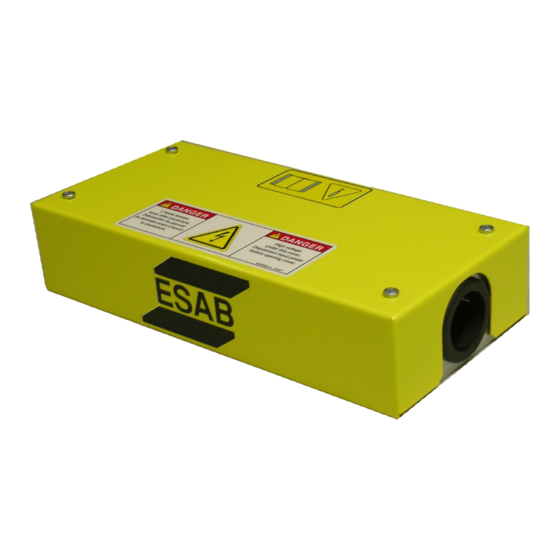
2.0 General The Remote Junction Box (RJB) provides a means to extend the total length of the PT-37 Torch. A Remote Junction Box is used in combination with 50’, 75' or 100’ extension cable and any standard length of PT-37 Plasma Torch from 4.5’ to 50’, to create a combined maximum torch length of 150 feet. - Página 18 SECTION 2 DESCRIPTION...
-
Página 19: Remote Junction Box Installation
3.0 Remote Junction Box Installation Installation of a Remote Junction Box requires minor modifications to the ESP-101 power supply, mounting of the box itself, and connection of the extension cable. Use the diagram and following steps for installation. 3-phase w/... -
Página 20: Esp-101 Modifications
The control signal is then diverted to the solenoid within the Remote Junction Box. The hose modification (solenoid air bypass) directs the system air supply to the solenoid within the Remote Junction Box. This ensures air at a sufficient pressure is immediately available to the PT-37 torch. -
Página 21: Mounting The Remote Junction Box (Rjb)
Replace the top and right side panel of the power supply. 3.2 Mounting the Remote Junction Box (RJB) 1. With the cover removed from the Remote Junction Box, mount the base to a rigid location on the cut- ting machine, robot, or other suitable object, using at least 2 of the provided mounting holes. Orient the box such that the Extension Cable will enter the end of the RJB not marked for torch connection. - Página 22 Note: Extension Cable connections from the ESP-101 must be connected on the solenoid wiring side of the To PT-37 Torch Remote junction Box. Torch Cable Air Connection (Torch connection side is labeled.) Extension Cable Power Connection...
-
Página 23: Connecting To The Esp-101
Extension Cable Lead Access Door 3. Connect the extension cable male receptacle (from Remote Junction Box) to the female receptacle. Check orientation of the sockets so as to ensure a correct fit. 4. Connect the air hose (from Remote Junction Box) to the quick-connect fitting. - Página 24 SECTION 4 OPERATION...
-
Página 25: General
SECTION 4 MAINTENANCE Be sure that the wall disconnect switch or wall circuit breaker WARNING is open before attempting any inspection or work inside of the UNIT. 4.0 General If this equipment does not operate properly, stop work immediately and investigate the cause of the malfunc- tion. -
Página 26: Troubleshooting
A volt-ohmmeter will be necessary for some of these checks. 5.1 Troubleshooting Remote Junction Box installation Issue Resolution Continuous flow of gas from Remote Junction Box. Extension Cable and Torch Cable are connected to wrong sides of RJB. Disconnect air supply and cables and reverse RJB mounting. -
Página 27: Replacement Parts
Always provide the part number of the unit on which the parts will be used. 6.2 Ordering To ensure proper operation, it is recommended that only genuine ESAB parts and products be used with this equipment. The use of non-ESAB parts may void your warranty. - Página 28 SECTION 6 REPLACEMENT PARTS Item Description 0558006396 VALVE SOLENOID 3-WAY 100 PSI 24VDC 0558005635 COUPLING BODY QD 1/4NPTM 993426 GROMMET RUBBER 1.50ID 1.75GD .06W SOL-1 TIGHTEN SO THAT DISCONNECT LATCH WILL NOT BE PRESSED WHEN COVER IS APPLIED. (12 O'CLOCK OR BETWEEN 3 &...
- Página 29 SECTION 6 REPLACEMENT PARTS NECT...
- Página 30 SECTION 6 REPLACEMENT PARTS...
-
Página 31: Revision History
REVISION HISTORY 1. Original release: 03/2011. - Página 32 IF YOU DO NOT KNOW WHOM TO CALL Telephone: (800) ESAB-123 Fax: (843) 664-4462 Hours: 7:30 AM to 5:00 PM EST Visit us on the web at http://www.esabna.com The ESAB web site offers Comprehensive Product Information Material Safety Data Sheets Warranty Registration Instruction Literature Download Library Distributor Locator...