Tabla de contenido
Publicidad
Idiomas disponibles
Idiomas disponibles
Enlaces rápidos
www.interface.phoenixcontact.com
Halbleiter-Wendeschütze
DE
Solid-State Reversing Contactor
EN
Contacteur d'inversion à semi-conducteurs
FR
Contactor inversor semiconductor
ES
ELR W3- 24DC/500AC-2I
ELR W3-230AC/500AC-2I
ELR W3- 24DC/500AC-9I
ELR W3-230AC/500AC-9I
3 2 8
2 5
w w
B l o
w . i
m b
e r g
n t e
S o
r f a
l i d -
s t a
I n p
t e r
u t :
2 4 V
D C
O u
t p u
4 2 -
t :
5 0 0
V A
C / 2
I E C
6 1 5
I S O
0 8 :
1 3 8
E N
S I L
4 9 -
3
9 5 4
1 : C
- 1 :
a t e
C a
t e g
o r y
X
I I ( 2
) G
P T
D
B
0 7
A T
E X
PHOENIX CONTACT GmbH & Co. KG
D-32823 Blomberg, Germany
Fax +49-(0)5235-341200, Phone +49-(0)5235-300
E L
, G
e r m
R W
c e .
O r d
a n y
3 - 2
p h
. - N
o e n
4 D
o . :
e v e
i x c
C / 5
2 2
r s i
o n
0 0 A
n g
9 7 0
t a c
c o n
C - 2
t . c o
3 1
t a c
I
m
t o r
/ H
a l b
l e i t
, 4 A
e r
9 7
- W
e n d
9 6 /
9 8
9 6 /
e s c
9 8
9 5
h ü
9 7
t z
R e
& E
s e t
9 5
r r o
r
A u
M A
t o r
N
g o
e s e
r y
t
3
R e
P L
R E
3
s e t
S
e
2
A U
U
T
L o
s
g i c
µ P
U
s
2 4
3 1 4
5
V D
E
C
R
L
2 4 V
D C
R e
s e t
© PHOENIX CONTACT 2008
3 2 8
2 5
w w
B l o
w . i
m b
e r g
n t e
S o
E L
, G
r f a
l i d -
e r m
R W
c e .
O r d
s t a
a n y
p h
I n p
. - N
t e r
o e n
e v e
u t :
i x c
2 4 V
r s i
o n
n g
D C
t a c
O u
c o n
t p u
t a c
4 2 -
t :
t o r
5 0 0
V A
C / 9
A
9 7
9 6 /
9 5
I E C
6 1 5
I S O
R e
0 8 :
1 3 8
s e t
E N
S I L
4 9 -
3
9 5 4
1 : C
A u
- 1 :
a t e
C a
g o
t e g
r y
o r y
L
3
P L
3
E
e
R
X
I I ( 2
T
A U
U
) G
P T
D
s
E S
B
9 5
U
S
0 7
N R
3
A T
1 , 6
9 6
E X
M A
3 1 4
9 7
5
2 , 4
E
R
7
0 , 8
L
1 / L
1
8
3 / L
0 , 1
A
2
2 , 4
5 / L
3
x .
2 / T
m a
1
4 / T
2
6 / T
R
P W
3
E r r
L
R
s e t
R e
3
5 / L
3
6 / T
2
3 / L
2
4 / T
1
1 / L
1
2 / T
MNR 9037067 / 05.2008
Art.-Nr.: 2297031
Art.-Nr.: 2297044
Art.-Nr.: 2297057
Art.-Nr.: 2297060
3 - 2
4 D
o . :
C / 5
2 2
0 0 A
9 7 0
C - 9
t . c o
5 7
I
m
/ H
a l b
l e i t
e r
- W
e n d
9 8
9 6 /
e s c
9 8
h ü
9 7
t z
& E
9 5
r r o
r
M A
t o r
N
e s e
t
R e
R E
s e t
S
2
A U
1 / L
T
L o
1
g i c
3 / L
µ P
U
2
s
2 4
5 / L
V D
3
C
2 / T
1
4 / T
2
2 4 V
6 / T
D C
3
R e
s e t
L
E
R
T
A U
E S
9 5
U
S
N R
6 , 5
9 6
M A
9 7
9 , 0
4 , 0
1 , 5
9 A
x .
m a
R
P W
E r r
L
R
s e t
R e
3
5 / L
3
6 / T
2
3 / L
2
4 / T
1
1 / L
1
2 / T
Publicidad
Tabla de contenido

Manuales relacionados para Phoenix Contact ELR W3- 24DC/500AC-2I


Resumen de contenidos para Phoenix Contact ELR W3- 24DC/500AC-2I
- Página 1 PHOENIX CONTACT GmbH & Co. KG D-32823 Blomberg, Germany Fax +49-(0)5235-341200, Phone +49-(0)5235-300 www.interface.phoenixcontact.com MNR 9037067 / 05.2008 Halbleiter-Wendeschütze Solid-State Reversing Contactor Contacteur d’inversion à semi-conducteurs Contactor inversor semiconductor ELR W3- 24DC/500AC-2I Art.-Nr.: 2297031 ELR W3-230AC/500AC-2I Art.-Nr.: 2297044 ELR W3- 24DC/500AC-9I Art.-Nr.: 2297057...
-
Página 2: Tabla De Contenido
Inhaltsverzeichnis Seite 1. Kurzbeschreibung..................4 2. Sicherheitsbestimmungen / Errichtungshinweise ........5 3. Anschlusshinweise 3.1. Netzanschluss und Leitungsschutz............6 3.2. Blockschaltbild..................6 4. Funktion 4.1. Bedienung und Betriebsarten ..............7 4.2. Parametrierung / Nennstromeinstellung........... 7 4.3. Fehlererkennung..................8 5. Applikationsbeispiele - Beschreibung ............10 6. Technische Daten ..................11 7. - Página 3 Sommaire Page 1. Description succincte................28 2. Contraintes de sécurité / Instructions d'installation ........29 3. Conseils pour le raccordement 3.1. Raccordement au réseau et protection de ligne........30 3.2. Schéma fonctionnel ................30 4. Fonctionnement 4.1. Commande et modes de fonctionnement ..........31 4.2. Paramétrage / Réglage de l'intensité nominale ........31 4.3.
-
Página 4: Kurzbeschreibung
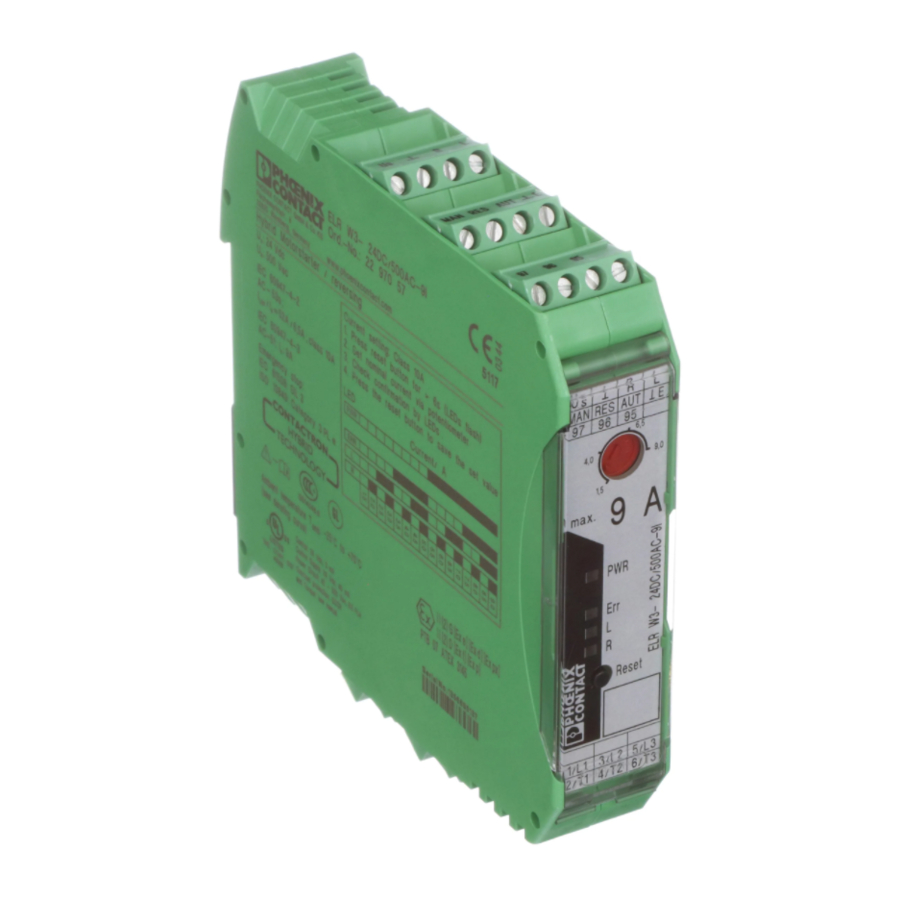
DEUTSCH Halbleiter-Wendeschütz ELR W3-.../500AC-...I Steuereingang: Eingang: Rechtslauf/Linkslauf Bemessungssteuer- GNDE: Bezugspunkt speisespannung Rechtslauf/Linkslauf Quittierungseingänge MAN, RES, AUT Rückmeldung 3 2 8 B l o w . i e r g n t e r f a l i d - e r m c e . -
Página 5: Sicherheitsbestimmungen / Errichtungshinweise
2. Sicherheitsbestimmungen / Errichtungshinweise • Beachten Sie bei allen Arbeiten am Gerät die na- EN 50281 eingebaut werden. tionalen Sicherheits- und Unfallverhütungsvor- • Der Einbau hat gemäß den in der Betriebsanlei- schriften. tung beschriebenen Anweisungen zu erfolgen. • Werden die Sicherheitsvorschriften nicht beach- Ein Zugriff auf die Stromkreise im Inneren des Ge- tet, können Tod, schwere Körperverletzung rätes ist während des Betriebes nicht zugelassen. -
Página 6: Anschlusshinweise
3. Anschlusshinweise 3.1. Netzanschluss und Leitungsschutz Vorsicht: Niemals bei anliegender Spannung arbeiten! Lebensgefahr! • Beim Anschluss des 3-Phasen-Netzes ist unbedingt die Klemmenbezeichnung zu beachten! • Absicherung: 25 A (Diazed) - Leitungsschutz bei max. Leitungsquerschnitt 2,5 mm 16 A FF (6,3 x 32 mm) - Geräteschutz 16 A (Automat B, Leitungsschutzschalter) - Kurzschluss (1,5 kA-Netz) 20 A (Motorschutzschalter) -... -
Página 7: Funktion
4. Funktion 4.1. Bedienung und Betriebsarten 4.1.1. Status LEDs LED PWR Gerätestatus Mit insgesamt vier LEDs visualisiert das (grün) Halbleiter-Wendeschütz die Betriebszu- Keine Versorgungsspannung stände. Die Funktionen der LEDs orientie- (Bemessungssteuerspeisespannung). ren sich an der NAMUR-Empfehlung NE 44. Versorgungsspannung (Bemessungs- steuerspeisespannung) vorhanden Nach Anlegen der Bemessungssteuerspei- sespannung leuchten sämtliche LEDs als... -
Página 8: Fehlererkennung
4.3. Fehlererkennung Durch diverse Diagnosefunktionen ist das Halbleiter-Wendeschütz nicht nur in der Lage, viele interne Fehler, sondern auch externe Fehler (Fehler in der Peripherie) zu erkennen. Alle internen Fehler sind nicht quittierbar und werden im Gerät gespeichert. Das Gerät kann anschließend nicht wieder in Betrieb genommen werden. - Página 9 4.3.1. Fehlerquittierung Für die Fehlerquittierung stehen drei verschiedene Möglichkeiten zur Verfügung: Manuell (Reset-Taster): Eine Quittierung wird durch eine Betätigung des Reset-Tasters an der Geräte- Frontseite ausgelöst. Wird nach Ablauf einer Zeit von ca. 2 s der Reset-Taster immer noch betätigt, nimmt das Halbleiter-Wen- deschütz wieder den Fehlerzustand ein.
-
Página 10: Motor Mit Bremse
5.3. Motorschutz Der Einsatz des Halbleiter-Wendeschützes im Bereich des Motorschutzes gestaltet sich denkbar einfach: Alle für die Sicherheit relevanten Funktionen werden ohne äußeren Einfluss durch das Halbleiter-Wende- schütz realisiert. Besondere Schaltungstechniken sind nicht notwendig. Die Verdrahtung des Laststromkreises sollte wie in den oben aufgeführten Beispielen realisiert werden. Der Anschluss der Modulstromversorgung kann aber im Gegensatz dazu direkt an der Spannungsquelle erfolgen, ohne Sicherheitsrelais PSR. -
Página 11: Technische Daten
6. Technische Daten Rückmeldeausgang Kontaktausführung Einfachkontakt, 1 Wechsler Kontaktmaterial Ag-Legierung, hartvergoldet Max. Schaltspannung 30 V AC / 36 V DC (250 AC/DC) Min. Schaltspannung 100 mV (12 V AC/DC) Grenzdauerstrom 50 mA (6 A) Min. Schaltstrom 1 mA Max. Abschaltleistung, ohmsche Last 24 V DC 1,2 W (140 W) - Página 12 6. Technische Daten Allgemeine Daten Netzfrequenz 40...100 Hz Max. Schaltfrequenz 2 Hz Bemessungsstoßspannung zwischen 6 kV (ELR W3-24DC/...) Steuereingangs-, Bemessungssteuerspeise - und Schaltspannung • Netznennspannung (≤ 500 V AC) Sichere Trennung (EN 50178) • Netznennspannung (≤ 300 V AC, Sichere Trennung (IEC 60947-1) z.B.230/400 V AC, 277/480 V AC) •...
- Página 13 6.1. Auslösekennlinie bei 20 °C (Blockierschutz) Auslösekennlinie Max. Min. Überstromfaktor 6.2. Deratingkurven bei 100 % Einschaltdauer (Weitere Daten auf Anfrage) ELR W3-24DC/... Laststrom 9 A: = angereit mit Abstand von 20 mm = angereit ohne Abstand Laststrom 2,4 A: = angereit mit Abstand von 20 mm = angereit ohne Abstand 0,18 [°C]...
-
Página 14: Sicherheitstechnische Funktionen
7. Sicherheitstechnische Funktionen Systembedingungen Datenbank für Ausfallraten SN 29500 Systemtyp Typ B, bestehend aus Subsystemen Angewandte Norm IEC 61508 Beta-Faktor 7.1. Sicheres Abschalten ELR W3-24DC/500AC-... ELR W3-230AC/500AC-... Umgebungstemperatur 40 °C 60 °C 40 °C 60 °C MTTF [Jahre] Mean time to failure 45,6 23,0 46,0... - Página 15 7.3. Sicheres Abschalten (Kennlinie) bei 40 °C Umgebungstemperatur ELR W3-24DC/... (Bauteiltemperatur 60 °C) ELR W3-230AC/... 0,0035 bei 60 °C Umgebungstemperatur (Bauteiltemperatur 80 °C) 0,003 bei 60 °C Umgebungstemperatur (Bauteiltemperatur 80 °C), 0,0025 max. Einschaltdauer 2 Jahre 0,002 0,0015 0,001 0,0005 10 11 12 13 14 15 16 17 18 19 20 Jahre 7.4.
-
Página 16: Short Description
ENGLISH Solid-state reversing contactor ELR W3-.../500AC-...I Control input: Forward running/Reverse running Input: Rated control supply GNDE: Reference point voltage Forward running/Reverse running Acknowledgment inputs MAN, RES, AUT Feedback 3 2 8 B l o w . i e r g n t e r f a l i d -... -
Página 17: Safety Regulations / Installation Notes
2. Safety regulations / Installation notes • When working on the device, observe the national and must be replaced by an equivalent. Repairs safety and accident prevention regulations. can only be carried out by the manufacturer. • Ignoring the safety regulations can lead to death, •... -
Página 18: Mains Connection And Line Protection
3. Connection notes 3.1. Mains connection and line protection Danger! Never carry out work on live parts! Danger to life! • When connecting the 3-phase network, it is essential to observe the terminal identification! • Protection: 25 A (Diazed) - Line protection at a max. -
Página 19: Function
4. Function 4.1. Operation and operating modes 4.1.1. Status LEDs "PWR" LED Device status The solid-state reversing contactor displays (green) the operating conditions with a total of four No supply voltage LEDs. The functions of the LEDs are based (rated control supply voltage) on the NAMUR recommendation NE 44. -
Página 20: Error Detection
4.3. Error Detection The solid-state reversing contactor is not only capable to detect many internal errors, but also external error (peripheral errors) by various diagnostics functions. All internal errors cannot be acknowledged and are stored in the device. The device then cannot be started again. The operating conditions are displayed by LEDs. -
Página 21: Application Examples - Description
4.3.1. Error acknowledgment Three separate options are available for the error acknowledgment: Manual (reset button): An acknowledgment is triggered by activating the reset button on the front of the device. If the reset button is still activated after the end of approx. 2 s, the solid-state reversing contactor will return to the error state. -
Página 22: Motor Protection
5.3. Motor Protection Using the solid-state reversing contactor in the area of the motor protection is designed as simple as possible: Functions relevant for safety are realized by the solid-state reversing contactor without any ex- ternal influences. Special switching techniques are not required. The wiring of the load current circuit should be implemented as in the above listed examples. -
Página 23: Technical Data
6. Technical data Reply output Contact type Single contact, 1 PDT Contact material Ag alloy, hard gold-plated Max. switching voltage 30 V AC / 36 V DC (250 AC/DC) Min. switching voltage 100 mV (12 V AC/DC) Limiting continuous current 50 mA (6 A) Min. - Página 24 6. Technical data General data Mains frequency 40...100 Hz Max. switching frequency 2 Hz Rated surge voltage 6 kV (ELR W3-24DC/...) between Control input-, rated control supply- and switching voltage • Mains nominal voltage (≤ 500 V AC) safe isolation (EN 50178) •...
- Página 25 6.1. Tripping characteristics for 20 °C (blocking protection) Tripping characteristics Max. Min. Overload current factor 6.2. Derating curves for 100 % operating time (more data available on request) ELR W3-24DC/... Load current 9 A: = in rows with spacing of 20 mm = in rows with zero spacing Load current 2,4 A: = in rows with spacing of 20 mm...
-
Página 26: Safety Functions
7. Safety functions System requirements Database for failure rates SN 29500 System type Type B, consisting of sub-systems Applied standard IEC 61508 Beta factor 7.1. Safe switch-off ELR W3-24DC/500AC-... ELR W3-230AC/500AC-... Ambient temperature 40°C 60°C 40°C 60°C MTBF [years] Mean time to failure 45.6 23,0 46.0... - Página 27 7.3. Safe switch-off (characteristics) at ambient temperature 40 °C ELR W3-24DC/... (component temperature 60 °C) ELR W3-230AC/... 0,0035 at ambient temperature 60 °C (component temperature 80 °C) 0,003 at ambient temperature 60 °C (component temperature 80 °C), 0,0025 max. operating time 2 years 0,002 0,0015 0,001...
-
Página 28: Brève Description
FRANÇAIS Contacteur d’inversion à semi-conducteur ELR W3-.../500AC-...I Entrée de commande : Entrée : Rotation à droite/gauche Tension d’alimentation de commande assignée GNDE : point de référence Rotation à droite/gauche Entrées d'acquittement MAN, RES, AUT Accusé de réception 3 2 8 B l o w . -
Página 29: Contraintes De Sécurité / Instructions D'installation
2. Contraintes de sécurité / Instructions d'installation • Respectez les directives nationales de sécurité et dans un boîtier adéquat (minimum IP64) selon EN de prévention des accidents 50281. pour tous les travaux sur les appareils. • Le montage doit être réalisé selon les instructions •... -
Página 30: Conseils Pour Le Raccordement
3. Conseils de raccordement 3.1. Raccordement au réseau et protection de ligne Attention : Ne jamais travailler sur un module sous tension ! Danger de mort ! • Lors du raccordement au réseau triphasé, reportez-vous obligatoirement au repérage de BJ ! •... -
Página 31: Fonctionnement
4. Fonctionnement 4.1. Commande et modes de fonctionnement 4.1.1. LED d'état LED PWR (verte) Etat de l'appareil Le contacteur d’inversion à semi-conduc- Désactivée Pas d'alimentation (tension d'alimentati- teurs visualise les états de fonctionnement à on de commande assignée) l'aide de 4 LED au total. Les fonctions des LED s'orientent sur la recommandation Activée Alimentation (tension d'alimentation de... -
Página 32: Détection De Défaut
4.3. Détection de défaut Grâce à diverses fonctions de diagnostic, le contacteur d’inversion à semi-conducteur n'est pas unique- ment en mesure de détecter un grand nombre d'erreurs internes, mais également des erreurs externes (erreur au niveau de la périphérie). Toutes les erreurs internes ne sont pas acquittables et sont enregist- rées dans l'appareil. -
Página 33: Accusé De Réception
4.3.1. Acquittement de l'erreur Trois différentes possibilités sont disponibles pour l'acquittement de l'erreur : manuel (bouton Reset) : L'acquittement est déclenché par l'actionnement du bouton Reset situé sur la face avant de l'appareil. Si après l'écoulement d'une période d'environ 2 s, le bouton Reset est toujours actionné, le contacteur d’inversion à... -
Página 34: Protection Du Moteur
5.3. Protection du moteur L'utilisation du contacteur d’inversion à semi-conducteurs dans le domaine de la protection du moteur est d'une extrême simplicité : Toutes les fonctions concernant la sécurité sont réalisées sans influence exté- rieure générée par le contacteur d’inversion à semi-conducteurs. Aucune technique de commutation spé- ciale n'est nécessaire. -
Página 35: Caractéristiques Techniques
6. Caractéristiques techniques Sortie de report d'information Type de contact Contact simple, 1 inverseur Matériau des contacts Alliage Ag, revêtement or dur Tension de commutation max. 30 V AC / 36 V DC (250 AC/DC) Tension de commutation min. 100 mV (12 V AC/DC) Intensité... - Página 36 6. Caractéristiques techniques Caractéristiques générales Fréquence du réseau 40...100 Hz Fréquence de commutation max. 2 Hz Tension de choc assignée entre 6 kV (ELR W3-24DC/...) Tension d‘entrée de commande, tension d’alimentation de commande assignée et tension de commutation • Tension nominale du réseaux (≤ 500 V AC) isolement sécurisé...
-
Página 37: Courbe De Déclenchement À 20 °C (Protection De Blocage)
6.1. Courbe de déclenchement à 20 °C (protection de blocage) Courbe de déclenchement Max. Min. Facteur de surintensité 6.2. Courbes de derating à 100 % de la durée d'enclenchement (autres données sur demande) ELR W3-24DC/... Courant de charge 9 A: = juxtaposé... -
Página 38: Fonctions Techniques De Sécurité
7. Fonctions techniques de sécurité Conditions du système Base de données pour tx de défaillance SN 29500 Type système Type B, composé à partir de sous-systèmes Norme appliquée CEI 61508 Facteur Bêta 7.1. Déconnexion sûre ELR W3-24DC/500AC-... ELR W3-230AC/500AC-... Température ambiante 40 °C 60 °C 40 °C... - Página 39 7.3. Déconnexion sûre (courbe caractéristique) avec une température ambiante de 40 °C ELR W3-24DC/... (température des composants 60 °C) ELR W3-230AC/... 0,0035 avec une température ambiante de 60 °C (température des composants 80 °C) 0,003 avec une température ambiante de 60 °C (température des composants 80 °C), 0,0025 durée d’enclenchement max.
-
Página 40: Descripción Resumida
ESPAÑOL Contactor inversor semiconductor ELR W3-.../500AC-...I Entrada: Entrada de mando: tensión de alimentación de giro a la derecha/izquierda control de dimensionamiento GNDE: punto de referencia giro a la derecha/izquierda Entradas de acuse de recibo MAN, RES, AUT Acuse de recibo 3 2 8 B l o w . -
Página 41: Prescripciones De Seguridad / Indicaciones De Instalación
2. Prescripciones de seguridad / indicaciones de instalación • Observe, en todos los trabajos a realizar en el mó- ne que disponerse en una caja apropiada (como dulo, las prescripciones nacionales de seguridad mínimo IP64) según EN 50281. y para la prevención de accidentes. •... -
Página 42: Indicaciones De Conexión
3. Indicaciones de conexión 3.1. Conexión a la red y protección de línea Atención: ¡No trabajar nunca con la tensión conectada! ¡Peligro de muerte! • Para conectar la red trifásica debe observarse incondicionalmente la denominación de los bornes. • Protección por fusibles: 25 A (Diazed) - Protección de línea para sección máx. -
Página 43: Función
4. Función 4.1. Operación y tipos de servicio 4.1.1. Estado de los LED´s LED PWR (verde)Estado del módulo El contactor inversor semiconductor visua- Apagado No hay tensión de alimentación (tensión liza los estados de servicio con cuatro de alimentación de control de dimension- LED´s. -
Página 44: Detección De Error
4.3. Detección de error Mediante diversas funciones de diagnóstico, el contactor inversor semiconductor no sólo detecta múltip- les errores internos sino también errores externos (errores en la periferia). A todos los errores internos no puede dárseles acuse de recibo y se almacenan en el módulo. En este caso, el módulo no puede ponerse en servicio de nuevo. -
Página 45: Acuse De Recibo De Error
4.3.1. Acuse de recibo de error Para el acuse de recibo de error se dispone de tres posibilidades diferentes: Manual (pulsador Reset): Un acuse de recibo se activa mediante el accionamiento del pulsador Reset dispuesto en el frontal del módulo. Si después de un tiempo aprox. -
Página 46: Motor Con Freno
5.3. Guardamotor El uso del contactor inversor semiconductor en el sector del guardamotor es realmente sencillo: Todas las funciones relevantes para la seguridad se realizan sin influencia exterior a través del contactor inversor semiconductor. No se precisan técnicas de circuitos especiales. El cableado del circuito de corriente de carga debe realizarse tal como se indica en los ejemplos arriba mencionados. -
Página 47: Datos Técnicos
6. Datos técnicos Salida de acuse de recibo Tipo de contacto contacto simple, 1 contacto conmutado Material del contacto aleación de Ag, dorado duro Tensión máx. de activación 30 V AC / 36 V DC (250 AC/DC) Tensión mín. de activación 100 mV (12 V AC/DC) Corriente constante límite... - Página 48 6. Datos técnicos Datos generales Frecuencia de red 40...100 Hz Frecuencia máx. de conmutación 2 Hz Tensión transitoria de dimensionamiento entre 6 kV (ELR W3-24DC/...) Tensión de entrada de mando, tensión de alimentación de control de dimensionamiento y tensión de conexión •...
-
Página 49: Curva Característica De Disparo Para 20 °C (Protección De Bloqueo)
6.1. Curva característica de disparo para 20 °C (protección de bloqueo) Curva característica de disparo máx. mín. Factor de sobrecorriente 6.2. Curvas derating para duración de conexión del 100 % (otros datos bajo consulta) ELR W3-24DC/... Corriente de carga 9 A: = alineado con separación de 20 mm = alineado sin separación Corriente de carga 2,4 A:... -
Página 50: Funciones Técnicas De Seguridad
7. Funciones técnicas de seguridad Condiciones del sistema Banco de datos para rangos de fallo SN 29500 Tipo de sistema tipo B, compuesto de sistemas subordinados Norma empleada IEC 61508 Factor beta 7.1. Desconexión segura ELR W3-24DC/500AC-... ELR W3-230AC/500AC-... Temperatura ambiente 40 °C 60 °C 40 °C... - Página 51 7.3. Desconexión segura (curva característica) con una temperatura ambiente de 40 °C ELR W3-24DC/... (temperatura de los componentes 60 °C) ELR W3-230AC/... 0,0035 con una temperatura ambiente de 60 °C (temperatura de los componentes 80 °C) 0,003 con una temperatura ambiente de 60 °C (temperatura de los componentes 80 °C), 0,0025 duración de conexión 2 años...
-
Página 52: Applikationsbeispiele - Schaltungen
8.1. Schaltbeispiel / Example circuit / Exemple de circuit / Ejemplo de circuito "NOT-HALT (einkanalig)" (nach Kat. 3, SIL 3, PL e): ELR W 3-.../500AC-...I mit übergeordneter Sicherheitsrelais-Kombination innerhalb eines geschlossenen Schaltschrankes. Zum Erreichen der maximalen Lebensdauer, falls möglich Beispiele ab Seite 54 anwenden! "EMERGENCY STOP (single channel)"... - Página 53 8.2. Schaltbeispiel / Example circuit / Exemple de circuit / Ejemplo de circuito "NOT-HALT (zweikanalig)" (nach Kat. 3, SIL 3, PL e): ELR W 3-.../500AC-...I mit übergeordneter Sicherheitsrelais-Kombination. Zum Erreichen der maximalen Lebensdauer, falls möglich Beispiele ab Seite 54 anwenden! "EMERGENCY STOP (two channels)"...
- Página 54 8.3. Schaltbeispiel / Example circuit / Exemple de circuit / Ejemplo de circuito "Schutztür / Zweihand-/NOT-AUS-Applikation (einkanalig)" (nach Kat. 3, SIL 3, PL e): ELR W 3-.../500AC-...I mit übergeordneter Sicherheitsrelais-Kombination "Safety door / two-hand / EMERGENCY STOP application (single channel)" (acc.
- Página 55 8.4. Schaltbeispiel / Example circuit / Exemple de circuit / Ejemplo de circuito "Schutztür / Zweihand-/NOT-AUS-Applikation (zweikanalig)" (nach Kat. 3, SIL 3, PL e): ELR W 3-.../500AC-...I mit übergeordneter Sicherheitsrelais-Kombination "Safety door / two-hand / EMERGENCY STOP application (two channels)" (acc.
- Página 56 PHOENIX CONTACT GmbH & Co. KG D-32823 Blomberg, Germany Fax +49-(0)5235-341200 Phone +49-(0)5235-300 www.phoenixcontact.com...