
Manuales relacionados para Megger DET2/2


Resumen de contenidos para Megger DET2/2
- Página 1 DET2/2 Digital Earth Tester USER GUIDE GUIDE DE L’UTILISATEUR GEBRAUCHSANLEITUNG GUÍA DEL USUARIO...
-
Página 2: Safety Warnings
• Replacement fuses must be of the correct type and rating • Before charging the DET2/2 battery ensure that the correct supply fuse is fitted and the voltage selector is set correctly. • Warnings and precautions must be read and understood before the instrument is used. They must be observed during use. -
Página 3: Tabla De Contenido
Contents Guide de l’utilisateur p43 Gebrauchsanleitung s67 Guía del usuario Measuring soil resistivity - Safety Warnings Typical variations in soil resistivity Contents Line traverse General Description Calculation of Resistivity Applications Continuity Testing Features and Controls Specification Initial Configuration Accessories Setting up Test spikes Chart for use with Slope method Repair and Warranty Earth Testing Safety Precautions... -
Página 4: General Description
LCD display are mounted on the front panel. Display language can be selected from English, DET2/2 is splash proof, and suitable for outdoor use French, German, Portuguese or Spanish. A range of in most weather conditions. -
Página 5: Applications
It is possible with checking the resistance of conductors used in an DET2/2 to obtain the resistivity of the soil over an area earthing circuit. and at different levels beneath the surface of the ground. -
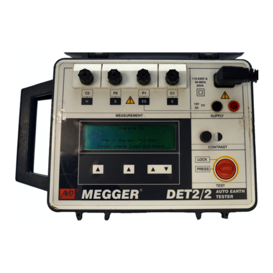
Página 6: Features And Controls
Features and Controls To electrode under test (Potential connection) To Potential test spike To electrode under test To Current test spike (Current connection) Charger socket ⁄ digit L.C.D. External 12 V d.c. supply Terminals Display contrast adjustment On / Off Test Button (Rotate clockwise to lock) Test control... -
Página 7: Initial Configuration
Initial Configuration Default Language Setting Select and set the default Frequency as follows: Select and set the display language default as follows: Using the centre ▲ key, scroll through the Press the left hand key ▲ and the TEST button Frequency options. -
Página 8: Setting Up Test Spikes
Setting up the Test spikes For earth electrode testing and for earth resistivity surveying, the instrument’s test leads are connected to spikes inserted in the ground. The way the connections are made depends on the type of test being undertaken and details are given in ‘Measuring Techniques’. -
Página 9: Earth Testing Safety Precautions
‘Live’ earth safety precautions of which will cope with the maximum fault The DET2/2 allows earth testing to be done at a voltage and current. The isolation switch must relatively safe voltage using a maximum of a 50 V RMS be open whilst any personal contact is made square wave at a frequency of nominally 128 Hz. - Página 10 Earth Testing Safety Precautions If isolation switches cannot be used, the leads should be disconnected from the instrument before remote spikes and leads are handled. When the remote connections have been made, the final connections should be made to the instrument using insulated plugs, ensuring that the Operator takes adequate and appropriate precautions such as insulating mats, rubber gloves etc.
-
Página 11: Operation
General Testing Procedure can be altered to achieve optimum conditions for the It is advisable that the battery of the DET2/2 is fully test. One or more of the following may be used:- charged before embarking on a test sequence. It can... -
Página 12: Display Messages
Operation resistance check of the of the Potential circuit. After a Display Messages short pause, the result of this check is displayed on the When appropriate, messages are displayed. The sub panel. If appropriate, the ‘Pspike‘ label then following message definitions are given: changes to ‘Retest’, giving the option to repeat the test “Please wait...”... -
Página 13: Error Messages
If the measurement to be invalid. Changing the test an error message appears, switch the DET2/2 off, frequency will have no effect in this instance. If refer to ‘Repair and Warranty’ and return the... - Página 14 Operation unsuccessful, switch the DET2/2 off, refer to ’Repair and Warranty’ and return the instrument to the manufacturer or approved agent, giving details of the error message and the software edition.
-
Página 15: Battery Charging
Battery Charging Battery capacity Disconnect and remove the test leads. The capacity of the battery is continuously monitored Connect the mains supply to the IEC 320 and displayed, adjacent to the battery symbol. The connector on the top right of the instrument. indicator segments will show fully charged, or recede Confirm that the message “Charging On”... - Página 16 Battery Charging Battery Charging Power cord plug Battery Charging Notes If the power cord plug is not suitable for your type of Do Not leave battery in a totally discharged state. socket, do not use an adaptor. You should use a If the instrument is idle for long periods, recharge suitable alternative power cord, or if necessary, change the battery at least every 6 months.
-
Página 17: Measuring Techniques Testing Earth Electrodes
Measuring Techniques - Testing Earth Electrodes FALL-OF-POTENTIAL METHOD This is the basic method for measuring the resistance of earth electrode systems. However, it may only be practical on small, single earth electrodes because of limitation on the size of area available to perform the tests. -
Página 18: The 61,8% Rule
Measuring Techniques - Testing Earth Electrodes Fall-of-Potential Method with Short 'E' Lead THE 61,8% RULE Another way of making connections to the earth To obtain an accurate reading using the Fall-of- electrode is to connect to the earth electrode using only Potential method the current spike must be correctly one single connection to the ‘C1’... - Página 19 This is the 61,8% Rule and strictly applies only when medium size containing several rods, then these the earth electrode and Current and Potential spikes lie distances must be increased. The following table gives in a straight line, when the soil is homogeneous and a range of distances that agree with the rule.
-
Página 20: The Slope Method
Measuring Techniques - Testing Earth Electrodes THE SLOPE METHOD 'P2' terminal. The test spikes and the earth system This method is more applicable to larger earth should all be in a straight line. electrode systems or where the position of the centre of The 'C1' and 'P1' terminals are connected separately the earthing system is not known or inaccessible (e.g. - Página 21 Suppose the distance from the earth electrode system (ii) If it is necessary, further sets of test results can be to the current spike is EC. From the curve equivalent obtained with different values of EC, or different resistance readings to Potential positions 0,2EC, 0,4EC directions of the line of EC.
-
Página 22: Method Using 'Dead' Earth
Measuring Techniques - Testing Earth Electrodes METHOD USING A ‘DEAD’ EARTH The resistance of the two test leads can be found by The techniques using test spikes explained earlier are firmly joining their free ends together, pressing the Test the preferred methods of earth testing. In congested push and taking the reading in the usual way. -
Página 23: Bs7671 (16Th Edition Iee Wiring Regulations) Requirements
Regulation 713-11 of BS7671 specifies that the among which are the Four Potential, Intersecting Curves resistance of earth electrodes must be measured. The and Star Delta methods. Megger Limited publications accompanying Guidance Notes describe a method of explain these test methods and give other helpful test that is very similar to the Fall-of-Potential method. -
Página 24: Determining 'Touch' Potential
Measuring Techniques - Testing Earth Electrodes Determining ‘Touch’ Potential ‘Touch’ potential is the potential difference a person would experience across his body if he were, for example, standing on the ground outside the earthed SUBSTATION perimeter fence of a substation and touching the fence at the time a fault occurred. -
Página 25: Determining 'Step' Potential
Determining ‘Step’ potential ‘Step’ potential is the potential difference a person would experience between his feet as he walked across SUBSTATION the ground in which a fault current was flowing. Firmly connect the instrument as follows :- Terminal 'C1' to the substation earth. Earth Terminal 'C2' to the Current spike inserted in the ground some distance away. -
Página 26: Typical Variations In Soil Resistivity
Measuring Techniques - Measuring Soil Resistivity Typical variations in soil resistivity Because it is impossible to forecast the resistivity of the The resistance to earth of an earth electrode is soil with any degree of accuracy it is important to influenced by the resistivity of the surrounding soil. -
Página 27: Line Traverse
By this means depth surveys may be made. More details can be found in the Megger Limited publications. See ‘Accessories‘. Calculation of resistivity Assuming that the tests were carried out in homogeneous soil the resistivity is given by the Soil resistivity measurement. - Página 28 Measuring Techniques - Measuring Soil Resistivity Resistivity calculation Nomogram...
-
Página 29: Continuity Testing
Measuring Techniques - Continuity Testing DET 2/2 can be used to measure metallic resistances of low inductance or capacitance. To test the continuity of conduit or other earth conductors the instrument can be connected as shown. Ensure that the circuit is de- energised, before connecting the instrument for measurement. -
Página 30: Specification
Specification Earth Resistance Ranges: 0,010 Ω to 19,99 kΩ (Auto-ranging) 1 mΩ resolution Accuracy (23°C ±2°C): ±0,5% of reading ±2 digits. Service error ±5% of reading ±2 digits ±10 mΩ (meets VDE service error over 50 mΩ) Test Frequency: 105 Hz to 160 Hz reversing d.c. (50 Hz environments default to 128 Hz, 60 Hz environments default to 150 Hz). - Página 31 Display: Alpha numeric LCD (130 mm x 35 mm) giving test information and a large (20 mm) 3 ⁄ digitLCD, maximum reading 1999 Instrument Protection: Meets the general requirements of IP54 Temperature Effect: <±0,1%/°C over the temperature range -10°C to +40°C Temperature Range: Operating: -10°C to +40 °C...
- Página 32 3 Amp fuse to BS 1362 Safety: Meets the requirements for safety to IEC 61010-1 E.M.C: In accordance with IEC61326-1 Operational uncertainties: Visit www.megger.com Dimensions: 344 mm x 245 mm x 158 mm Weight: 5 kg Cleaning: Wipe the disconnected instrument with a clean cloth dampened with...
- Página 33 Note: This table can only be used for readings from a Resistance value column is correct for resistance DET2/2. readings < 2 Ω. For the 2 Ω to 20 Ω column and the > 20 Ω column, the decimal point should be moved accordingly.
- Página 34 Specification Maximum Maximum Reading Maximum Maximum Reading Resistance Resistance < 2 to 20 > 20 < 2 to 20 > 20 Value Value 0,050 0,036 1,100 1,036 10,45 104,5 0,100 0,083 1,150 1,083 10,92 109,3 0,150 0,131 1,200 1,131 11,40 114,0 0,200 0,179...
-
Página 35: Accessories
Accessories SUPPLIED Part Number U.S. OPTIONS Cat. Number Standard Accessory kit 250579 User Guide 6171-428 Canvas case containing:- Battery charging Power cord 2 x 20 in rods, leads (25,50 &100 ft) OPTIONAL Deluxe Accessory kit 250581 Publications ‘Getting Down to Earth’ AVTM25-TA Padded case to hold instrument, 2 x 20 in rods, leads... -
Página 36: Chart For Use With Slope Method
Chart for use with the Slope Method Values of P t / EC for Values of μ μ 0.40 0.6432 0.6431 0.6429 0.6428 0.6426 0.6425 0.6423 0.6422 0.6420 0.642 0.41 0.6418 0.6417 0.6415 0.6414 0.6412 0.6411 0.641 0.6408 0.6407 0.6405 0.42 0.6404 0.6403... - Página 37 μ 0.64 0.6072 0.6071 0.6069 0.6068 0.6066 0.6064 0.6063 0.6061 0.606 0.6058 0.65 0.6056 0.6055 0.6053 0.6052 0.605 0.6048 0.6047 0.6045 0.6043 0.6042 0.66 0.604 0.6039 0.6037 0.6035 0.6034 0.6032 0.6031 0.6029 0.6027 0.6026 0.67 0.6024 0.6022 0.6021 0.6019 0.6017 0.6016 0.6014 0.6013...
- Página 38 Chart for use with the Slope Method (continued) μ 0.90 0.5618 0.5616 0.5614 0.5612 0.561 0.5608 0.5606 0.5604 0.5602 0.56 0.91 0.5598 0.5596 0.5595 0.5593 0.5591 0.5589 0.5587 0.5585 0.5583 0.5581 0.92 0.5579 0.5577 0.5575 0.5573 0.5571 0.5569 0.5567 0.5565 0.5563 0.5561 0.93...
- Página 39 μ 1.16 0.5046 0.5043 0.5041 0.5038 0.5036 0.5033 0.5031 0.5028 0.5025 0.5023 1.17 0.502 0.5018 0.5015 0.5013 0.501 0.5007 0.5005 0.5002 0.4997 1.18 0.4994 0.4992 0.4989 0.4987 0.4984 0.4981 0.4979 0.4976 0.4973 0.4971 1.19 0.4968 0.4965 0.4963 0.496 0.4957 0.4955 0.4952 0.4949 0.4947...
- Página 40 Chart for use with the Slope Method (continued) μ 1.42 0.4232 0.4228 0.4225 0.4221 0.4217 0.4213 0.4209 0.4205 0.4201 0.4197 1.43 0.4193 0.4189 0.4185 0.4181 0.4177 0.4173 0.4168 0.4164 0.416 0.4156 1.44 0.4152 0.4148 0.4144 0.414 0.4136 0.4131 0.4127 0.4123 0.4119 0.4115 1.45...
-
Página 41: Repair And Warranty
Megger instruments, using genuine Megger spare parts. suitably trained and qualified personnel. The protection is Consult the Appointed Distributor/Agent regarding spare... -
Página 43: Guide De L'utilisateur
DET2/2 Contrôleur de masse numérique Guide de l’utilisateur... -
Página 44: Avertissements Relatifs À La Sécurité
Les fusibles de remplacement doivent être du type et de la puissance corrects. • Avant de charger la batterie du DET2/2 vérifier que le fusible d’alimentation correct est installé, et que • Les Avertissements et les Précautions doivent être lus et compris avant d’utiliser l’instrument. Ils doivent être observés pendant l’usage. -
Página 45: Table Des Matières
Table des matière User Guide p2 Gebrauchsanleitung Guía del usuario Avertissements relatifs à la sécurité Table des matières Description générale Applications Symboles utilisés sur cet instrument Caractéristiques et commandes Attention: Consultez les notes Configuration initiale jointes. Mise en place des piquets d’essai Précautions de sécurité... -
Página 46: Description Générale
Description générale Le Megger DET2/2 est un instrument portable compact et sens inverse des aiguilles d’une montre et le relâcher. autonome destiné à mesurer la résistance des électrodes L’affichage LCD peut être ajusté en tournant le bouton de de mise à la masse et à effectuer quatre essais de contrôle pour convenir aux conditions d’éclairage ambiant. -
Página 47: Applications
(causées par exemple par les conditions climatiques variables ou à différentes saisons L’application principale du DET2/2 est le contrôle des de l’année). De tels contrôles indiqueront si la résistance électrodes de mise à la masse, qu’il s’agisse d’électrode à... -
Página 48: Caractéristiques Et Commandes
Caractéristiques et commandes Vers électrode à tester (connexion de potentiel) Vers piquet d’essai Vers électrode à tester Vers piquet d’essai de potentiel (connexion de courant) de courant Affichage LCD Prise de chargeur à 3 chiffres ⁄ Bornes d’alimentation 12V c.c. extérieure Réglage de contraste de l’affichage Bouton Test Marche/Arrêt... -
Página 49: Configuration Initiale
Configuration initiale Réglage du langage par défaut Sélectionnez et réglez la fréquence par défaut comme suit : Choisissez et réglez le langage d’affichage par défaut A l’aide de la touche centrale ▲, faites défiler les comme suit : options de fréquence. Lorsque la fréquence requise est Appuyez simultanément sur la touche gauche s et sur mise en évidence par un cadre, appuyez sur la touche le bouton TEST. -
Página 50: Mise En Place Des Piquets D'essai
Mise en place des piquets d’essai Pour les essais d’électrodes de mise à la masse et pour les études de résistivité du sol, les câbles d’essai de l’instrument sont connectés à des piquets enfoncés dans le sol. La façon dont les connexions sont réalisées est fonction du type d’essai entrepris, et les détails appropriés sont fournis à... -
Página 51: Précautions De Sécurité De Contrôle De Masse
‘sous tension’ Les bornes ‘P2’ et ‘C2’ doivent être connectées par Le DET2/2 permet de contrôler la masse à une tension l’intermédiaire d’un interrupteur d’isolement bipolaire relativement sûre en utilisant une onde carrée de 50 V d’une puissance suffisante pour résister à... - Página 52 Précautions de sécurité de contrôle de masse appropriées telles que des tapis isolants, des gants en caoutchouc, etc. Interrupteur d’isolement bipolaire Fuite à la terre Piquets Fusibles éloignés Augmentation de la tension du système de Vraie masse mise à la masse en cas Résistance de conditions...
-
Página 53: Exploitation
Il est conseillé de charger complètement la batterie du A l’aide des touches ▲ et ▼ de droite, augmentez ou DET2/2 avant de commencer une séquence d’essai. Le diminuez la plage de fréquence du courant d’essai. Voir déchargement de la batterie au cours d’un essai en ’Configuration initiale’... -
Página 54: Messages De L'affichage
Exploitation vérification est affiché dans le panneau secondaire. Si Divers messages sont affichés lorsqu’approprié, avec les approprié, la légende “Piquet P” se transforme en définitions suivantes: ”Essuyer” pour pouvoir répéter l’essai lorsque la position “Attendre SVP..“ “Attendre SVP ... mise à zéro” du piquet, etc. -
Página 55: Messages D'erreur
(en anglais) lors de la mise sous tension. Arrêter le DET2/2, consulter la section ‘Réparation et Garantie’ “Lecture courant erronee“ et renvoyer l’instrument au fabricant ou à un agent “Tension incorrecte“... -
Página 56: Charge De La Batterie
Charge de la batterie Capacité de la batterie Retirer toutes connexions des prises d’alimentation La capacité de la batterie est continuellement surveillée et extérieure de 4 mm. affichée à côté du symbole de batterie. Les segments Débrancher et retirer les câbles d’essai. indicateurs signaleront une batterie chargée ou Brancher l’alimentation secteur sur le connecteur IEC disparaîtront au fur et à... - Página 57 Prise du cordon d’alimentation de charge de Notes relatives à la charge de la batterie batterie Ne jamais laisser la batterie à l’état totalement Si la prise du cordon d’alimentation ne convient pas à votre déchargé. Si l’instrument n’est pas utilisé pendant de type de prise femelle, ne pas utiliser d’adaptateur.
-
Página 58: Essai De Continuité
Essai de continuité METHODE DE CHUTE DE POTENTIEL C’est la méthode élémentaire de mesure de la résistance des systèmes d’électrodes de mise à la masse. Cependant, elle ne peut convenir que pour de petites électrodes simples à cause des limitations de superficie disponible pour effectuer les essais. -
Página 59: Spécifications
Spécification Gamme de résistance de masse: 0,010 Ω à 19,99 kΩ (Gamme auto) résolution 1 mΩ Précision (23°C ±2°C): ±0,5% de la lecture ±2 chiffres. Erreur de service ±5% de la lecture ±2 chiffres ±10mΩ (répond à l‘ erruer de service VDE de plus de 50 mΩ) Fréquence d’essai: 105 Hz à... - Página 60 Spécification Affichage: LCD Alphanumerique (130 mm x 35 mm) donnant informations d’essai et un grand affichage (20 mm) LCD de 3 ⁄ chiffres, lecture maximum 1999 Protection de l’instrument: Répond aux exigences générales de IP54 Effet de température: <±0,1%/°C sur une plage de température de -10°C à +40°C Plage de température: Exploitation: -10°C à...
- Página 61 Fusible 3 Amp conforme à BS 1362 Sécurité: Répond aux exigence de sécurité IEC 61010-1 C.E.M: En conformité avec la CE61326-1 Incertitudes opérationnelles: visite www.megger.com Dimensions: 344 mm x 245 mm x 158 mm Poids: 5 kg Nettoyage: Essuyer l’instrument déconnecté avec un chiffon propre imbibé d’eau...
- Página 62 NB: Ce tableau ne peut être utilisé que pour les lectures colonne Résistance maximum est correcte pour des d’un instrument DET2/2. lectures de résistance < 2Ω. Pour la colonne 2Ω à 20Ω et la colonne >20Ω, la virgule décimale doit être déplacée en conséquence.
- Página 63 Valuer Lecture maximale Valuer Lecture maximale maximum de maximum de < 2 to 20 > 20 < 2 to 20 > 20 resistance resistance 0,050 0,036 1,100 1,036 10,45 104,5 0,100 0,083 1,150 1,083 10,92 109,3 0,150 0,131 1,200 1,131 11,40 114,0 0,200...
-
Página 64: Accessoires
Accessoires FOURNIS REFERENCE Guide de l’utilisateur 6171-428 Cordon d’alimentation de charge de batterie OPTIONNELS Kit d’essai de masse à quatre bornes 6310 - 755 constitué d’un sac de transport contenant:- Massue, 4 x piquet en acier galvanisé, 12 mm square x 450 mm de long;... -
Página 65: Réparations Et Garantie
être envoyé port payé a l’adresse appropriée. Megger utilisant des pièces d’origine Megger. Consultez le Un exemplaire de la facture et la note d’envoi doivent être distributeur désigné/agent officiel concernant la fourniture envoyé... -
Página 67: Gebrauchsanleitung
DET2/2 Digitaler Erdungsprüfer Gebrauchsanleitung... -
Página 68: Sicherheitshinweise
• Es dürfen ausschließlich Ersatzsicherungen der richtigen Stärke und Klasse verwendet werden. • Vor dem Laden des DET2/2 ist sicherzustellen, daß die Stromzufuhr durch eine passende Sicherung geschützt wird und der Spannungswählschalter richtig eingestellt ist. • Die Sicherheitshinweise und Warnungen müssen vor Gebrauch des Instruments gelesen und verstanden und beim Gebrauch beachtet werden. -
Página 69: Inhalt
Inhalt User Guide Guide de l’utilisateur p.43 Guía del usuario p.91 Sicherheitshinweise Inhalt Allgemeine Beschreibung Anwendungsmöglichkeiten Funktionen und Regler Eingangskonfiguration Anschluß der Prüfstäbe Sicherheitsvorkehrungen zur Erdungsprüfung Auf Diesem Gérat verwendete Symbole Betrieb Vorsicht: Bitte beiliegende Anmerkungen Allgemeines Prüfverfahren beachten. Verändern der Prüfbedingungen Meldungen im Display Die Anlage ist rundum durch doppelte oder Fehlermeldungen... -
Página 70: Allgemeine Beschreibung
Allgemeine Beschreibung Megger DET2/2 ist ein in sich geschlossenes kompaktes gedreht und losgelassen. tragbares Instrument zur Messung des Widerstands von Die LCD-Anzeige läßt sich über die Konstrasttaste an die Erdungselektroden und für Durchgangsprüfungen mit vier jeweiligen Lichtbedingungen anpassen. Anschlüssen. Außerdem... -
Página 71: Anwendungsmöglichkeiten
Auch bei zahlreichen Fernmeldeanlagen spielt sie eine bedeutende Rolle. Wartung der Erdungsvorrichtungen Die wichtigste Anwendugn des DET2/2 besteht in der Nach dem Einbau einer Erdungsvorrichtung läßt sich Prüfung von Erdungselektroden, von einzelnen und überprüfen, ob sich der spezifische Widerstand mit der Zeit Mehrfachelektroden bis hin zu Maschennetzen und bzw. -
Página 72: Funktionen Und Regler
Funktionen und Regler Zur geprüften Elektrode (Potentialanschluß) Zum Prüfstab Zum Prüfstab für Potential Zur geprüften Elektrode für Stromstärke (Stromstärkenanschluß) Ladebuchse LCD mit 3 ⁄ Stellen Anschluß für externe 12 V- Stromversorgung Einstellung des Anzeigenkontrastes Prüftaste Ein/Aus (zum Feststellen im Uhrzeigersinn drehen) Schalter zur Prüfsteuerung... -
Página 73: Eingangskonfiguration
Eingangskonfiguration Einstellung der Standardsprache Für jeden Standardwert läßt sich Die Standardsprache der Anzeige läßt sich wie folgt Standardfrequenzbereich mit den Tasten ▲ und ▲ in wählen: Schritten von je 0,5 Hz von 105 bis auf 160 Hz erhöhen. Drücken Sie gleichzeitig die linke Taste ▲ und die Die Standardfrequenz wird wie folgt gewählt und Prüftaste (mit der Beschriftung ‘TEST‘). -
Página 74: Anschluß Der Prüfstäbe
Anschluß der Prüfstäbe Zur Prüfung der Erdungselektroden und des spezifischen nahe beieinander verlaufen. Erdungswiderstands werden die Prüfkabel des Gerätes an die Stäbe angeschlossen, die wiederum in den Boden gesteckt werden. Wie die Anschlüsse vorgenommen werden, hängt davon ab, welche Art von Prüfung durchgeführt werden soll. -
Página 75: Sicherheitsvorkehrungen Zur Erdungsprüfung
Trennschalter verbunden werden, der der Erdungen maximalen Spannung und Stromstärke bei einem Defekt Der DET2/2 erlaubt eine Erdungsprüfung bei einer relativ standhält. Beim Anschließen der externen Prüfstäbe oder sicheren Spannung, indem eine Rechteckwelle von Verbindungskabel (z. B. beim Ändern der Position) muß der höchstens 50 V effektivem Mittelwert bei einer Frequenz... - Página 76 Sicherheitsvorkehrungen zur Erdungsprüfung Falls sich keine Trennschalter verwenden lassen, müssen die Kabel vor Berühren der externen Stäbe und Kabel vom Gerät getrennt werden. Wenn die externen Anschlüsse vorgenommen worden sind, müssen die Endanschlüsse am Gerät mit isolierten Steckern erfolgen, wobei der Bediener geeignete ausreichende...
-
Página 77: Allgemeines Prüfverfahren
Allgemeines Prüfverfahren Prüfbedingungen geändert werden, optimale Um zu vermeiden, daß die Batterie des DET2/2 mitten in Bedingungen zu erzielen. Verändern lassen sich die einer Prüfreihe zu schwach wird, empfiehlt es sich, sie vor folgenden Parameter: Beginn der Prüfarbeiten ganz aufzuladen. -
Página 78: Meldungen Im Display
Betrieb Prüfstab-Potential Boden geschoben werden). Wählen Sie mit der mittleren Taste ▲ auf der linken Seite Wählen der Option ”Hoch I” die Option ”Pspitze”. Mit der linken Taste ▲ führen Sie Falls möglich, Ausschalten der Ursache der automatisch eine Widerstandprüfung des Potentialkreises Störfrequenzen. -
Página 79: Fehlermeldungen
"Ungültige Strommanzeige" richtig aufgerufen werden können, erscheint beim Einschalten (auf Englisch) die obenstehende Meldung. "Ungültige Spannungzeige" Schalten Sie den DET2/2 aus, konsultieren Sie das Kapitel "Reparatur und Garantie" und senden Sie das "Ungültiger Strom-Null" Gerät unter Angabe der Fehlermeldung und der "Ungültiger Spannungs-Null"... - Página 80 Aufrufen der Daten erneut zu versuchen) und "Manuell" (um die Daten manuell erneut einzugeben). Wenn der Fehler weder über "Wiederhol" noch über "Manuell" behoben werden kann, schalten Sie den DET2/2 aus, konsultieren Sie das Kapitel "Reparatur und Garantie" und senden Sie das Gerät unter Angabe der Fehlermeldung und der Softwareversion an den Hersteller oder eine autorisierte Reparaturwerkstatt.
-
Página 81: Laden Der Batterie
Laden der Batterie Batteriekapazität Prüfkabel trennen und entfernen. Die Kapazität der Batterie wird kontinuierlich überwacht und Netzkabel am Verbinder IEC 320 oben rechts am neben dem Batteriesymbol angezeigt. Die Teilstriche der Gerät anschließen. Prüfen, ob die Meldung Anzeige weisen auf eine voll geladene oder bei "Ladevorgang läuft"... - Página 82 Laden der Batterie Kabelstecker zum Batterieladen Hinweise zum Laden der Batterie Wenn sich der Kabelstecker nicht für Ihre Steckdose eignet, Entladen Sie die Batterie nicht vollständig. Wenn verwenden Sie keinen Adapter, sondern besorgen Sie sich das Gerät über längere Zeit nicht benutzt wird, ein passendes Ladekabel oder schneiden Sie ggf.
-
Página 83: Durchgangsprüfung
Durchgangsprüfung PRÜFUNG ÜBER POTENTIALABFALL Hierbei handelt es sich um die grundlegende Methode zur Widerstandmessung bei Erdungselektrodenvorrichtungen. Die Methode eignet sich allerdings nur für kleine Elektroden mit einzelner Erdung, da für die Prüfung evtl. nicht genügend Platz zur Verfügung steht. Stecken Sie den Stromprüfstab ca. 30 - 50 Meter von der zu 15m to 25m 15m to 25m prüfenden Erdungselektrode entfernt in den Boden und... -
Página 84: Technische Daten
Technische Daten Erdungswiderstand: 0,010 Ω bis 19,99 kΩ (automatische Bereichsauswahl) 1 mΩ Auflösung Genaugkeit (23°C ±2°C): ±0,5% des angezeigten Wertes ±2 Stellen. Betriebsfehler ±5% des angezeigten ±2 Stellen ±10 mΩ (entspricht VDE betriebsfehler über 50 mΩ) Prüffrequenz: 105 Hz bis 160 Hz D.C. -Rückstrom. (Voreinstellung bis 128 Hz für 50 Hz, bis 128 Hz für 60 Hz). - Página 85 Anzeige: Alphanumerische LCD (130 mm x 35 mm) für Prüfinformationen und eine große (20mm) LCD mit 3 ⁄ Stellen für Werte bis 1999 Schutz des Instruments: Erfüllt die allgemeinen Vorgaben von IP54 Temperaturbedingte <±0,1%/°C über dem Temperaturbereich -10°C bis +40°C Abweichung: Temperaturbereich: Betrieb:...
- Página 86 Sicherung am Netzstromstecker: 3 A Sicherung nach BS 1362 Sicherheit: Erfüllt die Sicherheitsvorschriften von IEC 61010-1 Elektromagnetische Verträglichkeit: Gemäss IEC61326-1 Betriebliche Unklarheiten: Besuch www.megger.com Maße: 344 mm x 245 mm x 158 mm Gewicht: 5 kg Reinigung: Gerät von Stromquelle trennen und mit Hilfe eines sauberen, mit Seifenwasser...
- Página 87 < 2 Ω. muß die Dezimalstelle entsprechend verschoben Hinweis: Diese Tabelle bezieht sich nur auf Messungen mit werden. Bei Höchstanzeigen von mehr als 200 Ω ist die DET2/2. rechte Spalte zu verwenden und die Dezimalstelle entsprechend zu verschieben. Die Tabelle liefert den höchsten Wert, der bei einer vorschriftsmäßigen Verwendung des Instruments für einen...
- Página 88 Technische Daten Maximaler Maximal angezeigter Wert Maximaler Maximal angezeigter Wert Widerstands- Widerstands- < 2 bis 20 > 20 < 2 bis 20 > 20 wert Ω wert Ω 0,050 0,036 1,100 1,036 10,45 104,5 0,100 0,083 1,150 1,083 10,92 109,3 0,150 0,131 1,200...
-
Página 89: Zubehör
Zubehör MITGELIEFERT TEIL NUMMER Gebrauchsanweisung 6171-428 Batterieladekabel SONDERAUSSTATTUNG Erdungsprüfsatz mit vier Anschlüssen 6310 - 755 Tragetasche mit: Gummihammer, 4 verzinkten Stahlstäben (12 mm Durchmesser x 450 mm lang); zwei Stabentfernern, 3 m (x 2), 30 m und 50 m Kabel mit Anschlüssen auf Kabeltrommeln. Kompakter Erdungsprüfsatz mit vier Anschlüssen 6210 - 161 Tragetasche mit: 4 einschiebbaren verzinkten... -
Página 90: Guía Del Usuario
Reparaturen und Garantie Das Instrument enthält statisch empfindliche Bauteile, Reparaturarbeiten und Ersatzteile weshalb die gedruckte Schaltung sorgfältig behandelt Wenden Sie sich zwecks Wartungsarbeiten an Megger - werden muß. Falls die Schutzvorrichtungen eines lnstrumenten entweder an: Instruments beschädigt worden sind, sollte es nicht... -
Página 91: Probador De Puesta A Tierra Digital
DET2/2 Probador de Puesta a tierra digital Guía del usuario... -
Página 92: Avisos De Seguridad
· Los fusibles de repuesto deben ser del tamaño, tipo y capacidad correctos. · Antes de cargar las pilas del DET2/2 asegure que se incorpore el fusible de suministro correcto y que el selector de voltaje esté ajustado correctamente. ·... -
Página 93: Tabla De Materias
Tabla de materias User Guide p2 Gebrauchsanleitung s67 Guide de l‘utilisateur p43 Avisos de seguridad Tabla de materias Símbolos usados en el instrumento Descripción general Referirse a la guía del usuario. Aplicaciones Características y controles Equipo totalmente protegido por Configuración inicial aislamiento doble (Clase II). -
Página 94: Descripción General
Descripción general El Megger DET2/2 es un instrumento portátil, TEST se gira en sentido contrario a las agujas del reloj compacto y autónomo que ha sido diseñado para medir y se suelta. Para adaptarse a las condiciones de la resistencia de electrodos de puesta a tierra y realizar alumbrado predominantes, el display LCD puede cuatro pruebas de continuidad de bornes. -
Página 95: Aplicaciones
Después instalación, deberán hacerse del DET2/2 es la prueba de electrodos de puesta a comprobaciones en el sistema de conexión a tierra tierra, ya sea en forma de electrodos individuales, para asegurar que no haya un cambio significativo en múltiples, sistemas de malla y placas o regletas de la resistencia durante un período de tiempo... -
Página 96: Características Y Controles
Características y controles Al electrodo bajo prueba (conexión de potencial) A la punta de prueba de potencial Al electrodo bajo prueba A la punta de prueba (conexión de corriente) de corriente Display cristal Toma del cargador líquido de 3 ⁄ dígitos Bornes del suministro de 12V... -
Página 97: Configuración Inicial
Configuración inicial Reglaje del idioma por defecto prueba puede incrementarse en pasos de 0,5 Hz de Seleccione y luego fije el idioma del display como 105 Hz a 160 Hz, usando las teclas ▲ ▼. sigue: Seleccione y fije la frecuencia por defecto como Pulse la tecla izquierda ▲... -
Página 98: Fijación De Las Puntas De Prueba
Fijación de las puntas de prueba Para la prueba de electrodos de puesta a tierra y el estudio de resistividad a tierra, los conductores de prueba del instrumento se conectan a puntas insertadas en el suelo. El modo en que se hacen las conexiones depende del tipo de prueba realizada y los detalles se incluyen en ’Técnicas de medición’... -
Página 99: Precauciones De Seguridad De Prueba A Tierra
Precauciones de seguridad con tierras ‘energizadas’ esterillas de goma. El DET2/2 permite realizar pruebas de puesta a tierra a un voltaje relativamente seguro usando un máximo de onda cuadrada de 50 V RMS a una frecuencia nominal de 128 Hz. - Página 100 Precauciones de seguridad de prueba a tierra Los bornes ’P2’ y ’C2’ deberán ser conectados a través de un interruptor de aislamiento bipolar capaz de resistir la corriente y el voltaje de fallo máximos. El interruptor de aislamiento deberá estar abierto mientras se hace cualquier contacto personal con puntas de prueba remotas o conductores de conexión, como por ejemplo cuando se cambia su posición.
-
Página 101: Funcionamiento
Funcionamiento Procedimiento de prueba general mensaje “Por favor espera ...”. Se aconseja que las pilas del DET2/2 estén Ajustes de la condición de prueba completamente cargadas antes de iniciar la secuencia Si el mensaje en el display inferior indica que no es de prueba. -
Página 102: Mensajes Del Display
Funcionamiento ”Filtro no” y “Filtro si”. “Filtro si” ayuda a reducir el realizará automáticamente una medición con una ‘ruido’ que afecta la lectura. El tiempo invertido en precisión más baja. Si tiene éxito, le lectura de la realizar una medición aumenta considerablemente con resistencia será... -
Página 103: Mensajes De Error
Si aparece un mensaje de error, en este caso. Si es posible, elimine el origen del ruido, desconecte consulte sección DET2/2, reduzca resistencia punta (e.g. ’Reparación y Garantía’ y devuelva el instrumento al... - Página 104 Si los datos de calibración almacenados en el instrumento han sido recuperados incorrectamente, se visualiza (en inglés) el mensaje arriba ilustrado al hacer la conexión. Desconecte el DET2/2, consulte la sección ’Reparación y Garantía’ y devuelva el instrumento al fabricante o a su agente autorizado, incluyendo detalles del mensaje de error y la edición...
-
Página 105: Carga De Pilas
Carga de pilas Capacidad de las pilas Desconecte el interruptor de prueba TEST. La capacidad de las pilas es continuamente Retire las conexiones hechas a las tomas del supervisada y visualizada, adyacente al símbolo de las suministro externo de 4mm. pilas. - Página 106 Carga de pilas Enchufe del cable eléctrico de carga de pilas Notas sobre la carga de pilas Si el enchufe del cable eléctrico no es adecuado para No deje la pila totalmente descargada. Si el su tipo de toma, no use un adaptador. Deberá usar un instrumento permanece inactivo...
-
Página 107: Pruebas De Continuidad
Pruebas de continuidad Metodo por descenso de Potencial Este es el método básico para medir la resistencia de los sistemas de electrodos de puesta a tierra. No obstante, puede que sólo sea práctico en electrodos de puesta a tierra sencillos de tamaño pequeño, debido a las limitaciones del área disponible para efectuar las pruebas. -
Página 108: Especificaciones
Especificaciones Gammas de resistencia a tierra: 0,010 Ω à 19,99 kΩ (reglage de gamma automático) 1 mΩ resolución Precisión (23°C ±2°C): ±0,5% de lectura ±2 digitos. Error de servicio ±5% de lectura ±2 digitos ±10mΩ (satisface el error de servicio VDE en más de 50 mΩ) Frecuencia de prueba: 105 Hz a 160 Hz en inversión c.c. - Página 109 Display: LCD Alfanumérico (130 mm x 35 mm) que aporta información de prueba y una gran pantalla (20mm) de 3 ⁄ dígitos, lectura máxima 1999. Protección del instrumento: Satisface los requisitos generales de IP54. Efecto de la temperatura: <±0,1%/°C sobre la gama de temperaturas -10°C à +40°C Gama de temperaturas: Trabajo: -10°C à...
- Página 110 Fusible de 3 amperios de acuerdo con BS 1362 Seguridad: Satisface los requisitos de seguridad de IEC 61010-1 C.E.M. Conforme a IEC61326-1 Incertidumbres operacionales: visita www.megger.com Dimensiones: 344 mm x 245 mm x 158 mm Peso: 5 kg Limpieza: Limpie el instrumento desconectado con un trapo limpio humedecido en...
- Página 111 Para lecturas máximas Nota: Esta tabla sólo podrá usarse para lecturas de un superiores a 200Ω, use la columna de la derecha y DET2/2. ajuste la coma decimal según convenga. La tabla incluye la lectura máxima que sería permitida para un valor de resistencia máximo conocido,...
- Página 112 Especificaciones Valor de Lectura Máxima Valor de Lectura Máxima resistencia resistencia < 2 to 20 > 20 < 2 to 20 > 20 máximo Ω máximo Ω 0,050 0,036 1,100 1,036 10,45 104,5 0,100 0,083 1,150 1,083 10,92 109,3 0,150 0,131 1,200 1,131...
-
Página 113: Accesorios
Accesorios SUMINISTRADOS NUMERO DE PIEZA Guía del usuario 6171-428 Cable eléctrico de carga de pilas OPCIONALES Kit de puesta a tierra de cuatro bornes 6310 - 755 Comprende una bolsa portátil que contiene: martillo, 4 puntas de acero galvanizado, 12mm cuadrados por 450mm de largo, dos extractores de puntas, cables de 3m (2), 30m y 50m de largo con extremos rematados en sus carretes de enrollar. -
Página 114: Reparacione Y Garantia
Reparación de Instrumentos y Piezas de Repuesto gastos, si procede, antes de empezar el trabajo en el Para un servicio de los instrumentos Megger contacte instrumento. por favor con:... - Página 116 OTHER TECHNICAL SALES OFFICES Toronto CANADA, Sydney AUSTRALIA, Mumbai INDIA, Madrid SPAIN and the Kingdom of BAHRAIN. Megger products are distributed in 146 countries worldwide. This instrument is manufactured in the United Kingdom. The company reserves the right to change the specification or design without prior notice.