Publicidad
Enlaces rápidos
Publicidad

Manuales relacionados para Peavey Architectural Acoustics ICS 4200


Resumen de contenidos para Peavey Architectural Acoustics ICS 4200
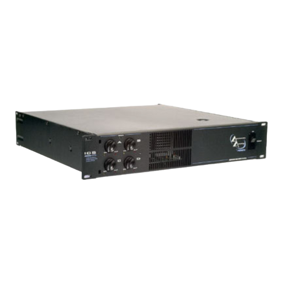
- Página 1 ™ User Manual 4200 4-Channel Power Amplifier...
- Página 2 être reparée par l’utilisateur. Confiez I’entretien et la réparation de l’appareil à un réparateur Peavey agréé. A A V V I I S S : : Dans le but de reduire les risques d'incendie ou de decharge electrique, cet appareil ne doit pas etre expose a la pluie ou a l'humidite et aucun objet rempli de liquide, tel qu'un vase, ne doit etre pose sur celui-ci.
- Página 3 I I M M P P O O R R T T A A N N T T S S A A F F E E T T Y Y I I N N S S T T R R U U C C T T I I O O N N S S W W A A R R N N I I N N G G : : When using electrical products, basic cautions should always be followed, including the following: Read these instructions.
- Página 4 Be sure to save the carton and all packing materials. Should you ever need to ship the unit back to Peavey Electronics, one of its offices, service centers, or the supplier, use only the original factory packing. If the shipping carton is unavailable, contact Peavey to obtain a replacement.
- Página 5 O O p p e e r r a a t t i i n n g g P P r r e e c c a a u u t t i i o o n n s s Make sure the mains voltage is correct and is the same as that printed on the rear of the amplifier.
- Página 6 ( ( 1 1 ) ) P P o o w w e e r r I I n n d d i i c c a a t t o o r r F F r r o o n n t t P P a a n n e e l l The green LED indicates AC power is supplied to the unit‚...
- Página 7 MODULE 2 MODULE 1 R R e e a a r r P P a a n n e e l l ( ( 7 7 ) ) A A C C M M a a i i n n s s P P o o w w e e r r R R e e c c e e p p t t a a c c l l e e This is a standard IEC power connector.
- Página 8 I I n n p p u u t t C C o o n n n n e e c c t t i i o o n n s s I I n n p p u u t t s s The Euro-style connectors are wired as: Pin 1 is positive;...
- Página 9 The output of each module may be assigned to any channel and in any combination of channels. To assign the output of Module 1 to an amplifier channel(s)‚ simply slide the appropriate switch in the upper bank of switches to the ON position (right). Likewise‚ to assign the output of Module 2 to an amplifier channel(s)‚...
- Página 10 The inputs are configurable for three modes of operation and the outputs for two modes of operation. M M O O D D E E C C O O N N F F I I G G U U R R A A T T I I O O N N S S I I n n p p u u t t M M o o d d e e s s The channel inputs can be connected in three different ways to achieve the following modes of operation.
- Página 11 B B r r i i d d g g e e d d M M o o d d e e A pair of amplifiers may be bridged together to make a single output with a power rating equal to the sum of both channel power ratings at twice the load rating of a single channel.
- Página 12 O O u u t t p p u u t t M M o o d d e e s s Each channel of the ICS ™ 4200 can drive conventional low-impedance loudspeaker loads (≥4 Ohms) or a 70 Volt constant-voltage audio distribution system directly. The setting of the output selector switches determines the mode for each pair of outputs.
- Página 13 Example of a 70 Volt constant-voltage distribution system...
- Página 14 Use of a 70 Volt matching transformer is possible with a 140 Volt system by connecting the tap that is rated for 1/4 power or less of desired 70 Volt tap. For example‚ a ceiling loudspeaker with a 70 Volt input tapped for 20 Watts is to be used with a 140 Volt constant-voltage system.
- Página 15 CH A LEVEL CH A INPUT SIGNAL 60Hz AMP A MODULE 1 ASSIGN CH A/B OUTPUT CH B LEVEL CH B INPUT SIGNAL 60Hz AMP B 70V Power Supply Low Z Power Supply MODULE 1 MODULE 2 ASSIGN CH C LEVEL CH C INPUT SIGNAL 60Hz...
-
Página 16: Input Sensitivity
™ 4200 SPECIFICATIONS S S P P E E C C I I F F I I C C A A T T I I O O N N L L O O W W Z Z M M O O D D E E 7 7 0 0 V V O O L L T T M M O O D D E E Rated Power (all channels driven) - Página 17 Current Consumption (Multiply current by 0.5 for 230 V units) Rated power 15.4 A (4 Ohms) 13.2 A 9.9 A (8 Ohms) 1/3 power 9.9 A (4 Ohms) 8.6 A 6.3 A (8 Ohms) 1/8 power 6.6 A (4 Ohms) 5.8 A 4.2 A (8 Ohms) Idle...
- Página 18 Si alguna vez necesitas enviar la unidad a Peavey Electronics, o una de sus oficinas, centros de servicio, o al distribuidor, usa sólo el empaque original de fábrica. Si la caja ya no está disponible, contacta a Peavey para hacerte llegar una.
- Página 19 P P r r e e c c a a u u c c i i o o n n e e s s d d e e O O p p e e r r a a c c i i ó ó n n Hay que asegurarse que el voltaje utilizado es el mismo impreso en la parte trasera del amplificador.
- Página 20 ( ( 1 1 ) ) I I n n d d i i c c a a d d o o r r d d e e C C o o r r r r i i e e n n t t e e P P a a n n e e l l F F r r o o n n t t a a l l El LED verde indica que la unidad está...
- Página 21 Módulo 2 Módulo 1 P P a a n n e e l l T T r r a a s s e e r r o o ( ( 7 7 ) ) R R e e c c e e p p t t á á c c u u l l o o d d e e C C a a b b l l e e d d e e C C o o r r r r i i e e n n t t e e Este es para un conectador estándar IEC.
- Página 22 C C o o n n e e x x i i o o n n e e s s d d e e E E n n t t r r a a d d a a E E n n t t r r a a d d a a Los conectores tipo Euro están cableados de la siguiente manera: Aguja 1 es positiva, Aguja 2 es negativa y Aguja 3 es la tierra.
- Página 23 La salida de cada módulo puede ser asignada a cualquier canal y a cualquier combinación de canales. Para asignar la salida del Modulo 1 a un canal(es) del amplificador, simplemente mueve el interruptor apropiado en los interruptores superiores a la posición ON (encendido). Así mismo, para asignar la salida del módulo 2 a un canal(es) del amplificador, mueve el interruptor correspondiente en los interruptores inferiores a la posición de encendido (ON).
- Página 24 Las entradas son configurables para tres modos de operación y las salidas para dos modos de M M o o d d o o s s D D e e operación. C C o o n n f f i i g g u u r r a a c c i i ó ó n n M M o o d d o o s s d d e e E E n n t t r r a a d d a a Las entradas de los canales pueden ser conectadas en tres formas diferentes para alcanzar los siguientes modos de operación.
- Página 25 M M o o d d o o P P u u e e n n t t e e Se pueden ‘puentear’ un par de amplificadores para hacer una sola salida con una potencia de salida igual a la suma de ambos amplificadores y la carga de un solo canal. En otras palabras, puentear dos amplificadores de 200 Watts a 4 Ohmios producirá...
- Página 26 M M o o d d o o s s d d e e S S a a l l i i d d a a ™ Cada Canal del ICS 4200 puede alimentar cargas a parlantes convencionales de baja impedancia (≥4 Ohmios) o un sistema de distribución constante de voltaje constante de 70 Voltios.
- Página 27 Example of a 70 Volt constant-voltage distribution system...
- Página 28 El uso de un transformador igualador de 70 Voltios es posible con un sistema de 140 Voltios conectando la parte que ha sido ajustada para 1/4 de poder o menos de la parte de 70 Voltios. Por ejemplo, Se debe usar un sistema de voltaje constante de 140 Voltios para un parlante de techo con una entrada de 70 Voltios para 20 Watts.
-
Página 29: Especificaciones
™ 4200 ESPECIFICACIONES E E S S P P E E C C I I F F I I C C A A C C I I O O N N E E S S L L O O W W Z Z M M O O D D E E 7 7 0 0 V V O O L L T T M M O O D D E E Rated Power (all channels driven) - Página 30 Current Consumption (Multiply current by 0.5 for 230 V units) Rated power 15.4 A (4 Ohms) 13.2 A 9.9 A (8 Ohms) 1/3 power 9.9 A (4 Ohms) 8.6 A 6.3 A (8 Ohms) 1/8 power 6.6 A (4 Ohms) 5.8 A 4.2 A (8 Ohms) Idle...
- Página 31 4200 ist eine Vierkanal-Endstufe, die für jahrelangen zuverlässigen und störungsfreien Einsatz unter harten Bedingungen entwickelt wurde. Dieser Verstärker zeichnet sich durch die überragende Schallleistung und die einzigartige Zuverlässigkeit aus, für die Peavey bekannt ist, und ist dennoch überraschend kompakt. Fortschrittliche Technologie und umfassende Schutzschaltungen ermöglichen einen effizienteren Betrieb auch bei problematischen Lasten und Energiebedingungen.
- Página 32 können. Werden Racks mit verschlossenen Rückseiten verwendet, muss eine (1) Standard-Rackhöhe für je drei montierte Verstärker offen gelassen werden. Wird das Gerät nicht im Rack montiert, muss auf allen Seiten ein Abstand von 15 cm belassen werden. S S i i c c h h e e r r h h e e i i t t s s h h i i n n w w e e i i s s e e f f ü ü r r d d e e n n B B e e t t r r i i e e b b Achten Sie darauf, dass die Netzspannung korrekt ist und mit den Angaben auf der Rückseite des Verstärkers übereinstimmt.
- Página 33 ( ( 1 1 ) ) ) ) P P o o w w e e r r - - A A n n z z e e i i g g e e V V e e r r t t i i e e f f t t e e s s Die grüne LED leuchtet auf, wenn das Gerät eingeschaltet ist und mit Wechselstrom versorgt wird V V o o r r d d e e r r s s e e i i t t e e und störungsfrei arbeitet.
- Página 34 MODULE 2 MODULE 1 R R e e a a r r P P a a n n e e l l ( ( 7 7 ) ) W W e e c c h h s s e e l l s s t t r r o o m m - - N N e e t t z z s s t t e e c c k k d d o o s s e e Hierbei handelt es sich um einen genormten IEC-Netzstecker.
- Página 35 A A c c h h t t u u n n g g : : M M M M A A ™ ™ - - P P l l u u g g - - i i n n - - M M o o d d u u l l e e d d ü ü r r f f e e n n n n i i c c h h t t e e i i n n g g e e s s t t e e c c k k t t o o d d e e r r h h e e r r a a u u s s g g e e z z o o g g e e n n w w e e r r d d e e n n , , s s o o l l a a n n g g e e d d e e r r V V e e r r s s t t ä...
- Página 36 D D I I P P S S w w i i t t c c h h S S e e t t t t i i n n g g s s E E i i n n g g a a n n g g s s e e n n e e r r i i g g i i e e Der Ausgang jedes Moduls kann jedem Kanal bzw.
- Página 37 Die Eingänge können für drei Betriebsmodi, die Ausgänge für zwei Betriebsmodi konfiguriert werden. M M O O D D U U S S - - K K O O N N F F I I G G U U R R A A T T I I O O N N E E N N E E i i n n g g a a n n g g s s m m o o d d i i Es gibt drei Möglichkeiten, um die Kanaleingänge anzuschließen und so die folgenden Betriebsarten auszuwählen.
- Página 38 B B r r i i d d g g e e d d - - M M o o d d u u s s Ein Verstärkerpaar kann gebrückt werden, um einen einzigen Ausgang mit einer Nennleistung zu erhalten, die der Summe beider Kanal-Nennleistungen bei zweifacher Nennlast eines einzelnen Kanals entspricht.
- Página 39 Überprüfen Sie alle Anschlüsse zweifach, und stellen Sie sicher, dass keine freiliegenden Kabel oder Stecker vorhanden sind, bevor Sie den Verstärker einschalten. Achten Sie bei jedem Einschalten des Verstärkers darauf, dass Kabel oder Drähte unversehrt sind und dass alle Kabel fest und korrekt angeschlossen sind. 6.
- Página 40 Example of a 70 Volt constant-voltage distribution system...
- Página 41 Bei einem 140-Volt-System kann ein 70-Volt-Anpassungstrafo verwendet werden, indem die Abgriffstelle angeschlossen wird, die für höchstens 1/4 der Leistung der gewünschten 70-Volt- Abgriffstelle ausgelegt ist. Für ein 140-Volt-System mit konstanter Spannung muss z.B. ein Deckenlautsprecher mit einem 70-Volt-Eingang mit einer 20-Watt-Abgriffstelle verwendet werden. Das 140-Volt-System muss an die 5-Watt-Abgriffstelle angeschlossen werden, damit der Lautsprecher 20 Watt liefert.
- Página 42 Inspectez votre unité durant son déballage. Si vous constatez le moindre problème, notifiez-le immédiatement auprès de votre revendeur. Assurez-vous de garder les emballages d’origine, si jamais vous deviez renvoyer votre unité chez Peavey Electronics, l’un de ses centres techniques ou votre revendeur.
- Página 43 P P r r é é c c a a u u t t i i o o n n s s d d ’ ’ E E m m p p l l o o i i Assurez-vous d’alimenter correctement votre unité – réfèrez-vous aux inscriptions sur le panneau arrière pour les besoins électriques.
- Página 44 ( ( 1 1 ) ) L L E E D D d d ’ ’ A A l l i i m m e e n n t t a a t t i i o o n n P P A A N N N N E E A A U U A A V V A A N N T T Cette LED verte indique en s’illuminant que votre unité...
- Página 45 MODULE 2 MODULE 1 P P A A N N N N E E A A U U A A R R R R I I E E R R E E ( ( 7 7 ) ) C C o o n n n n e e c c t t e e u u r r d d ’ ’ A A l l i i m m e e n n t t a a t t i i o o n n Un connecteur d’alimentation IEC est situé...
- Página 46 C C o o n n n n e e c c t t e e u u r r s s d d ’ ’ E E n n t t r r é é e e d d ’ ’ E E n n t t r r é é e e Les connecteurs du type EURO sont connectés de la facon suivante: Pin 1 est positive, Pin 2 est négative et Pin 3 est la masse.
- Página 47 La sortie de chaque module peut être assignée à tout canal ou toute combinaison de canaux. Pour assigner la sortie du module au canal 1, il vous suffit de positionner l’interrupteur correspondant sur ON. Quand vous effectuez ces sélections, assurez-vous que les niveaux de gains et de volumes de votre unité soient en position minimum, ou que votre unité...
- Página 48 Les entrés sont configurables selon 3 modes, et les sorties selon 2 modes. C C O O N N F F I I G G U U R R A A T T I I O O N N S S D D E E M M O O D D E E M M o o d d e e s s d d ’...
- Página 49 M M o o d d e e P P o o n n t t ( ( B B r r i i d d g g e e ) ) Une paire d’étage de puissance peuvent être reliée pour se comporter comme un étage unique, donnant une puissance de sortie égale à...
- Página 50 M M o o d d e e s s d d e e S S o o r r t t i i e e s s Chaque canal de votre ICS™ 4200 peut amplifier un système d’enceintes de basse-impédance (≥4 Ohms) ou un système à...
- Página 51 Example of a 70 Volt constant-voltage distribution system...
- Página 52 L’utilisation de transformateurs d’enceintes prévus pour le standard 70V est possible avec un système 140V. Il vous suffit de positionner le sélecteur de puissance au quart de sa valeur sous 70V. Par exemple, une enceinte munie d’un transformateur 70V en position 20 Watts, pourra recevoir un signal d’un système 140V s’il est mis en position 5 Watts.
- Página 53 N N O O T T E E S S : :...
- Página 54 N N O O T T E E S S : :...
- Página 55 H H o o w w T T o o G G e e t t W W a a r r r r a a n n t t y y S S e e r r v v i i c c e e ( ( 1 1 ) ) Take the defective item and your sales receipt or other proof of date of purchase to your Authorized Peavey Dealer or Authorized Peavey Service Center.
- Página 56 80303117 Peavey Electronics Corporation • 711 A Street • Meridian, MS 39301 601-483-5376 • Fax 601-486-1678 • http://aa.peavey.com ©2003 Printed in the U.S.A 9/03...