Tabla de contenido
Publicidad
Idiomas disponibles
Idiomas disponibles
Enlaces rápidos
USA
3833 SALA Way
Red Wing, MN 55066-5005
Toll Free: 800-328-6146
Phone: (651) 388-8282
www.capitalsafety.com
User InstrUctIon ManUal eMbedded concrete anchorage connector
This manual is intended to meet the Manufacturer's Instructions as required by ANSI-Z359.1 and should be used as
part of an employee training program as required by OSHA.
WarnIng: This product is part of a personal fall arrest or restraint system. These instructions must be provided to
the user of this equipment. The user must read and understand these instructions before using this equipment. Users
must follow the manufacturer's instructions for each component of the system. Manufacturer's instructions must be
followed for proper use and maintenance of this equipment. Alterations or misuse of this product, or failure to follow
instructions, may result in serious injury or death.
IMPortant: If you have questions on the use, care, or suitability of this equipment for your application, contact DBI-SALA.
IMPortant: It is the responsibility of the sellor to ensure that these instructions are in the language of the country it is to be sold.
1.0
aPPlIcatIons
1.1
PURPOSE: The embedded concrete anchorage connector is designed as a temporary anchorage connector for a personal
fall arrest or restraint system. The D-ring and Web Connecting Single Loop anchorage connectors are designed for single use
and the D-ring Double Loop anchorage connector is designed to be reused once after initial installation. See Figure 1. Do not
hang, lift, or support tools or equipment from this equipment. When the anchorage connector is used as a component of a
personal fall arrest system (PFAS), it typically includes a full body harness and a connecting subsystem (energy absorbing
lanyard). Maximum permissible free fall is 6 ft. (1.8 m) (ANSI Z359.1) or 4 m (EN355). When the anchorage connector
is used as a component of a restraint system, it must be rigged to prevent the user from reaching a fall hazard. Restraint
systems typically include a full body harness and a lanyard or restraint line. No vertical free fall is permitted.
1.2
LIMITATIONS: Consider the following limitations before using this product: This anchorage connector is designed for use
by persons with a combined weight (clothing, tools, etc.) of no more than 310 lbs. (141 kg). No more than one personal
protective system may be connected at one time. Restraint systems must be rigged so that no vertical free fall is possible.
Personal fall arrest systems used with this equipment must be rigged to limit the free fall to 6 ft. (1.8 m) (ANSI Z359.1) or
4 m (EN355). See the personal fall arrest system manufacturer's instructions for more information. There must be sufficient
clearance below the user to arrest a fall before the user strikes the ground or other obstruction. See Figure 2. The clearance
required is dependent on the following factors: Elevation of anchorage connector, connecting subsystem length, deceleration
distance, movement of harness attachment element, worker height, and free fall distance. See the personal fall arrest system
manufacturer's instructions for more information. Swing falls occur when the anchorage point is not directly above the point
where a fall occurs. See Figure 3. The force of striking an object in a swing fall may cause serious injury or death. Minimize
swing falls by working as close to the anchorage point as possible. Do not permit a swing fall if injury could occur. Swing falls
will significantly increase the clearance required when a self retracting lifeline or other variable length connecting subsystem
is used. Use of this equipment in areas with environmental hazards may require additional precautions to prevent injury to
the user or damage to the equipment. Hazards may include, but are not limited to; heat, chemicals, corrosive environments,
high voltage power lines, gases, moving machinery, and sharp edges. Contact DBI-SALA if you have questions about using this
equipment where environmental hazards exist. This equipment must be installed and used by persons trained in its correct
application and use. See section 4.0.
1.3
APPLICABLE STANDARDS: Refer to national standards, including ANSI Z359.1, local, state, and federal and EU standard EN795 Class A
requirements for more information on personal fall arrest systems and associated components.
2.0
sYsteM reQUIreMents
2.1
COMPATIBILITY OF COMPONENTS: DBI-SALA equipment is designed for use with DBI-SALA approved components and subsystems only.
Substitutions or replacements made with non-approved components or subsystems may jeopardize compatibility of equipment and may effect the
safety and reliability of the complete system.
2.2
COMPATIBILITY OF CONNECTORS: Connectors are considered to be compatible with connecting elements when they have been designed
to work together in such a way that their sizes and shapes do not cause their gate mechanisms to inadvertently open regardless of how they
become oriented. If the connecting element that a snap hook or carabiner attaches to is undersized or irregular in shape, a situation could occur
where the connecting element applies a force to the gate of the snap hook or carabiner. This force may cause the gate (of either a self-locking
or a non-locking snap hook) to open, allowing the snap hook or carabiner to disengage from the connecting point. Contact DBI-SALA if you have
any questions about compatibility. Connectors (hooks, carabiners, and D-rings) must be capable of supporting at least 5,000 lbs. (22.2 kN). Connectors must be
compatible with the anchorage or other system components. Do not use equipment that is not compatible. Non-compatible connectors may unintentionally disengage.
Connectors must be compatible in size, shape, and strength. Self-locking snap hooks and carabiners are required by ANSI Z359.1 and OSHA. In Europe connectors
must conform to EN362.
2.3
MAKING CONNECTIONS: Use only self-locking snap hooks and carabiners with this equipment. Use only connectors
that are suitable to each application. Ensure all connections are compatible in size, shape, and strength. Do not use
equipment that is not compatible. Ensure all connectors are fully closed and locked. DBI-SALA connectors (snap hooks
and carabiners) are designed to be used only as specified in each product's user instructions. See Figure 4. DBI-SALA
snap hooks and carabiners should not be connected:
A. To a D-ring to which another connector is attached.
B. In a manner that would result in a load on the gate.
note: Large throat opening snap hooks should not be connected to standard size D-rings or similar objects which will result
in a load on the gate if the hook or D-ring twists or rotates. Large throat snap hooks are designed for use on fixed structural
elements such as rebar or cross members that are not shaped in a way that can capture the gate of the hook.
C. In a false engagement, where features that protrude from the snap hook or carabiner catch on the anchor, and
without visual confirmation seems to be fully engaged to the anchor point.
D. To each other.
E. Directly to webbing or rope lanyard or tie-back (unless the manufacturer's instructions for both the lanyard and connector specifically allow such a connection).
F. To any object which is shaped or dimensioned such that the snap hook or carabiner will not close and lock, or that roll-out could occur.
2.4
PERSONAL FALL ARREST SYSTEM: Personal fall arrest systems used with this equipment must meet applicable state, federal, OSHA, and ANSI requirements. A full
body harness must be worn when this equipment is used as a component of a personal fall arrest system. As required by OSHA, the personal fall arrest system must
be capable of arresting the user's fall with a maximum arresting force of 1,800 lbs. (8 kN) or in EU 1,350 lbs. (6kN) per EN355, and limit the free fall to 6 ft. (1.8 m),
4 m in EU or less. If the maximum free fall distance must be exceeded, the employer must document, based on test data, that the maximum arresting force will not
be exceeded, and the personal fall arrest system will function properly. In Europe Sala EN355 lanyards are recommended to limit the arresting force to 1350 lb (6kN).
2.5
ANCHORAGE STRUCTURE: This equipment is intended to be installed on structures capable of meeting the anchorage strength requirements specified below.
2.6
ANCHORAGE STRENGTH: The anchorage strength required is dependent on the application. Following are anchorage strength requirements for specific applications:
A. FALL ARREST: The structure to which the anchorage connector is attached must sustain static loads applied in the directions permitted by the fall arrest system
of at least: 3,600 lbs. (16.0 kN) with certification of a qualified person, or 5,000 lbs. (22.2 kN) without certification. See ANSI Z359.1 for certification definition.
When more than one personal fall arrest system is attached to an anchorage, the strengths stated above must be multiplied by the number of personal fall
arrest systems attached to the anchorage.
Canada
Northern Europe
260 Export Boulevard
Manor Park, Runcorn,
Mississauga, Ontario L5S 1Y9
Cheshire WA7 1st
Toll Free: 800-387-7484
Tel: 01928 571324
Phone: (905) 795-9333
Fax: 01928 571325
www.capitalsafety.com
www.capitalsafety.com
EMEA
Le Broc Center, Z.I. 1ère Avenue
06510 Carros Le Broc, Cedex, France
Tel: +(33) (0)4 97 10 00 10
Fax: +(33) (0)4 93 08 79 70
www.capitalsafety.com
2100050, 2100051, 2100052, 2100053, 2100054,
information@capitalsafety.com
2100055, 2100056, 2100057, 2100058, 2100059,
2100060,2100061, 2100062
Instructions for the following
series products:
Embedded Concrete Anchorage Connector
Model Numbers:
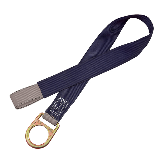
Figure 1 - Embedded Concrete Anchor Connectors
D-RING CONNECTING SINGLE LOOP (ONE USE)
Connecting
Wear Sleeve
Web Loop
D-Ring
Labels
D-RING CONNECTING DOUBLE LOOP (TWO USES)
Connecting
Web Loops
D-Ring
Wear Sleeves
Labels
WEB LOOP CONNECTING SINGLE LOOP (ONE USE)
Connecting
Web Loop
Web Loop
Wear Sleeve
Labels
Figure 2 - Fall Clearance
Maximum:
6 ft. (ANSI) or
4 m (CE)
Figure 3 - Swing Falls
Figure 4 - Inappropriate Connections
GB
Publicidad
Tabla de contenido

Manuales relacionados para DBI SALA 2100050


Resumen de contenidos para DBI SALA 2100050
- Página 1 Phone: (905) 795-9333 Fax: 01928 571325 www.capitalsafety.com www.capitalsafety.com www.capitalsafety.com www.capitalsafety.com 2100050, 2100051, 2100052, 2100053, 2100054, information@capitalsafety.com 2100055, 2100056, 2100057, 2100058, 2100059, 2100060,2100061, 2100062 User InstrUctIon ManUal eMbedded concrete anchorage connector This manual is intended to meet the Manufacturer's Instructions as required by ANSI-Z359.1 and should be used as Figure 1 - Embedded Concrete Anchor Connectors part of an employee training program as required by OSHA.
-
Página 2: Warning Label
FROM OSHA 1926.500 AND 1910.66: Anchorages used for attachment of a personal fall arrest system shall be independent of any anchorage being used to support or suspend platforms, and must support at least 5,000 lbs. (22.2 kN) per user attached; or be designed, installed, and used as part of a complete personal fall arrest system which maintains a safety factor of at least two, and is supervised by a qualified person. -
Página 3: Configuration Du Systeme
Numéros de modèle : Tél. : (651) 388-8282 www.capitalsafety.com www.capitalsafety.com www.capitalsafety.com 2100050, 2100051, 2100052, 2100053, 2100054, www.capitalsafety.com information@capitalsafety.com 2100055, 2100058, 2100059, 2100060, 2100061 Mode d’eMPloI de la FIxatIon d’ancrage PoUr béton Ce manuel est conforme aux instructions du fabricant (norme ANSI-Z359.1) et peut être utilisé dans le cadre d’un programme de formation, tel Figure 1 - Fixations d’ancrage à béton... -
Página 4: Étiquette De Sécurité
D’APRèS LES NORMES 1926.500 ET 1910.66 DE L’OSHA : Les ancrages utilisés pour la fixation d’un dispositif antichute ne doivent pas comporter d’ancrage utilisés pour supporter ou suspendre des plates-formes et doivent supporter au moins 22,2 kN (5 000 livres) par utilisateur attaché ; ou être conçus, installés et utilisés dans le cadre d’un dispositif antichute complet garantissant un facteur de sécurité d’au moins deux et se trouvant sous la supervision d’une personne qualifiée. B. RETENUE : La structure à laquelle une fixation d’ancrage est attachée doit supporter des charges statiques dans les directions permises par le dispositif de retenue d’au moins 13,3 kN (3 000 livres). - Página 5 Fax: +(33) (0)4 93 08 79 70 Modellnummern: www.capitalsafety.com www.capitalsafety.com www.capitalsafety.com www.capitalsafety.com 2100050, 2100051, 2100052, 2100053, 2100054, information@capitalsafety.com 2100055, 2100058, 2100059, 2100060, 2100061 bedIenUngsanleItUng IntegrIerter betonVerankerUngsanschlUss Dieses Handbuch enthält die Anweisungen des Herstellers wie nach ANSI-Z359.1 erforderlich, und soll als Teil der Mitarbeiterschulung wie nach OSHA Abbildung 1 - Integrierte Betonankeranschlüsse (Occupational Safety and Health Association - USA) erforderlich, verwendet werden.
- Página 6 NACH OSHA 1926.500 UND 1910.66: Verankerungen, an denen ein persönliches Fallsicherungssystem angebracht wird, müssen unabhängig von einer Verankerung sein, die dafür verwendet wird, Plattformen zu stützen oder schwebend zu halten, und müssen mindestens 22,2 kN pro befestigtem Benutzer halten; oder als Teil eines kompletten persönlichen Fallsicherungssystems konzipiert, installiert und verwendet werden, das einen Sicherheitsfaktor von mindestens zwei einhält, und von einer qualifizierten Person überwacht wird.
- Página 7 Fax: +(33) (0)4 93 08 79 70 Numeri modello: Tel.: (651) 388-8282 www.capitalsafety.com www.capitalsafety.com www.capitalsafety.com 2100050, 2100051, 2100052, 2100053, 2100054, www.capitalsafety.com information@capitalsafety.com 2100055, 2100058, 2100059, 2100060, 2100061 ManUale d’Uso Per Utente Per Il connettore dI ancoraggIo IncorPorato nel ceMento Figura 1 - Connettori di ancoraggio incorporati nel cemento Il manuale è rivolto a soddisfare le Istruzioni del produttore, come previsto in conformità a ANSI-Z359.1 e deve essere utilizzato nell’ambito di ANELLO A D PER COLLEGAMENTO CIRCUITO SINGOLO (NON RIUTILIZZABILE) un programma di formazione dei dipendenti come previsto da OSHA.
- Página 8 IN CONFORMITÀ ALLA NORMA OSHA 1926.500 E 1910.66: gli ancoraggi utilizzati per il collegamento di un sistema anticaduta personale devono essere indipendenti da qualsiasi ancoraggio utilizzato per sostenere o sospendere piattaforme e deve essere in grado di sostenere almeno 22,2 kN (5.000 libbre) per ogni utente agganciato oppure essere progettate, installate e utilizzate nell’ambito di un sistema anticaduta personale completo che mantiene un fattore di sicurezza di almeno secondo livello e supervisionato da una persona qualificata.
-
Página 9: Limitaciones
Fax: +(33) (0)4 93 08 79 70 Números de modelo: Teléfono: (651) 388-8282 Teléfono: (905) 795-9333 www.capitalsafety.com www.capitalsafety.com 2100050, 2100051, 2100052, 2100053, 2100054, www.capitalsafety.com www.capitalsafety.com information@capitalsafety.com 2100055, 2100058, 2100059, 2100060, 2100061 contIene ManUal de InstrUccIones del UsUarIo conector de anclaje en horMIgón Este manual se ha diseñado según las Instrucciones del fabricante, como lo exige la ANSI-Z359.1, y debe utilizarse como parte del programa Figura 1 - Conectores de Anclaje Empotrados en Hormigón... -
Página 10: Instalación Del Anclaje Empotrado En Hormigón
DE LAS 1926.500 Y 1910.66 DE OSHA: Los anclajes utilizados para la conexión de un sistema de protección personal contra caídas, debe ser independiente de cualquier anclaje que se utilice para sostener o suspender plataformas, y debe soportar al menos 5.000 lbs. (22,2 kN) por usuario; o ser diseñados, instalados, y utilizados como parte de un sistema de protección personal completo contra caídas que mantenga un factor de seguridad de al menos dos, y sea supervisado por una persona calificada. - Página 11 Fax: +(33) (0)4 93 08 79 70 Modellnummer: www.capitalsafety.com www.capitalsafety.com www.capitalsafety.com www.capitalsafety.com 2100050, 2100051, 2100052, 2100053, 2100054, information@capitalsafety.com 2100055, 2100058, 2100059, 2100060, 2100061 anVändarManUal tIll Inbäddad betongFörankrIngsanslUtnIng Denna manual är avsedd att uppfylla tillverkarens instruktioner enligt ANSI-Z359.1 och ska användas som en del i ett Figur 1 - Inbäddade betongförankringsanslutningar utbildningsprogram för anställda enligt krav från OSHA.
- Página 12 FRåN OSHA 1926.500 OCH 1910.66: Förankringar som används för fastsättning av personliga fallstoppsystem ska vara fristående från alla förankringar som används för att stötta eller hänga upp plattformar, och måste stötta minst 22,2 kN per ansluten användare; eller vara utformad för, installerad och använd som en del i ett komplett personligt fallstoppsystem som bibehåller en säkerhetsfaktor på...