Tabla de contenido
Publicidad
Idiomas disponibles
Idiomas disponibles
Enlaces rápidos
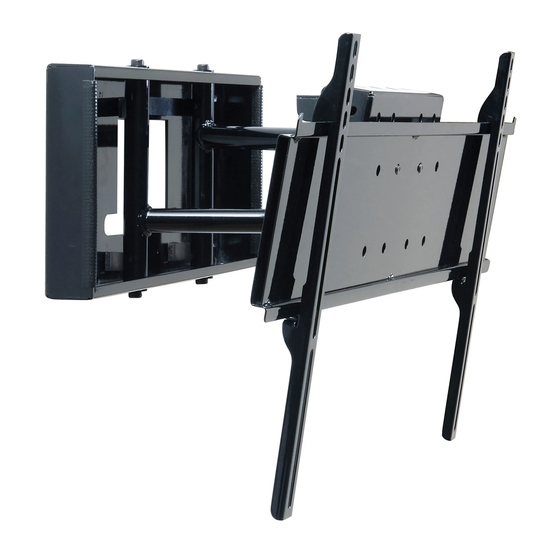
Installation and Assembly:
Pull-out Swivel Wall Mount with Universal Adapter Bracket for
32" - 58" Flat Panel Screens
Models: SP850-UNL, SP850-UNLP, SP850-UNL-S, SP850-UNLP-S
Maximum Load Capacity: 150 lb (68 kg)
3215 W. North Ave. • Melrose Park, IL 60160 • (800) 865-2112 or (708) 865-8870 • Fax: (708) 865-2941 • www.peerlessmounts.com
Publicidad
Capítulos
Tabla de contenido

Manuales relacionados para PEERLESS SmartMount SP850-UNL


Resumen de contenidos para PEERLESS SmartMount SP850-UNL
- Página 1 Installation and Assembly: Pull-out Swivel Wall Mount with Universal Adapter Bracket for 32" - 58" Flat Panel Screens Models: SP850-UNL, SP850-UNLP, SP850-UNL-S, SP850-UNLP-S Maximum Load Capacity: 150 lb (68 kg) 3215 W. North Ave. • Melrose Park, IL 60160 • (800) 865-2112 or (708) 865-8870 • Fax: (708) 865-2941 • www.peerlessmounts.com...
-
Página 2: Tabla De Contenido
Note: Read entire instruction sheet before you start installation and assembly. WARNING • Do not begin to install your Peerless product until you have read and understood the instructions and warnings contained in this Installation Sheet. If you have any questions regarding any of the instructions or warnings, for US customers please call Peerless customer care at 1-800-865-2112, for all international customers, please contact your local distributor. -
Página 3: Parts List
Before you begin, make sure all parts shown are included with your product. Parts may appear slightly different than illustrated. Parts List SP850-UNL SP850-UNLP SP850-UNL-S SP850-UNLP-S Description Qty. Part # Part# Part # Part# A wall mount assembly 201-0385 201-0386 201-0383 201-0384 B locking tab... - Página 4 Security Adapter Bracket Fasteners M4 x 12 mm (6) M5 x 12 mm (4) M6 x 12 mm (4) 510-1079 520-1064 520-1050 M8 x 15 mm (6) 520-1068 M6 x 20 mm (4) M5 x 25 mm (4) 520-9554 520-1122 M8 x 40 mm (4) 520-1152 M6 x 25 mm (4)
-
Página 5: Installation To Wood Stud Wall
Installation to Wood Stud Wall WARNING • Installer must verify that the supporting surface will safely support the combined load of the equipment and all attached hardware and components. • Tighten wood screws so that wall plate is firmly attached, but do not overtighten. Overtightening can damage the screws, greatly reducing their holding power. -
Página 6: Installation To Solid Concrete And Cinder Block
WARNING • When installing Peerless wall mounts on cinder block, verify that you have a minimum of 1-3/8" of actual concrete thickness in the hole to be used for the concrete anchors. Do not drill into mortar joints! Be sure to mount in a solid part of the block, generally 1"... -
Página 7: Mounting Plate
Place installation tab over sliding arms of wall mount assembly (A) to lock them in place. INSTALLATION TAB SLIDING ARM Installing Adapter Plate Thread two M10 x 15 mm screws (K), leaving .25" exposed thread, into top holes on back of adapter plate (EE). Hook adapter plate (EE) to mounting plate and attach using two bottom M10 x 15 mm screws (K) as shown in fig- ures 4.1 and 4.2. -
Página 8: Installing Adapter Brackets
Installing Adapter Brackets WARNING • Tighten screws so adapter brackets are firmly attached. Do not tighten with excessive force. Overtightening can cause stress damage to screws, greatly reducing their holding power and possibly causing screw heads to become detached. Tighten to 40 in. • lb (4.5 N.M.) maximum torque. •... - Página 9 ADAPTER BRACKET (BB OR CC) If you have any questions, please call Peerless customer care at 1-800-865-2112. For Bump-out or Recessed Back Screen Begin with longer length screw, hand thread through multi-washer, adapter bracket and spacer in that order into screen as shown below.
-
Página 10: Mounting And Removing Flat Panel Screen
WARNING • Always use an assistant or mechanical lifting equipment to safely lift and position the plasma television. Mounting and Removing Flat Panel Screen Hook adapter brackets (FF or GG) onto adapter plate (EE), then slowly swing screen in as shown. Turn screws clockwise at least six times to prevent screen from being removed as shown in detail 1. -
Página 11: Back View
Note: Screen not shown for clarity. CABLE MOUNTS SLIDING ARM 11 of 22 ISSUED: 4-03-07 SHEET #: 202-9177-5 02-15-10 © 2008, Peerless Industries, Inc. All rights reserved. All other brand and product names are trademarks or registered trademarks of their respective owners. -
Página 12: Instalación Y Ensamblaje
Instalación y ensamblaje: Unidad de soporte giratorio plegadizo de pared con soporte adaptador para pantallas planas de 32" a 58" Modelos: SP850-UNL, SP850-UNLP, SP850-UNL-S, SP850-UNLP-S Capacidad de carga máxima: 150 lb (68 kg) 3215 W. North Ave. • Melrose Park, IL 60160 • (800) 865-2112 or (708) 865-8870 • Fax: (708) 865-2941 • www.peerlessmounts.com... -
Página 13: Construcción De La Pared
Hoja de Instalación. Si tiene alguna pregunta acerca de cualquiera de las instrucciones o las ad- vertencias, por favor, llame a Servicio al Cliente de Peerless al 1-800-865-2112 si está en EE. UU. Si es un cliente internacional, por favor, comuníquese con su distribuidor local. -
Página 14: Lista De Piezas
Español Antes de comenzar, asegúrese de que su producto contiene todas las piezas que se muestran. Las piezas pueden verse un poco distintas a la ilustración. Lista de piezas SP850-UNL SP850-UNLP SP850-UNL-S SP850-UNLP-S Descriptión Cant. N.o de pieza N.o de pieza N.o de pieza N.o de pieza A Unidad del soporte de pared... -
Página 15: Sujetadores Aseguradores Para Los Soportes Adaptadores
Español Sujetadores aseguradores para los soportes adaptadores M4 x 12 mm (6) M5 x 12 mm (4) M6 x 12 mm (4) 510-1079 520-1064 520-1050 M8 x 15 mm (6) 520-1068 M6 x 20 mm (4) M5 x 25 mm (4) 520-9554 520-1122 M8 x 40 mm (4) -
Página 16: Instalación En Una Pared Con Montantes De Madera
Español Instalación en una pared con montantes de madera ADVERTENCIA • El instalador tiene que asegurarse de que la superficie de apoyo sostendrá, con seguridad, la carga combinada del equipo y todos los fijadores y componentes. • Apriete los tornillos de madera de manera que la placa de pared se fije firmemente, pero no en exceso. Apretarlos en exceso puede dañar los tornillos y puede disminuir significativamente su fuerza de fijación. -
Página 17: Instalación En Una Pared De Concreto Macizo O De Bloques De Hormigón De Escorias
ADVERTENCIA • Cuando vaya a instalar soportes de pared de Peerless en bloques de hormigón de escorias, asegúrese de que cuente con una capa de concreto de un grosor mínimo de 1-3/8" en el agujero, que pueda usar para los anclajes para concreto. -
Página 18: Instalación De La Placa Adaptadora
Español Coloque la lengüeta de instalación sobre los brazos deslizables de la unidad del soporte de pared (A) para fijarlos en su lugar. LENGÜETA DE INSTALACIÓN BRAZO DESLIZABLE Instalación de la placa adaptadora Enrosque dos tornillos de M10 x 15 mm (K), dejando .25" de la rosca expuesta, en los agujeros superiores de la parte trasera de la placa de pared (EE). - Página 19 Español Instalación de la placa adaptadora ADVERTENCIA • Apriete los tornillos de tal modo que los soportes adaptadores queden firmemente sujetos. No apriete aplicando demasiada fuerza. E l apriete excesivo puede causar daño por esfuerzo a los tornillos, reduciendo enormemente su fuerza de fijación y causando el posible desprendimiento de sus cabezas.
- Página 20 ADAPTADOR (BB o CC) Si tiene alguna pregunta, por favor, llame a servicio al cliente de Peerless al 1-800-865-2112. Instalación de un televisor que tiene la parte posterior abultada o empotrada Comience con uno de los tornillos más largos, enrósquelo, con la mano, a través de la arandela, el soporte adaptador y el espaciador, en ese orden, a la parte posterior de la pantalla, como se muestra abajo.
-
Página 21: Montaje Y Desmontaje De La Pantalla Plana
Español ADVERTENCIA • Siempre cuente con un asistente o con un equipo mecánico de izar para levantar y colocar los televisores de pan- talla plana con más seguridad. Montaje y desmontaje de la pantalla plana Enganche los soportes adaptadores (FF o GG) al soporte adaptador (EE) y, luego, gire la pantalla lentamente hacia dentro, como se muestra. -
Página 22: Vista Posterior
SOPORTES PARA CABLES BRAZO DESLIZABLE 22 de 22 PUBLICADO: 4-03-07 HOJA #: 202-9177-5 02-15-10 © 2008, Peerless Industries, Inc. All rights reserved. All other brand and product names are trademarks or registered trademarks of their respective owners.