Tabla de contenido
Publicidad
Idiomas disponibles
Idiomas disponibles
Enlaces rápidos
8026121//2021-02-23
SICK AG
Erwin-Sick-Straße 1
D-79183 Waldkirch
www.sick.com
RMS1000 (Model RMS-A)
Q U I C K S T A R T
1
About this document
The purpose of this Quickstart is to allow you to commission the product quickly
and easily.
Supplementary and other relevant documents:
Safety notes, printed copy included
•
•
RMS1000 operating instructions, available for download
•
RMS1000 "Regulatory Notes" technical information, printed copy included
and available for download
•
RMS1000 Telegram Listing, available for download
Documents available for download and additional information, such as applica‐
tion examples and associated software, can be found on the SICK product page
on the Internet at:
www.sick.com/RMS1000
All rights reserved. Subject to change without notice.
2
Safety information
2.1 Intended use
The RMS1000 radar sensor is used for area monitoring. Within a defined detec‐
tion area, the sensor detects static and moving objects, and triggers a switching
signal upon detection of a corresponding object.
Distance zones can be defined and these zones can be assigned various func‐
tions.
The distance and speed of the objects within the detection area are determined
and provided via the data telegram.
All object data can be provided via Ethernet. The ability to provide it via
CAN J1939 is under development.
The device is operated via the SOPASair software from SICK AG.
NOTE
The radar sensor is approved for operation in countries listed in the
RMS1000 "Regulatory Notes" technical information (no. 8026123). This
document is included with the device. The operation of the device in other
countries can interfere with protected frequency ranges.
•
Only use the device in countries in which it has been approved.
•
When reselling the device, inform the buyer about the regional approval
restrictions.
SICK AG assumes no liability for losses or damage arising from the use of the
product, either directly or indirectly. This applies in particular to use of the product
that does not conform to its intended purpose and is not described in this docu‐
mentation.
3
Product description
3.1 Scope of delivery
The delivery of the device includes the following components:
No. of
Component
units
1
Device in the version ordered
1
SOPASair configuration soft‐
ware
1
Set of protective caps for elec‐
trical connections
1
Printed RMS1000 "Regulatory
Notes" technical information
(no. 8026123)
1
Printed safety notes, multilin‐
gual
8026121//2021-02-23/en, de, es, pt, ko
Remarks
Without connecting cables and brackets
integrated into the device, access via web browser
Included or possibly attached to the device
Informs about the countries for which an approval
exists. Names country-specific aspects which are
to be taken into account during operation of the
device.
Brief information and general safety notes
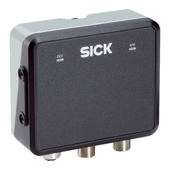
3.2 Connections and LEDs
1
e n
1
3
4
Figure 1: Connections and LEDs
LED 1 Device (Dev)
1
LED 2 Application (App)
2
Connection Ethernet
3
Connection CAN I/O
4
Connection Power
5
Connections
For details,
see Connection diagram, page
LEDs
The LEDs indicate the following status information.
Device status
LED 1 Device (Dev)
LED 2 Application (App)
Device off
Initialization
phase
Parameteriza‐
tion
Field clear
2
Object detec‐
tion
2
No field created
Error (can be
remedied by the
customer)
Serious error
(contact SICK
Service)
Standby/save
electricity
Firmware update
Colors:
1
•
Red
•
Yellow
•
Green
Patterns:
•
Off
•
Permanently lit
•
Flashing slowly (1 Hz)
•
Flashing quickly (8 Hz)
The LEDs indicate the status of the detection or evaluation in a field and not the status
2
of the digital output. If the result of the field evaluation is inverted before being placed on
the digital output, this has no effect on the LEDs.
4
Mounting
4.1 Mounting instructions
•
Observe the technical data.
•
Protect the sensor from direct sunlight.
•
To prevent condensation, avoid exposing the device to rapid changes in
temperature.
•
The mounting site has to be designed for the weight of the device.
It should be mounted so that it is exposed to as little shock and vibration
•
as possible. Optional mounting accessories are available,
page
2.
2
2
5
2.
Description
1
1
Off
Off
Permanently red
Permanently red
Permanently red
Permanently red
Permanently green
Permanently green
Permanently green
Permanently yellow
Permanently green
Off
Slowly flashing red
Slowly flashing red
Synchronous
Quickly flashing red
Quickly flashing red
Synchronous
Permanently yellow
Permanently red
Slowly flashing red
Slowly flashing green
Asynchronous
RMS1000 (Model RMS-A) | SICK
see Accessories,
1
Publicidad
Tabla de contenido

Manuales relacionados para SICK RMS-A


Resumen de contenidos para SICK RMS-A
- Página 1 Serious error Quickly flashing red (contact SICK Quickly flashing red SICK AG assumes no liability for losses or damage arising from the use of the Service) Synchronous product, either directly or indirectly. This applies in particular to use of the product that does not conform to its intended purpose and is not described in this docu‐...
-
Página 2: Electrical Installation
Download Telegram Listing RMS1000, zum Download • Zum Download verfügbare Dokumente und weitere Informationen wie z. B. Anwendungsbeispiele und zugehörige Software finden Sie auf der SICK-Produkt‐ seite im Internet unter: www.sick.com/RMS1000 8026121//2021-02-23/en, de, es, pt, ko RMS1000 (Model RMS-A) | SICK... -
Página 3: Lieferumfang
Alle Objektdaten können über Ethernet bereitgestellt werden. Eine Bereitstellung seitig behebbar) Langsam blinkend Rot Synchron über CAN J1939 ist in Vorbereitung. Die Bedienung des Geräts erfolgt über die Software SOPASair der SICK AG. Schwerer Fehler Schnell blinkend Rot (SICK Service Schnell blinkend Rot... - Página 4 CAN J1939. ✓ Das Gerät schaltet sich aus. Die Gerätekonfiguration bleibt erhalten, Mess‐ El manejo del dispositivo se efectúa a través del software SOPASair de SICK AG. werte gehen verloren. Gerät an die Spannungsversorgung anschließen.
-
Página 5: Conexiones Y Led
Tierra de la salida digital. Cuando el resultado de la evaluación del campo se da invertido en la salida digital, no tiene ningún efecto sobre los LED. OUT4 Salida 4 8026121//2021-02-23/en, de, es, pt, ko RMS1000 (Model RMS-A) | SICK... - Página 6 • restrições regionais da licença. 7.1 Características A SICK AG se isenta de qualquer responsabilidade por perdas ou danos ou Principio de medición FMCW perdas resultantes da utilização do produto. Isto é especialmente válido para uma utilização do produto que seja diferente da finalidade prevista e que não Homologación de radio...
-
Página 7: Instalação Elétrica
Tensão de alimentação: +9,5 … +36 V CC • Fixar o dispositivo tão livre de vibrações e oscilações quanto possível. M12, 5pinos Estão disponíveis acessórios de montagem, opcionalmente, ver Acessórios, Entrada 1 Codificado A página Terra 8026121//2021-02-23/en, de, es, pt, ko RMS1000 (Model RMS-A) | SICK... -
Página 8: Ligar O Dispositivo À Eletricidade
• 리십시오. 7.1 Características SICK AG는 제품의 사용으로 인한 직간접적 손실 및 손해에 대해 책임을 지지 않 Princípio de medição FMCW (Frequency-Modulated Continuous Wave - Onda Contínua 습니다. 특히 제품의 본래 목적에서 벗어나며 본 문서에 기술되지 않은 사용 방... - Página 9 용도 또는 환경 조건에 맞는 연결 케이블과 수 커넥터를 사용하십시오. 참조 부 거리 정확도 속품, 페이지 1m² RCS , 20m까지: 0.04m 1m² RCS , 50m까지: 0.1m 공급 전압을 제원에 안내된 사양에 맞게 연결하십시오. 거리 해상도 0.4m 8026121//2021-02-23/en, de, es, pt, ko RMS1000 (Model RMS-A) | SICK...
- Página 10 승용차의 경우 적용되는 전형적인 레이더 단면적 값. 부속품과 필요시 마운팅 정보는 다음 인터넷 페이지에서 확인할 수 있습니 거리에 따른 작동 범위 다. • www.sick.com/RMS1000 거리[m] 수직 11.2 14.0 수평 17.3 34.6 69.3 138.6 207.8 277.1 346.4 8026121//2021-02-23/en, de, es, pt, ko RMS1000 (Model RMS-A) | SICK...
- Página 11 8026121//2021-02-23/en, de, es, pt, ko RMS1000 (Model RMS-A) | SICK...