Tabla de contenido
Publicidad
Idiomas disponibles
Idiomas disponibles
Enlaces rápidos
Sine Wave DC-to-AC Inverter/Chargers
Table of Contents
3. Battery Installation
and Maintenance
Owner's Manual
Models: APS1012SW, APS2012SW
12VDC to 120VAC
2
3
3
3
6
6
6
6
6
6
8
8
8
1111 W. 35th Street, Chicago, IL 60609 USA
www.tripplite.com/support
Copyright © 2011 Tripp Lite. All rights reserved.
7. Service and
1
10
10
10
11
11
12
12
13
Publicidad
Capítulos
Tabla de contenido
Solución de problemas

Manuales relacionados para Tripp-Lite APS1012SW


Resumen de contenidos para Tripp-Lite APS1012SW
-
Página 1: Tabla De Contenido
Owner’s Manual Sine Wave DC-to-AC Inverter/Chargers Models: APS1012SW, APS2012SW 12VDC to 120VAC Table of Contents Important Safety Instructions 4. Inverter/Charger Installation and Operation 1. Overview & Features 4.1 Installation 1.1 Overview 4.2 Installation Diagrams and Charts 1.2 Indicators, Controls and Settings 4.3 Installation and Start-Up... -
Página 2: Important Safety Instructions
Important Safety Instructions SAVE THESE INSTRUCTIONS! This manual contains important instructions and warnings that should be followed during the installation, operation and storage of all Tripp Lite Inverter/Chargers. Location Warnings • Install your Inverter/Charger in a location or compartment that minimizes exposure to heat, dust, direct sunlight and moisture. -
Página 3: Overview & Features
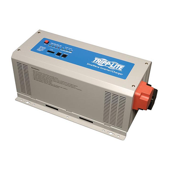
1. Overview and Features 1.1 Overview • Tripp Lite’s Sine Wave Inverter-Charger is a heavy-duty unit generating a pure sine wave from a 12V battery bank. It can supply energy to a wide range of connected equipment; from heaters, air conditioners, refrigerators and vacuum cleaners to computers and peripheral devices. -
Página 4: Power On/Off Button
1. Overview and Features LED and Alarm Indicator LED 1 LED 2 LED 3 LED 4 LED 5 LED 6 LED 7 LED 8 Alarm AC Normal 10.8V~11.5V 11.5 ~ 12.5V 12.5 ~ 13.5V >13.5V Flashing DC Mode 10.2 ~ 11.5V 11.5 ~ 12.5V 12.5 ~ 13.0V >13.0V 1 beep Battery Low 10.2 ~ 11.5V 11.5 ~ 12.5V 12.5 ~ 13.0V >13.0V... - Página 5 1. Overview and Features 1.2.7 Battery Voltage (LED 5-8) LED 5-8 indicate the battery capacity as detailed in the following table: Battery Voltage LED 5 LED 6 LED 7 LED 8 — — — — — — 100% 1.2.8 Voltage Setting (Switch 1-3)* Switch DC-to-AC Transfer Delay (Switch 1) 30 sec (Default)
-
Página 6: Optional Features
These switches control the maximum charging rate in amps. The charge rate has 8 stages. It can be adjusted by setting these switches as shown in the following table: Switch 6 Switch 7 Switch 8 APS1012SW 20A (Default) APS2012SW 30A (Default) Note: The charging rate depends on the battery bank size. Consult the battery manufacturer’s specs for the maximum allowed charge rate (usually 0.3 times the AH rating). - Página 7 3. Battery 3.1.1 Match Battery Amp-Hour Capacity to Your Application Select a battery or system of batteries that will provide your Inverter/Charger with proper DC voltage and an adequate amp- hour capacity to power your application. Even though Tripp Lite Inverter/Chargers are highly-efficient at DC-to-AC inversion, their rated output capacities are limited by the total amp-hour capacity of connected batteries and the support of your vehicle’s alternator if the engine is kept running.
-
Página 8: Monthly Maintenance
3. Battery 3.2 Monthly Maintenance • Check the level of the electrolyte of each Wet-Cell battery cell monthly after the batteries have been charged. It should be about one-half inch above the top of the plates, but not completely full. Note: This is not necessary on maintenance-free batteries. -
Página 9: Inverter/Charger
3. Battery • Connect Fuse: NEC (National Electrical Code) article 551 requires that you connect all of your Inverter/Charger’s positive DC Terminals directly to a UL-listed fuse(s) and fuse block(s) within 18 inches of the battery. The fuse’s rating must equal or exceed the minimum DC fuse rating displayed on the Inverter/Charger’s nameplate. -
Página 10: Installation And Operation
4. Installation and Operation 4.1 Installation 4.1.1 Environment The Inverter/Charger must be installed in a protected location that is isolated from sources of high temperature and moisture. To promote peak performance, battery cables should be kept as short as possible. However, do not install the Inverter/Charger in the same compartment as non-sealed batteries. -
Página 11: Installation And Start-Up
Press the ON/OFF button. The system will start working after a few seconds. If the AC source power fails, the unit will work in Inverter mode. Otherwise, the system will switch to AC Mode and will power the load while charging the battery. 5. Technical Specifications Model APS1012SW APS2012SW Specification Continuous Power... -
Página 12: Troubleshooting
6. Troubleshooting • Your Inverter/Charger requires no maintenance and contains no user-serviceable or user-replaceable parts, but should be kept dry at all times. Periodically check, clean and tighten all cable connections, as necessary, both at the unit and at the battery. -
Página 13: Español
Manual del propietario Convertidores /cargadores de ondas sinusoidales CC a CA Modelos: APS1012SW, APS2012SW 12V CC a 120V CA Índice Instrucciones de seguridad 4. Convertidor/cargador importantes Instalación y funcionamiento 1. Visión de conjunto y 4.1 Instalación características 4.2 Diagramas y gráficos de instalación 22 1.1 Visión de conjunto... -
Página 14: Instrucciones De Seguridad Importantes
Instrucciones de seguridad importantes ¡GUARDE ESTAS INSTRUCCIONES! Este manual contiene instrucciones y advertencias importantes que se deben seguir durante la instalación, el funcionamiento y el almacenaje de todos los convertidores/cargadores Tripp Lite. Advertencias de ubicación • Instale su convertidor/cargador en una ubicación o compartimento que minimice la exposición al calor, polvo, luz solar directa y humedad. -
Página 15: Visión De Conjunto Y Características
1. Visión de conjunto y características 1.1 Visión de conjunto • El convertidor/cargador de ondas sinusoidales de Tripp Lite es una unidad de carga de gran potencia que genera una onda sinusoidal pura a partir de un módulo de baterías de 12V. Puede suministrar energía a gran variedad de equipos conectados: desde radiadores, aparatos de aire acondicionado, refrigeradores y aspiradoras a ordenadores y dispositivos periféricos. -
Página 16: Botón Power On/Off De Encendido/Apagado
1. Visión de conjunto y características LED e indicador de alarmas LED 1 LED 2 LED 3 LED 4 LED 5 LED 6 LED 7 LED 8 Alarma 10.8V~ 11.5 ~ 12.5 ~ CA Normal Off* >13.5V Apagado Flashing*** 11.5V 12.5V 13.5V 10.2 ~... - Página 17 1. Visión de conjunto y características 1.2.7 Voltaje de la batería (LED 5-8) Los LED 5-8 indican la capacidad de la batería como se detalla en la siguiente tabla: Voltaje de la batería LED 5 LED 6 LED 7 LED 8 —...
-
Página 18: Características Opcionales
Interruptor 6 Interruptor 7 Interruptor 8 APS1012SW 20A (Predeterminado) APS2012SW 30A (Predeterminado) Nota 1: el régimen de carga depende del tamaño del módulo de baterías. Consulte las especificaciones del fabricante de la batería para la tasa de carga máxima permisible (normalmente 0.3 veces la especificación AH [Ampers Hours]). -
Página 19: Ajuste De La Capacidad Amperio-Hora De La Batería A Su Aplicación
3. Batería 3.1.1 Ajuste de la capacidad amperio-hora de la batería a su aplicación Seleccione una batería o un sistema de baterías que proporcionen a su convertidor/cargador el voltaje CC y una capacidad amperio-hora adecuada para alimentar su aplicación. Aunque los convertidores/cargadores de Tripp Lite disponen de una alta eficiencia de conversión de CC a CA, sus capacidades de régimen de salida están limitadas por la capacidad amperio-hora total de las baterías conectadas y el respaldo del alternador de su vehículo si el motor está... -
Página 20: Mantenimiento Mensual
3. Batería 3.2 Mantenimiento mensual • Compruebe mensualmente el nivel del electrolito de cada batería de celda húmeda después que las baterías han sido cargadas. Debe estar 13 mm [1/2 media pulgada] aproximadamente sobre el borde superior de las placas, pero no completamente llena. - Página 21 3. Batería • Conectar el fusible: el artículo 551 del NEC (Código Eléctrico Nacional) exige que conecte todos los terminales CC positivos de su convertidor/cargador directamente a un fusible o fusibles homologados por UL y un bloque o bloques de fusibles que sean iguales o excedan el régimen mínimo de fusible CC que se muestra en la placa del convertidor/cargador.
-
Página 22: Instalación Y Funcionamiento
4. Instalación y funcionamiento 4.1 Instalación 4.1.1 Entorno El convertidor/cargador debe estar instalado en una ubicación protegida que esté aislada de fuentes de temperatura y humedad elevadas. Con el fin de fomentar el máximo rendimiento, los cables de la batería deben ser lo más cortos posible. No obstante, no se debe instalar el convertidor/cargador en el mismo compartimento que las baterías no selladas. -
Página 23: Instalación Y Puesta En Marcha
Pulse el botón ON/OFF. El sistema empezará a funcionar en pocos segundos. Si la fuente de energía CA fallase, la unidad funcionará en el modo convertidor. De otro modo, el sistema pasará al modo CA y suministrará potencia mientras carga la batería. 5. Especificaciones técnicas Modelo APS1012SW APS2012SW Especificación Potencia Continua 1000 vatios 2000 vatios Eficiencia Máxima del Inversor... -
Página 24: Solución De Problemas
6. Solución de problemas • Su convertidor/cargador no requiere mantenimiento y no contiene piezas que el usuario deba mantener o sustituir, pero se debe mantener seco en todo momento. Compruebe, limpie y apriete regularmente todas las conexiones de los cables en la medida que sea necesario, tanto en la unidad como en la batería.