
Manuales relacionados para Infiniton CSTT-4550


Resumen de contenidos para Infiniton CSTT-4550
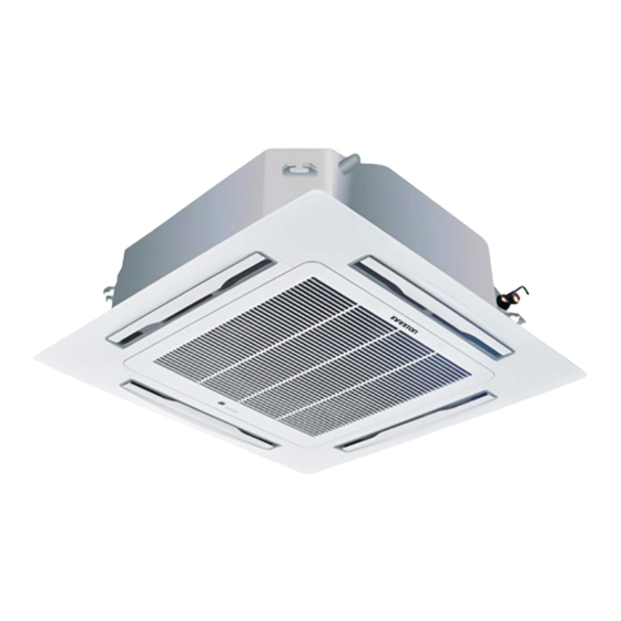
- Página 1 1nF1n1Ton DC Inverter celling-mounted cassette type air conditioner Instruction Manual CSTT-4550 CSTT-6050 CSTT-9400...
- Página 3 1. Original instructions 2. This appliance is intended to be used by expert or trained users in shops,in light industry and on farms,or for commercial use by lay persons. 3. GWP: R410A: 2087.5 or GWP: R407C: 1773.9 . 4. This appliance is not intended for use by persons (including children) with reduced physical,sensory or mental capabilities,or lack of experience and knowledge,unless they have been given supervision or instruction concerning use of the appliance by a person responsible fortheir safety.
-
Página 4: Tabla De Contenido
Content 1.Notice for User Name of air conditioner components Preparation before installation Installation of unit Test run Maintenance and service 7.Symptom analysis and treatment Electric installation Appendix: Unit Packing List... -
Página 5: Safety Notice
1.Notice for User Safety Notice Safety Notice provides the most important safety-related and unit operation key points.Be sure to operate accordingly. Meanings of symbols in documents: Warning It may lead to death, serious injury or major accidents due to mistaken operation. It may lead to safety accident, machine damage or impair the unit operation effect Notice due to improper operation. -
Página 6: General Precautions
1.Notice for User Notice 1. Do not extend the hand or foreign matters into the unit air outlet; otherwise the fan running at high speed may put your safety in hazard. 2. Avoid moisture of unit electric control system; otherwise it may lead to short circuit or damage the machine. - Página 7 1.Notice for User Other Safety Notice 1. The fuse of specified capacity must be used and no iron wire or copper wire must not be used. 2. The unit operation environment shall be far from fire hazard location. In case of fire due to short circuit, immediately turn off the power supply master switch and extinguish the fire with dry powder fire extinguisher.
-
Página 8: Name Of Air Conditioner Components
2.Name of air conditioner components Indoor unit Air supply port of short pipeline Water drainage device (Built-in) 1. It can be used only in case with special demand Drain the water to be removed 2. The connection of short pipe can be from the inside during placed at one side. -
Página 9: Remote Controller
2.Name of air conditioner components Remote controller Temperature addition Mode Increase the setting temperature. Select modes, including automatic, cooling, dehumidification, fan and heating mode. Temperature reduction Decrease the setting temperature. Fan speed + Increase fan speed in one gear. Highest wind speed will swich to the “ON/OFF”... - Página 10 2.Name of air conditioner components Wind direction key: The wind direction is set as winging state in default during first time power on; press this key and it will circulate in sequence of "Swing → Stop → Swing". Wind speed key: The wind speed is set at automatic wind speed in default during first time power on; in dehumidification mode, the speed wind is fixed as low speed and can not be adjusted;...
- Página 11 2.Name of air conditioner components Notices for remote controller: ① Do not place the remote controller near the high temperature heat sources such as electric carpet or heating oven. ② Do not put the remote controller at the position directly exposed to the sunshine. ③...
-
Página 12: Indoor Unit
3.Preparation before installation Notice: The installation of unit must be done by professional staff; the improper installation may lead to water leak, electric shock or fire hazard. Field selection Indoor unit 1) It shall be installed at the place whether the air blown out can quickly spread the entire room and with certain maintenance space. - Página 13 3.Preparation before installation When there are barriers at front side and back side, at the location with barrier and poor air ventilation, to avoid short circuit of outdoor unit inlet and outlet, the heights and widths of barriers shall be within following range.
- Página 14 3.Preparation before installation 3. Mounting at roof or other windy position When the outdoor unit is to be mounted on the roof or place around which there is no building, it is necessary to avoid the strong force directly blowing into the air outlet of outdoor unit. To avoid impairing the heating or cooling effect and failure due of outdoor unit heat exchanger due to inadequate air flow.
-
Página 15: Installation Of Unit
4.Installation of unit Install the indoor unit 1. Installation position If the humidity and temperature on ceiling separately exceed 30℃ and RH80%, please affix the thermal insulation materials on machine. Please use the glass wool or foaming polyethylene with the thickness of more than 10mm. - Página 16 4.Installation of unit 2. Preparation before installation 1) Position relationship among ceiling opening, unit and hoisting bolt Hanging bracket seat Refrigerant pipe Ceiling Hoisting bolt x 4 D ( distance between hoisting bolts) C (indoor unit) B (ceiling opening) Above 20 A (trim plate) Unit: (mm)...
- Página 17 4.Installation of unit 3. Installation A. When there is no installation position on the ceiling ① Attach the hanging bracket seat to the hoisting bolt; be sure to use bolt and nut separately at upper and lower head of the hanging bracket seat to firmly fix the hanging bracket seat; use locating plate 7 to avoid the washer coming-off.
- Página 18 4.Installation of unit 4. Preparation of trim panel B. Install the trim panel ① Do not face the panel downward; do not lean against the wall or onto the protruding object. ② Do not knock or extrude the swinging baffle. (Otherwise it may lead to failure) Take down the air return grating from the trim panel 1.
- Página 19 4.Installation of unit C. Hoisting height of indoor unit Please adjust the hoisting height of indoor unit to make the dimensions of Indoor unit indoor unit under the ceiling as shown in right figure. Panel 10~13 ① When there is gap between indoor unit and panel, the condensation may occur.
- Página 20 4.Installation of unit Install the outdoor fan 1. Installation notice: A. Transport the machine parts in origin package state to installation location. B. Since the outdoor unit weight deflects from center position, take care when lifting the machine parts with sling. C.
- Página 21 4.Installation of unit Note: When the height is more than 5m, set the oil trapping bend and non-return bend according to relative positions of outdoor unit and indoor unit. Non-return bend Non-return bend Gas pipe Gas pipe Indoor unit Oil trapping bend Oil trapping bend Outdoor unit Liquid pipe...
- Página 22 4.Installation of unit Notice: ① When the connection pipe length is more than 5m, it must be evacuated with vacuum pump; after evaporation, it shall be refilled according to requirements of "Adjustment of refrigerant usage amount". ② If the air conditioner is necessary to transfer to the other position, discharge the air with vacuum pump or refrigerant.
- Página 23 4.Installation of unit Notice for the drainage lift pipe: 1.The installation height of drainage lift pipe shall be less than 550mm. 2.The exhaust lift pipe shall be perpendicular to the unit and be no more than 300mm from the unit. Ceiling 1-1.5m Within 300mm...
-
Página 24: Test Run
5.Test run Confirmation before test run After installation of indoor and outdoor units, piping and wiring, , please confirm there is no refrigerant leak, loose of power supply line and signal line, and no mistaken polarity. Note: The compressor will not run in case of mistaken connection of power supply line. Note : Before test run, be sure to take out 4 air wheel damper blocks (A) and fixing tape! Test run... -
Página 25: Cleaning Procedures
6.Maintenance and service Frequently sweep the air filter screen The blocked screen may reduce the air circulation volume and therefore the cooling/heating effect; the excess dirt of screen may lead to failure of air conditioner. Please wash the screen once every two weeks. If not used for long time, please wash the screen before used again., Cleaning procedures: Remove the filter screen;... - Página 26 6.Maintenance and service End of operation season 1.Start the air conditioner and set as air supply mode; after running for 3-4 hours, fully dry the inside of air conditioner; 2.Turn off the air conditioner and cut off the special power supply of air conditioner; 3.Completely clean the filter screen and indoor unit;...
-
Página 27: Symptom Analysis And Treatment
7.Symptom analysis and treatment Failure analysis When the air conditioner can not normally operate, in case of any doubt, please read following contents before communicating the maintenance department so as to save valuable time and energy. Reason Handling method Problems Phenomenon Press "ON/OFF"... -
Página 28: Self-Diagnosis Function
7.Symptom analysis and treatment Self diagnosis function Our company provides considerate service for the customer and install various judgment systems to indicate following abnormalities. Table 1 Indoor unit unit(digital display) When unit is standby after first time power on, running light flash slowly, after operation, all the lights off when the unit is off or standby. - Página 29 7.Symptom analysis and treatment Table 2: Indoor unit (LED display) Error descriptio n Display content Indoor unit waiting for address assignment LED timer and running flash together (reserve) LED timer, running, protection, defrost flash together Communication error between outdoor unit and indoor unit LED timer flash quickly Fan motor stall protection LED timer flash slowly...
- Página 30 7.Symptom analysis and treatment Table 3: Wired controller Display Error description Display Error description Phase protection (reserve) Communication error between outdoor unit and (reserve) indoor unit Indoor room temperature (T1) sensor error (reserve) Outdoor unit current error cannot recover Indoor coil middle temperature (T2) sensor error Display P3 error for 3 times within 60 minutes Indoor coil outlet temperature (T2B) sensor error Outdoor temperature (T4) sensor error...
-
Página 31: Electric Installation
8.Electric installation Notice: 1.The machine unit shall be installed according to national wiring regulations, and also for the use of power supply, assembly of electric leak protection switch; the switch rated working current shall be no less than 1.5-3 times of complete machine rated working current (the complete machine rated working current refers to the attached Instructions for Use and Operation;... - Página 32 8.Electric installation Electric connection of indoor unit: 1.Remove the cover plate of indoor unit electric appliance box. 2.Connect the power supply line and signal line with related terminals ash shown in the figure. 3.Open the wire pressing clip, pass the power supply line and signal line through the valve plate and firmly hold in the pressing clip.
-
Página 33: Outdoor Unit
Annex: Unit Package List Indoor unit paper box 1 set Indoor unit Install the paper board 1piece Attachment package1: 8 hexagon nuts; 8 washer; 1 drainage hose, 2 hose clamps; 5 ribbons, 4 hoisting rods. Note: The details refer to the actual article. 1 group Attachment package 2: 1 Installation and Operation Instruction (including the product after-sales service card), 1 remote... -
Página 34: Síguenos En Nuestras Redes Sociales Y Accede A Contenido Exclusivo
Resumen de Declaración de conformidad INFINITON declara, bajo su responsabilidad, que este aparato cumple con lo dispuesto en la Directiva 99/05/CE del Parlamento Europeo y del Consejo de 9 de Marzo de 1 999, traspuesta a la legislación española mediante el Real Decreto 1 890/2000, de 20 de Noviembre. - Página 36 1nF1n1Ton Aire acondicionado tipo cassette montado en la celda del inversor de CC Manual de instrucciones CSTT-4550 CSTT-6050 CSTT-9400...
-
Página 38: Eliminación Correcta De Este Producto
1. Instrucciones originales 2. Este aparato está destinado a ser utilizado por usuarios expertos o capacitados en tiendas, en la industria ligera y en granjas, o para uso comercial por parte de legos. 3. GWP: R410A: 2087.5 o GWP: R407C: 1773.9. 4. - Página 39 Contenido Aviso para el usuario Nombre de los componentes del aire acondicionado. Preparación antes de la instalación Instalación de la unidad Prueba de funcionamiento Mantenimiento y servicio 7. Análisis de síntomas y tratamiento. 8. Instalación eléctrica Apéndice: Lista de embalaje de la unidad...
-
Página 40: Aviso Para El Usuario
1. Aviso para el usuario Aviso de seguridad El Aviso de seguridad proporciona los puntos clave más importantes relacionados con la seguridad y el funcionamiento de la unidad. Asegúrese de operar en consecuencia. Significados de los símbolos en los documentos: Puede provocar la muerte, lesiones graves o accidentes graves debido a una Peligro operación errónea. -
Página 41: Precauciones Generales
1. Aviso para el usuario Aviso 1. No extienda la mano o materias extrañas en la salida de aire de la unidad; de lo contrario, el ventilador funcionando a alta velocidad puede poner en peligro su seguridad. 2. Evite la humedad del sistema de control eléctrico de la unidad; de lo contrario, puede provocar un cortocircuito o dañar la máquina. -
Página 42: Otro Aviso De Seguridad
1. Aviso para el usuario Otro aviso de seguridad 1. Se debe usar el fusible de la capacidad especificada y no se debe usar alambre de hierro o de cobre. 2. El entorno de operación de la unidad debe estar lejos de la ubicación de peligro de incendio. En caso de incendio debido a cortocircuito, apague inmediatamente el interruptor principal de la fuente de alimentación y apague el fuego con un extintor de polvo seco. -
Página 43: Nombre De Los Componentes Del Aire Acondicionado
2.Nombre de los componentes del aire acondicionado. Unidad interior Puerto de suministro de aire de tubería corta El drenaje del agua dispositivo (incorporado) 1. Puede usarse solo en caso de demanda especial Drene el agua que se 2. La conexión del tubo corto se puede eliminará... -
Página 44: Control Remoto
2.Nombre de los componentes del aire acondicionado. Control remoto Adición de temperatura Modo Aumente la temperatura de ajuste. Seleccione modos, incluidos los modos automático, enfriamiento, deshumidificación, ventilador y calefacción. Reducción de temperatura Disminuya la temperatura de ajuste. Velocidad del ventilador + Aumente la velocidad del ventilador en una marcha. - Página 45 2.Nombre de los componentes del aire acondicionado. Tecla de dirección del viento: la dirección del viento se establece como estado de aleteo en forma predeterminada durante el primer encendido; presione esta tecla y circulará en la secuencia de "Swing → Stop → Swing". Tecla de velocidad del viento: la velocidad del viento se establece en la velocidad del viento automática de forma predeterminada durante el primer encendido;...
-
Página 46: Avisos Para El Control Remoto
2.Nombre de los componentes del aire acondicionado. Avisos para el control remoto: ① Do not place the remote controller near the high temperature heat sources such as electric carpet or heating oven. ② Do not put the remote controller at the position directly exposed to the sunshine. ③... -
Página 47: Preparación Antes De La Instalación
3.Preparación antes de la instalación Aviso: La instalación de la unidad debe ser realizada por personal profesional; La instalación incorrecta puede provocar fugas de agua, descargas eléctricas o peligro de incendio. Selección de campo 1. Unidad interior 1) Se instalará en el lugar si el aire expulsado puede propagarse rápidamente por toda la habitación y con cierto espacio de mantenimiento. -
Página 48: Disposición De Varias Filas
3.Preparación antes de la instalación Cuando hay barreras en la parte frontal y posterior, en el lugar con barrera y poca ventilación, para evitar cortocircuitos en la entrada y salida de la unidad exterior, las alturas y anchuras de las barreras deben estar dentro del rango siguiente. - Página 49 3.Preparación antes de la instalación 3. Montaje en el techo u otra posición ventosa Cuando la unidad exterior se va a montar en el techo o en un lugar alrededor del cual no hay edificio, es necesario evitar la fuerte fuerza que sopla directamente en la salida de aire de la unidad exterior. Para evitar perjudicar el efecto de calentamiento o enfriamiento y la falla debido al intercambiador de calor de la unidad exterior debido al flujo de aire inadecuado.
-
Página 50: Instale La Unidad Interior
4.Instalación de la unidad Instale la unidad interior 1. Posición de instalación Si la humedad y la temperatura en el techo exceden por separado 30 ℃ y RH80%, fije los materiales de aislamiento térmico en la máquina. Utilice lana de vidrio o polietileno espumoso con un espesor de más de 10 mm. -
Página 51: Descripción
4.Instalación de la unidad 2. Preparación antes de la instalación 1) Relación de posición entre la abertura del techo, la unidad y el perno de elevación Colgando asiento de soporte Tubo de refrigerante Techo Perno de elevación x 4 D (distancia entre pernos de elevación) C (unidad interior) B (apertura de techo) Por encima de 20... - Página 52 4.Instalación de la unidad 3. Instalación A. Cuando no hay posición de instalación en el techo ① Fije el asiento del soporte colgante al perno de elevación; asegúrese de usar el perno y la tuerca por separado en la cabeza superior e inferior del asiento del soporte colgante para fijar firmemente el asiento del soporte colgante;...
- Página 53 4.Instalación de la unidad 4. Preparación del panel embellecedor B. Instale el panel de ajuste ① No mire el panel hacia abajo; No se apoye contra la pared o sobre el objeto que sobresale. ② No golpee ni extruya el deflector oscilante. (De lo contrario, puede provocar un fallo) Retire la rejilla de retorno de aire del panel de acabado 1.
-
Página 54: Altura De Elevación De La Unidad Interior
4.Instalación de la unidad C. Altura de elevación de la unidad interior Ajuste la altura de elevación de la unidad interior para hacer las dimensiones de la unidad interior debajo del techo como se muestra en Unidad interior la figura de la derecha. Panel ①... -
Página 55: Instale El Ventilador Exterior
4.Instalación de la unidad Instale el ventilador exterior 1. Aviso de instalación: A. Transporte las piezas de la máquina en el estado del paquete de origen a la ubicación de instalación. B. Dado que el peso de la unidad exterior se desvía de la posición central, tenga cuidado al levantar las piezas de la máquina. -
Página 56: Par De Apriete (Kgfm)
4.Instalación de la unidad Nota: Cuando la altura sea superior a 5 m, configure la curva de retención de aceite y la curva de no retorno de acuerdo con las posiciones relativas de la unidad exterior y la unidad interior. Curva sin retorno Curva sin retorno Tubería de gas... - Página 57 4.Instalación de la unidad Aviso: Cuando la longitud de la tubería de conexión es superior a 5 m, debe evacuarse con una bomba de vacío; después ① de la evaporación, se rellenará de acuerdo con los requisitos del "Ajuste de la cantidad de uso de refrigerante". Si es necesario transferir el aire acondicionado a la otra posición, descargue el aire con una bomba de vacío o ②...
- Página 58 4.Instalación de la unidad Aviso para el tubo de drenaje de elevación: 1. La altura de instalación de la tubería de elevación de drenaje será inferior a 550 mm. 2. El tubo de elevación de escape debe ser perpendicular a la unidad y no debe estar a más de 300 mm de la unidad.
-
Página 59: Confirmación Antes De La Prueba De Funcionamiento
5. Prueba ejecutar Confirmación antes de la prueba de funcionamiento Después de la instalación de las unidades interiores y exteriores, las tuberías y el cableado, confirme que no haya fugas de refrigerante, suelte la línea de alimentación y la línea de señal, y no haya polaridad equivocada. Nota: El compresor no funcionará... -
Página 60: Mantenimiento Y Servicio
6. Mantenimiento y servicio Barrer con frecuencia la pantalla del filtro de aire La pantalla bloqueada puede reducir el volumen de circulación de aire y, por lo tanto, el efecto de enfriamiento / calentamiento; El exceso de suciedad de la pantalla puede provocar la falla del aire acondicionado. - Página 61 6. Mantenimiento y servicio Temporada de fin de operación 1. Encienda el aire acondicionado y configúrelo como modo de suministro de aire; después de funcionar durante 3-4 horas, seque completamente el interior del aire acondicionado; 2. Apague el aire acondicionado y corte la fuente de alimentación especial del aire acondicionado; 3.
-
Página 62: Análisis De Síntomas Y Tratamiento
7. Análisis y tratamiento de los síntomas. Analisis fallido Cuando el aire acondicionado no pueda funcionar normalmente, en caso de duda, lea los siguientes contenidos antes de comunicar al departamento de mantenimiento para ahorrar tiempo y energía valiosos. Método de manipulación Fenómeno Causa Problemas... -
Página 63: Error De Descripción
7. Análisis y tratamiento de los síntomas Función de autodiagnóstico Nuestra empresa brinda un servicio considerado al cliente e instala varios sistemas de juicio para indicar las siguientes anormalidades. Tabla 1: Unidad de unidad interior (pantalla digital) Cuando la unidad está en espera después del primer encendido, la luz de funcionamiento parpadea lentamente, después de la operación, todas las luces apagado cuando la unidad está... - Página 64 7. Análisis y tratamiento de los síntomas Tabla 2: Unidad interior (pantalla LED) Error de descripción Mostrar contenido Unidad interior esperando asignación de dirección Temporizador LED y flash en funcionamiento juntos Temporizador LED, funcionamiento, protección, desescarche (reserva) parpadean juntos Error de comunicación entre la unidad exterior y la unidad interior El temporizador LED parpadea rápidamente Protección de bloqueo del motor del ventilador El temporizador LED parpadea lentamente...
- Página 65 7. Análisis y tratamiento de los síntomas. Tabla 3: controlador con cable Monitor Error de descripción Monitor Error de descripción Protección de fase (reserva) Error de comunicación entre la unidad (reserva) exterior y la unidad interior (reserva) Error del sensor de temperatura ambiente interior (T1) El error de corriente de la unidad exterior no se puede Error de sensor de temperatura media de la bobina interior (T2)
-
Página 66: Instalación Eléctrica
8. Instalación eléctrica Aviso: 1. La unidad de la máquina se instalará de acuerdo con las regulaciones nacionales de cableado y también para el uso de la fuente de alimentación, el montaje del interruptor de protección contra fugas eléctricas; la corriente de trabajo nominal del interruptor no debe ser inferior a 1,5-3 veces la corriente de trabajo nominal completa de la máquina (la corriente de trabajo nominal completa de la máquina se refiere a las Instrucciones de uso y operación adjuntas;... -
Página 67: Conexión Eléctrica De La Unidad Interior
8. Instalación eléctrica Conexión eléctrica de la unidad interior: 1. Retire la tapa de la caja del aparato eléctrico de la unidad interior. 2. Conecte la línea de la fuente de alimentación y la línea de señal con los terminales relacionados que se muestran en la figura. -
Página 68: Unidad Exterior
Anexo: Lista de paquetes de unidades Caja de papel de unidad interior 1 juego Unidad interior Instale el tablero de papel 1 pieza Paquete de accesorios 1: 8 tuercas hexagonales; 8 arandelas; 1 manguera de drenaje, 2 abrazaderas de manguera; 5 cintas, 4 barras de elevación.