
Manuales relacionados para Metrix HX0102


Resumen de contenidos para Metrix HX0102
- Página 1 HX0102 HX0102-K PINCE OSCILLOSCOPE OSCILLOSCOPE CURRENT PROBE ZANGENSTROMWANDLER PINZA OSCILLOSCOPIO PINZA PARA OSCILOSCOPIO...
- Página 3 HX0102 HX0102-K PINCE OSCILLOSCOPE OSCILLOSCOPE CURRENT PROBE ZANGENSTROMWANDLER PINZA OSCILLOSCOPIO PINZA PARA OSCILOSCOPIO Notice de fonctionnement page 4 Chapitre User’s manual page 24 Chapter Bedienungsanleitung Seite 44 Kapitel Libretto d’istruzioni pagina 64 Capitolo Manual de instrucciones página 84 Capítulo Copyright ©...
-
Página 4: Précautions D'emploi
Chapitre I Vous venez d’acquérir une pince oscilloscope HX0102 ou HX0102-K et nous vous remercions de votre confiance. Pour obtenir le meilleur service de votre appareil : „ lisez attentivement cette notice de fonctionnement, „ respectez les précautions d’emploi. ATTENTION, risque de DANGER ! L’opérateur s’engage à consulter la présente notice à... -
Página 5: Tabla De Contenido
Chapitre I „ Respectez les conditions d’utilisation, à savoir la température, l’humidité, l’altitude, le degré de pollution et le lieu d’utilisation. „ N’utilisez pas la pince si elle est ouverte, détériorée ou mal remontée. „ Ne soumettez pas la pince à des projections d’eau. „... -
Página 6: Présentation
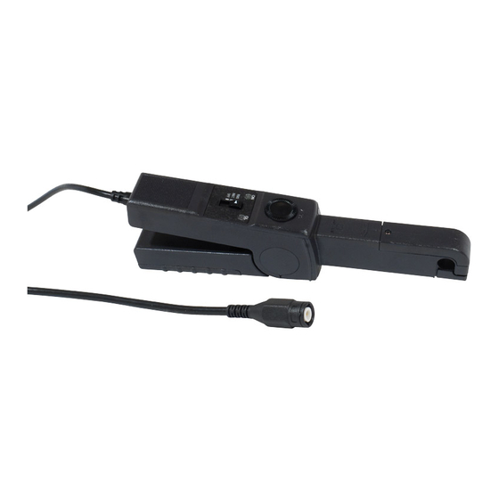
Chapitre I 1. PRÉSENTATION 1.1. PINCE Cette pince est une sonde de courant pour oscilloscope. Elle permet la mesure de courants continus ou alternatifs jusqu’à 20 A crête sans ouvrir le circuit électrique. Voyant vert ON/OFF Réglage et témoin de pile. du zéro. -
Página 7: Adaptateur Secteur
Chapitre I 1.2. ADAPTATEUR SECTEUR L’adaptateur secteur n’est livré qu’avec les pinces HX0102-K. Si les mesures durent longtemps, il permet de faire fonctionner la pince sur secteur et d’économiser ainsi la pile. B l o c s e c t e u r... -
Página 8: Mesure De Courant
Chapitre I 2. MESURE DE COURANT 2.1. PRINCIPE DE MESURE C’est une pince basée sur le principe de la mesure de flux dans un circuit magnétique par un capteur à effet Hall, ce qui permet la mesure de courant continu et alternatif. Sa sensibilité... - Página 9 Chapitre I „ La pince étant fermée et n’enserrant pas de conducteur, le commutateur étant sur la position INST, réglez le zéro de la pince à l’aide de la molette. En position RMS, le signal de sortie est uniquement positif et son évolution est plutôt lente, ce qui rend le réglage du zéro difficile.
- Página 10 Chapitre I Si le signal est trop faible, passez deux fois le conducteur dans la pince. N’oubliez pas alors de diviser par deux la valeur mesurée. Pour voir le signal instantané, placez le commutateur sur la position INST. Pour voir le signal RMS, placez le commutateur sur la position RMS.
-
Página 11: Adaptateur Secteur
Chapitre I 2.3. ADAPTATEUR SECTEUR L’adaptateur secteur n’est livré qu’avec les pinces HX0102-K. „ Déconnectez tout branchement de la pince et mettez le commutateur sur OFF. „ Retournez la pince puis, à l’aide d’un tournevis plat, dévissez la vis de la trappe à pile. -
Página 12: Caractéristiques
Chapitre I 3. CARACTÉRISTIQUES 3.1. CONDITIONS DE RÉFÉRENCE Grandeurs d’influence Valeurs de référence Température 23 ± 5 °C Humidité relative 20 à 75 %HR Fréquence du signal mesuré DC à 100 Hz Type de signal AC sinusoïdal Type de signal DC taux d’ondulation <... -
Página 13: Dépassement De Calibre
Chapitre I 3.2.1. MODE INST (SORTIE AC ET DC) Avec le zéro DC réalisé à ± 3 mA, pince immobile. Erreur de mesure au zéro due au bruit RMS : Paramètres Valeurs Résolution 3 mA Erreur intrinsèque sur l’amplitude (DC ou sinus) ±... -
Página 14: Variations Dans Le Domaine D'utilisation
Chapitre I 3.3. VARIATIONS DANS LE DOMAINE D’UTILISATION Pour les modes INST et RMS. Plage d’influence Grandeur d’influence Valeur typique Valeur maximale ou condition Température sur la mesure 0°C à + 50°C ± 800 ppm/°C ± 2000 ppm/°C Température sur le zéro DC 0°C à... - Página 15 Chapitre I 3.3.1. MODE INST (SORTIE AC ET DC) Plage d’influence Grandeur d’influence Valeur typique Valeur maximale ou condition Tension d’alimentation ± 5% ± 1 mA ± 5 mA DC à 2 kHz 1,5 mA Bruit RMS au zéro DC à 60 kHz 5 mA Bande passante à...
-
Página 16: Réponse En Fréquence
Chapitre I 3.4. RÉPONSE EN FRÉQUENCE 3.4.1. ERREUR D’AMPLITUDE Erreur (%) 00010 00100 01000 10000 100000 Fréquence (Hz) 3.4.2. ERREUR DE PHASE Phase (°) -100 -120 1000 10000 100000 Fréquence (Hz) Pince oscilloscope... - Página 17 Chapitre I 3.4.3. RÉPONSE À 14 KHZ ET 250 MA CRÊTE À CRÊTE Pince oscilloscope...
-
Página 18: Alimentation
Chapitre I 3.6. ALIMENTATION L’alimentation de l’appareil est réalisée par une pile 9 V alcaline (type 6LF22, CEI 6LR61, NEDA 1604). La tension nominale de fonctionnement se situe entre 6,5 et 10 V La consommation est de 20 mA typique et 30 mA au maximum. L’autonomie est de 20 heures typique soit 1200 mesures d’une minute. -
Página 19: Conformité Aux Normes Internationales
Chapitre I 3.8.2. ADAPTATEUR SECTEUR „ Dimensions hors tout (L x l x h) du boîtier : 96 mm x 58 mm x 86 mm. „ Dimensions hors tout (L x l x h) de la partie remplaçant la trappe à pile : 80 mm x 37 mm x 30 mm. „... -
Página 20: Maintenance
Chapitre I 4. MAINTENANCE Le fabricant ne pourra être tenu pour responsable de tout accident survenu suite à une réparation effectuée en dehors de son service après-vente ou des réparateurs agréés. 4.1. NETTOYAGE Déconnectez tout branchement de la pince et mettez le commutateur sur OFF. Utilisez un chiffon doux, légèrement imbibé... -
Página 21: Vérification Métrologique
Chapitre I 4.3. VÉRIFICATION MÉTROLOGIQUE Comme tous les appareils de mesure ou d’essais, une vérification périodique est nécessaire. Nous vous conseillons une vérification annuelle de cet appareil. Pour les vérifications et étalonnages, adressez-vous à nos laboratoires de métrologie accrédités COFRAC ou aux centres techniques MANUMESURE. -
Página 22: Garantie, Service
; „ des dommages dus à des chocs, chutes ou inondations. 6. POUR COMMANDER Pince oscilloscope HX0102 ....................HX0102 Livré dans une boîte en carton avec : „ une pile alcaline 9 V, „ une notice de fonctionnement 5 langues, „... - Página 23 Chapitre I Pince oscilloscope...
-
Página 24: Precautions For Use
Chapter II Thank you for purchasing a HX0102 or HX0102-K oscilloscope current probe. To obtain the best service from your unit: „ read these operating instructions carefully, „ comply with the precautions for use. WARNING, risk of DANGER! The operator agrees to refer to these instructions whenever this danger symbol appears. - Página 25 Chapter II „ Do not use the probe if it is open, damaged, or incorrectly reassembled. „ Do not expose the probe to sprays of water. „ Connect the probe only to oscilloscopes of which the overvoltage category and service voltage are greater than or equal to those of the device.
-
Página 26: Presentation
Chapter II 1. PRESENTATION 1.1. PROBE This clamp is a current probe for use with an oscilloscope. It can be used to measure direct and alternating currents up to 20 A peak without opening the circuit on which the measurement is made. G r e e n O N / O F F Zero... -
Página 27: Mains Adapter
Chapter II 1.2. MAINS ADAPTER The mains adapter is supplied only with HX0102-K clamps. If the measurements last a long time, it can be used to operate the probe on line power and so save the battery. Mains unit that transforms... -
Página 28: Current Measurement
Chapter II 2. CURRENT MEASUREMENT 2.1. MEASUREMENT PRINCIPLE This probe employs the principle of measuring the flux in a magnetic circuit by a Hall-effect sensor, allowing measurement of both direct and alternating currents. Its measurement sensitivity, its metrological capabilities, and its very good frequency response make it an ideal measurement accessory for oscilloscopes. - Página 29 Chapter II „ With the probe closed and not surrounding any conductor, and the switch set to INST, use the thumbwheel to adjust the zero of the probe. In the RMS setting, the output signal is always positive and its variations are rather slow, making it difficult to adjust the zero.
- Página 30 Chapter II If the signal is too weak, have the conductor pass through the probe twice. Do not forget to divide the measured value by two in this case. To view the instantaneous signal, set the switch to INST. To view the RMS signal, set the switch to RMS. Carefully check that the red OL indicator is off.
-
Página 31: Mains Adapter
Chapter II 2.3. MAINS ADAPTER The mains adapter is supplied only with HX0102-K clamps. „ Disconnect everything connected to the probe and set the switch to OFF. „ Turn the probe over, then, using a flat screwdriver, unscrew the screw of the battery compartment cover. -
Página 32: Characteristics
Chapter II 3. CHARACTERISTICS 3.1. REFERENCE CONDITIONS Quantity of influence Reference values Temperature 23 ± 5 °C Relative humidity 20 to 75 %RH Frequency of the signal measured DC to 100 Hz Type of AC signal sinusoidal Type of DC signal ripple <... - Página 33 Chapter II 3.2.1. INST MODE (AC AND DC OUTPUT) With the DC zero adjusted to within ±3mA, probe motionless. Zero measurement error due to RMS noise: Parameter Value Resolution Intrinsic error on amplitude (DC or sine wave) ± 1.5% ± 3mA Intrinsic error on phase at 3A and 50Hz <...
-
Página 34: Variations Within The Range Of Use
Chapter II 3.3. VARIATIONS WITHIN THE RANGE OF USE For the INST and RMS modes. Range of influence Quantity of influence Typical value Maximum value or condition Temperature on the measurement 0°C to + 50°C ± 800ppm/°C ± 2000ppm/°C Temperature on the DC zero 0°C to + 50°C ±... - Página 35 Chapter II 3.3.1. INST MODE (AC AND DC OUTPUT) Range of influence Quantity of influence Typical value Maximum value or condition Power supply voltage ±5% ±1mA ±5mA DC at 2kHz 1.5mA RMS noise at zero DC at 60kHz Pass band at 14A DC at 60kHz -3dB (see §6) Rise and fall time...
-
Página 36: Frequency Response
Chapter II 3.4. FREQUENCY RESPONSE 3.4.1. AMPLITUDE ERROR Error (%) 00010 00100 01000 10000 100000 Frequency (Hz) 3.4.2. PHASE ERROR Phase (°) -100 -120 1000 10000 100000 Frequency (Hz) Oscilloscope current probe... - Página 37 Chapter II 3.4.3. RESPONSE AT 14KHZ AND 250MA PEAK-TO-PEAK Oscilloscope current probe...
-
Página 38: Power Supply
Chapter II 3.6. POWER SUPPLY The instrument is powered by a 9V alkaline battery (type 6LF22, CEI 6LR61, NEDA 1604). The nominal operating voltage is between 6.5 and 10V The consumption is 20mA typical and 30mA maximum. The battery life is 20 hours typical or 1,200 one-minute measurements. When the green (ON) indicator no longer lights, it is time to replace the battery (see §4.2). -
Página 39: Compliance With International Standards
Chapter II 3.8.2. MAINS ADAPTER „ Overall dimensions (L x W x H) of the housing: 96mm x 58mm x 86mm. „ Overall dimensions (L x W x H) of the part replacing the battery compartment cover: 80mm x 37mm x 30mm. „... -
Página 40: Maintenance
Chapter II 4. MAINTENANCE The manufacturer cannot be held liable for any accident that occurs following a repair not performed by its customer service department or by an approved repairer. 4.1. CLEANING Disconnect everything connected to the instrument and set the switch to OFF. Use a soft cloth, dampened with soapy water. -
Página 41: Metrological Check
Chapter II 4.3. METROLOGICAL CHECK Like all measuring or testing devices, regular instrument verification is necessary. This instrument should be checked at least once a year. For checks and calibrations, contact one of our accredited metrology laboratories (information and contact details available on request), at our Chauvin Arnoux subsidiary or the branch in your country. -
Página 42: Warranty, Service
„ adaptation to a particular application not anticipated in the definition of the equipment or not indicated in the user manual; „ damage caused by shocks, falls, or floods. 6. TO ORDER HX0102 current oscilloscope probe .................. HX0102 Delivered in a cardboard box with: „ one 9V alkaline battery, „ one user’s manual in 5 languages, „... - Página 43 Chapter II Oscilloscope current probe...
-
Página 44: Sicherheitshinweise
Kapitel III Sie haben einen HX0102 bzw. HX0102-K Zangenstromwandler erstanden, wir danken Ihnen für Ihr Vertrauen. Damit die optimale Nutzung des Geräts gewährleistet ist: „ Lesen Sie aufmerksam diese Bedienungsanleitung, „ Beachten Sie genau die Benutzungshinweise. ACHTUNG, GEFAHRENRISIKO! Sobald dieses Gefahrenzeichen auftritt, ist der Bediener verpflichtet, die Anleitung zu Rate zu ziehen. - Página 45 Kapitel III „ Die Zange nur geöffnet, unbeschädigt und richtig montiert verwenden. „ Zange vor Spritzwasser schützen. „ Schließen Sie die Zange nur an ein Oszilloskop an, dessen Überspannungskategorie und Betriebsspannung dem Messgerät entspricht. „ Vermeiden Sie die Nähe zu anderen Leitern, die Störfelder schaffen könnten. „...
-
Página 46: Präsentation
Kapitel III 1. PRÄSENTATION 1.1. ZANGENSTROMWANDLER Dieser Zangenstromwandler ist eine Oszilloskop-Stromsonde. Er misst Gleich- und Wechselströme bis 20 A Scheitel, ohne dass der Stromkreis geöffnet werden muss. Grüne Anzeigelampe O N / O F F u n d Nullpunkteinstellung. Batterieladestand. Stromrichtung. -
Página 47: Netzadapter
Kapitel III 1.2. NETZADAPTER Netzadapter werden nur mit dem Modell HX0102-K mitgeliefert. Bei längeren Messungen hat man damit die Möglichkeit, den Zangenstromwandler ans Netz anzuschließen und die Batterie zu schonen. N e t z a d a p t e r , d e r Stelle zum Anschließen... -
Página 48: Strommessungen
Kapitel III 2. STROMMESSUNGEN 2.1. MESSGRUNDLAGE Der Zangenstromwandler beruht auf der Messung der Flüsse in einem Magnetkreis mittels Halleffekt- Stromwandler, womit Gleich- und Wechselstrom gemessen werden kann. Dieser Zangenstromwandler lässt sich dank seiner Messempfindlichkeit, Messgenauigkeit und ausgezeichnetem Frequenzgang als Messzubehör für Oszilloskope verwenden. Die Resultante am Ausgang ist Spannung. - Página 49 Kapitel III „ Für die Nullpunkteinstellung mit Hilfe des Einstellrädchens muss die Zange geschlossen sein, darf keinen Leiter umspannen und der Schalter muss auf INST stehen. In RMS-Stellung wird nur ein positives Signal ausgeben, welches sich langsam ändert. Dadurch ist eine Nullpunkteinstellung hier schwierig. Aus diesem Grund sollte die Nullpunkteinstellung in Schalterstellung INST erfolgen.
- Página 50 Kapitel III Bei zu schwachem Signal sollte man den Leiter zwei Mal mit der Zange messen. In diesem Fall nicht vergessen, den Messwert durch zwei zu teilen! Zur Anzeige des Ist-Signals stellt man den Schalter auf INST. Zur Anzeige des RMS-Signals stellt man den Schalter auf RMS.
-
Página 51: Netzadapter
Kapitel III 2.3. NETZADAPTER Netzadapter werden nur mit dem Modell HX0102-K mitgeliefert. „ Den Zangenstromwandler von jeder Verbindung trennen und Schalter auf OFF stellen. „ Drehen Sie die Zange um und lösen Sie die Schrauben des Batteriefachdeckels mit einem flachen Schraubendreher. -
Página 52: Technische Daten
Kapitel III 3. TECHNISCHE DATEN 3.1. REFERENZBEDINGUNGEN Einflussgrößen Referenzwerte Temperatur 23 ± 5 °C Relative Luftfeuchte 20 bis 75 % r.F. Signalfrequenz des Messsignals DC bei 100 Hz AC-Signalform Sinus DC-Signalform Welligkeitsfaktor <0,1% Batteriespannung 9 V ± 5 % ≥ 1 Minute Einschalten des Zangenstromwandlers Leiterposition Mittig in der Messspule... - Página 53 Kapitel III 3.2.1. INST-MODUS (AUSGANG AC UND DC) DC-Nullpunkt auf ±3mA, Zange unbeweglich. Nullpunkt-Messungenauigkeit wegen RMS-Rauschen: Parameter Werte Auflösung 3 mA Eigenunsicherheit Amplitude (DC oder Sinus) ± 1,5 % ± 3 mA Eigenunsicherheit Phase bei 3 A und 50 Hz <...
-
Página 54: Schwankungen Im Einsatzbereich
Kapitel III 3.3. SCHWANKUNGEN IM EINSATZBEREICH In beiden Modi INST und RMS. Einflussbereich Einflussgröße Typischer Wert Höchstwert oder Umstand Temperatur beim Messen 0 °C bis + 50 °C ± 800 ppm/°C ± 2000 ppm/°C Temperatur bei DC-Nullpunkt 0 °C bis + 50 °C ±... - Página 55 Kapitel III 3.3.1. INST-MODUS (AUSGANG AC UND DC) Einflussbereich Einflussgröße Typischer Wert Höchstwert oder Umstand Stromversorgung ± 5% ± 1 mA ± 5 mA DC bei 2 kHz 1,5 mA RMS-Rauschen Nullpunkt DC bei 60 kHz 5 mA Bandbreite bei ± 14A DC bei 60 kHz - 3 dB (siehe §...
-
Página 56: Frequenzgang
Kapitel III 3.4. FREQUENZGANG 3.4.1. AMPLITUDENFEHLER Fehler (%) 00010 00100 01000 10000 100000 Frequenz (Hz) 3.4.2. PHASENFEHLER Phasen (°) -100 -120 1000 10000 100000 Frequenz (Hz) Zangenstromwandler... - Página 57 Kapitel III 3.4.3. GANG BEI 14KHZ UND 250MA PEAK-TO-PEAK Zangenstromwandler...
-
Página 58: Stromversorgung
Kapitel III 3.6. STROMVERSORGUNG Das Gerät wird mit einer 9V Alkalibatterie (6LF22, CEI 6LR61, NEDA 1604) versorgt. Nennbetriebsspannung zwischen 6,5 und 10V Typischer Stromverbrauch 20mA, Höchstwert 30mA. Autonomie: durchschnittlich 20 Stunden bzw. 1 200 einminütige Messungen. Leuchtet die grüne Anzeigelampe (ON) nicht mehr, muss die Batterie gewechselt werden (siehe Kap. 4.2). 3.7. -
Página 59: Konformität Mit Internationalen Normen
Kapitel III 3.8.2. NETZADAPTER „ Gesamtmaße (L x B x H) des Gehäuses: 96mm x 58mm x 86mm. „ Gesamtmaße (L x B x H) des Adapterteils, das anstelle des Batteriefachs eingelegt wird: 80mm x 37mm x 30mm. „ Gewicht: ca. 450g. „... -
Página 60: Wartung
Kapitel III 4. WARTUNG Der Hersteller kann nicht für Unfälle oder Schäden haftbar gemacht werden, die auf eine außerhalb des Kundendienstes des Herstellers oder von nicht zugelassenen Reparaturwerkstätten durchgeführte Reparatur des Gerätes zurückzuführen sind. 4.1. REINIGUNG Den Zangenstromwandler von jeder Verbindung trennen und Schalter auf OFF stellen. Mit einem leicht mit Seifenwasser angefeuchteten Tuch reinigen. -
Página 61: Messtechnische Überprüfung
Kapitel III „ Schließen Sie die neue Batterie (9V Alkalibatterie 6LF22) an. „ Legen Sie das Batteriefach wieder ein und schrauben Sie es wieder zu. 4.3. MESSTECHNISCHE ÜBERPRÜFUNG Wie auch bei anderen Mess- oder Prüfgeräten ist eine regelmäßige Geräteüberprüfung erforderlich. Es wird mindestens eine einmal jährlich durchgeführte Überprüfung dieses Gerätes empfohlen. -
Página 62: Garantie
„ Anpassung des Geräts an nicht vorgesehene und nicht in der Anleitung aufgeführte Verwen- dungszwecke; „ Schäden durch Stöße, Herunterfallen, Überschwemmung. 6. BESTELLANGABEN Zangenstromwandler HX0102 ................... HX0102 Lieferung in Karton mit: „ 9V Alkalibatterie „ Betriebsanleitung in 5 Sprachen „ Prüfzertifikat. - Página 63 Kapitel III Zangenstromwandler...
- Página 64 Capitolo IV Avete appena acquistato una pinza oscilloscopio HX0102 o HX0102-K e vi ringraziamo per la fiducia che ci avete accordato. Per ottenere le migliori prestazioni dal vostro strumento: „ seguite attentamente le presenti istruzioni per l’uso. „ rispettate le precauzioni d’uso.
- Página 65 Capitolo IV „ Rispettare le condizioni d’uso, ossia temperatura, umidità, altitudine, livello di inquinamento e luogo d’uso. „ Non utilizzate la pinza se è aperta, deteriorata o rimontata male. „ Non sottoponete la pinza a spruzzi d’acqua. „ Allacciate la pinza solo su oscilloscopi la cui categoria di sovratensione e la tensione di servizio è superiore o uguale a quella dell’apparecchio.
-
Página 66: Presentazione
Capitolo IV 1. PRESENTAZIONE 1.1. PINZA Questa pinza è una sonda di corrente per oscilloscopio. Essa permette la misura di correnti continue o alternate fino a 20 A cresta senza aprire il circuito elettrico. Spia verde ON/OFF e Regolazione indicatore della pila. dello zero. -
Página 67: Adattatore Rete
Capitolo IV 1.2. ADATTATORE RETE L’adattatore di rete è fornito solo con le pinze HX0102-K. Se le misure durano a lungo l’adattatore permette di fare funzionare la pinza su rete il che economizza la pila. Blocco rete che trasforma Parte di sostituzione... -
Página 68: Misura Della Corrente
Capitolo IV 2. MISURA DELLA CORRENTE 2.1. PRINCIPIO DELLA MISURA E’ una pinza basata sul principio della misura di flusso in un circuito magnetico mediante un sensore ad effetto Hall, il che permette la misura della corrente continua e alternata. La sua sensibilità... - Página 69 Capitolo IV „ Quando la pinza è chiusa senza serrare il conduttore, il commutatore posizionato su INST, regolate lo zero della pinza mediante la rotella. In posizione RMS, il segnale d’uscita è solo positivo e la sua evoluzione è piuttosto lenta, il che rende difficile la regolazione dello zero.
- Página 70 Capitolo IV Se il segnale è troppo debole, passate due volte il conduttore nella pinza. Non dimenticate allora di dividere per due il valore misurato. Per vedere il segnale istantaneo, posizionate il commutatore su INST. Per vedere il segnale RMS, posizionate il commutatore su RMS.
-
Página 71: Adattatore Rete
Capitolo IV 2.3. ADATTATORE RETE L’adattatore rete viene fornito solo con le pinze HX0102-K. „ Disinserite ogni allacciamento della pinza e mettete il commutatore su OFF. „ Girate la pinza dopodiché mediante un cacciavite piatto, svitate la vite dello sportello della pila. -
Página 72: Caratteristiche
Capitolo IV 3. CARATTERISTICHE 3.1. CONDIZIONI DI RIFERIMENTO Grandezza d’influenza Valori di riferimento Temperatura 23 ± 5 °C Umidità relativa 20 a 75 %HR Frequenza del segnale misurato DC a 100 Hz Tipo di segnale AC sinusoidal Tipo di segnale DC tasso di ondulazione <... - Página 73 Capitolo IV 3.2.1. MODO INST (USCITA AC E DC) Con lo zero DC realizzato a ± 3 mA, pinza immobile. Errore di misura allo zero a causa della rumorosità RMS: Parametri Valori Risoluzione 3 mA Errore intrinseco sull’ampiezza (DC o seno) ±...
-
Página 74: Variazioni Nel Campo D'utilizzo
Capitolo IV 3.3. VARIAZIONI NEL CAMPO D’UTILIZZO Per i modi INST e RMS. Campo d’influenza Grandezza d’influenza Valore tipico Valore massimo o condizione Temperatura sulla misura 0 °C a + 50 °C ± 800 ppm/°C ± 2000 ppm/°C Temperatura sullo zero DC 0 °C a + 50 °C ±... - Página 75 Capitolo IV 3.3.1. MODO INST (USCITA AC E DC)) Campo d’influenza Grandezza d’influenza Valore tipico Valore massimo o condizione Tensione d’alimentazione ± 5% ± 1 mA ± 5 mA DC a 2 kHz 1,5 mA Rumorosità RMS a zero DC a 60 kHz 5 mA Banda passante a 14 A DC a 60 kHz...
-
Página 76: Risposta In Frequenza
Capitolo IV 3.4. RISPOSTA IN FREQUENZA 3.4.1. ERRORE D’AMPIEZZA Errore (%) 00010 00100 01000 10000 100000 Frequenza (Hz) 3.4.2. ERRORE DI FASE Fase (°) -100 -120 1000 10000 100000 Frequenza (Hz) Pinza oscilloscopio... - Página 77 Capitolo IV 3.4.3. RISPOSTA A 14 KHZ E 250 MA CRESTA A CRESTA Pinza oscilloscopio...
-
Página 78: Alimentazione (Hz)
Capitolo IV 3.6. ALIMENTAZIONE (HZ) L’alimentazione dello strumento avviene mediante una pila a 9 V alcalina (tipo 6LF22, CEI 6LR61, NEDA 1604). La tensione nominale di funzionamento è compresa fra 6,5 e 10 V Consumo: 20 mA (tipico) e 30 mA (massimo). Autonomia: 20 ore (tipico) ossia 1200 misure di un minuto. -
Página 79: Conformità Alle Norme Internazionali
Capitolo IV 3.8.2. ADATTATORE RETE „ Dimensioni totali (L x l x h) del quadro: 96 mm x 58 mm x 86 mm. „ Dimensioni totali (L x l x h) della parte che sostituisce lo sportello della pila: 80 mm x 37 mm x 30 mm. „... -
Página 80: Manutenzione
Capitolo IV 4. MANUTENZIONE Il produttore non è responsabile per dei guasti successivi a riparazioni effettuate da un servizio di assistenza o da centri di assistenza non autorizzati. 4.1. PULIZIA Disinserite ogni allacciamento dello strumento e mettete il commutatore su OFF. Utilizzare un panno soffice, inumidito con acqua saponata. -
Página 81: Verifica Metrologica
Capitolo IV 4.3. VERIFICA METROLOGICA Per tutti gli apparecchi di misura e di test, è necessaria una verifica periodica. Vi consigliamo almeno una verifica annuale dello strumento. Per le verifiche e le calibrazioni, rivolgetevi ai nostri laboratori di metrologia accreditati (informazioni e recapiti su richiesta), alla filiale Chauvin Arnoux del Vostro paese o al vostro agente. -
Página 82: Garanzia
„ danni dovuti ad urti, cadute o a fortuito contatto con l’acqua. 6. PER ORDINARE Pinza oscilloscopio HX0102 ....................HX0102 Fornito in una scatola di cartone con: „ una pila alcalina 9 V, „ un libretto d’istruzioni in 5 lingue, „... - Página 83 Capitolo IV Pinza oscilloscopio...
-
Página 84: Precauciones De Uso
Capitulo V Usted acaba de adquirir una pinza para osciloscopio HX0102 o HX0102-K y le agradecemos la confianza que ha depositado en nosotros. Para obtener el mejor servicio de su equipo: lea atentamente el manual de funcionamiento, „ respete las precauciones de empleo. - Página 85 Capitulo V „ Respete las condiciones de uso, es decir la temperatura, la humedad, la altitud, el grado de contaminación y el lugar de uso. „ No utilice la pinza si está abierta, dañada o mal montada. „ No deje que se moje la pinza. „...
-
Página 86: Presentación
Capitulo V 1. PRESENTACIÓN 1.1. PINZA Esta pinza es una sonda de corriente para osciloscopio. Permite la medida de corrientes continuas o alternas hasta 20 A pico sin abrir el circuito eléctrico. Piloto verde de ON/OFF Ajuste (Encendido/Apagado) e del cero. indicador de pila. -
Página 87: Adaptador De Red Eléctrica
Capitulo V 1.2. ADAPTADOR DE RED ELÉCTRICA El adaptador de red eléctrica se entrega únicamente con las pinzas HX0102-K. Si las medidas duran mucho tiempo, permite que funcione la pinza con la red eléctrica y así ahorrar la pila. Parte de cambio B l o q u e d e r e d q u e transforma la tensión de... -
Página 88: Medida De Corriente
Capitulo V 2. MEDIDA DE CORRIENTE 2.1. PRINCIPIO DE MEDIDA Se trata de una pinza basada en el principio de la medida de flujo en un circuito magnético por un sensor de efecto Hall, lo que permite la medida de corriente continua y alterna. Su sensibilidad de medida, sus prestaciones metrológicas y su muy buena respuesta en frecuencia la destinan a un uso como accesorio de medida para osciloscopios. - Página 89 Capitulo V „ Con la pinza cerrada no abrazando ningún conductor y con el interruptor en la posición INST, ajuste el cero de la pinza utilizando la rueda. En posición RMS, la señal de salida es únicamente positiva y su evolución es más bien lenta, dificultando el ajuste del cero.
-
Página 90: Desconexión
Capitulo V Si la señal es demasiado débil, pase dos veces el conductor dentro de la pinza. No olvide entonces dividir por dos el valor medido. Para ver la señal instantánea, posicione el conmutador en INST. Para ver la señal RMS, posicione el conmutador en RMS. -
Página 91: Adaptador De Red Eléctrica
Capitulo V 2.3. ADAPTADOR DE RED ELÉCTRICA El adaptador de red eléctrica se entrega únicamente con las pinzas HX0102-K. „ Desconecte cualquier cable de la pinza y posicione el conmutador en OFF. „ Dé la vuelta a la pinza y, con un tornillo plano, desatornille el tornillo de la tapa de la pila. -
Página 92: Características
Capitulo V 3. CARACTERÍSTICAS 3.1. CONDICIONES DE REFERENCIA Magnitudes de influencia Valores de referencia Temperatura 23 ± 5 °C Humedad relativa 20 a 75 %HR Frecuencia de la señal medida DC a 100 Hz Tipo de señal AC sinusoidal Tipo de señal DC Factor de rizado <... -
Página 93: Modo Inst (Salida Ac Y Dc)
Capitulo V 3.2.1. MODO INST (SALIDA AC Y DC) Con el cero DC ajustado a ±3 mA, pinza inmóvil. Error de medida al cero debido al ruido RMS: Parámetros Valores Resolución 3 mA Error intrínseco en la amplitud (DC o sino) ±... -
Página 94: Variaciones En El Rango De Utilización
Capitulo V 3.3. VARIACIONES EN EL RANGO DE UTILIZACIÓN Para los modos INST y RMS. Rango de influencia Magnitud de influencia Valor típico Valor máximo o condición Temperatura en la medida 0°C a + 50°C ± 800 ppm/°C ± 2.000 ppm/°C Temperatura en el cero DC 0°C a + 50°C ±... - Página 95 Capitulo V 3.3.1. MODO INST (SALIDA AC Y DC) Rango de influencia Magnitud de influencia Valor típico Valor máximo o condición Tensión de alimentación ± 5% ± 1 mA ± 5 mA DC a 2 kHz 1,5 mA Ruido RMS al cero DC a 60 kHz 5 mA Ancho de banda a 14 A...
-
Página 96: Respuesta En Frecuencia
Capitulo V 3.4. RESPUESTA EN FRECUENCIA 3.4.1. ERROR DE AMPLITUD Error (%) 00010 00100 01000 10000 100000 Frecuencia (Hz) 3.4.2. ERROR DE FASE Fase (°) -100 -120 1000 10000 100000 Frecuencia (Hz) Pinza para osciloscopio... -
Página 97: Respuesta A 14 Khz Y 250 Ma Pico A Pico
Capitulo V 3.4.3. RESPUESTA A 14 KHZ Y 250 MA PICO A PICO Pinza para osciloscopio... -
Página 98: Alimentación
Capitulo V 3.6. ALIMENTACIÓN La alimentación del instrumento está realizada por una pila de 9 V alcalina (tipo 6LF22, CEI 6LR61, NEDA 1604). La tensión nominal de funcionamiento se sitúa entre 6,5 y 10 Vdc. El consumo típico es de 20 mA y 30 mA como máximo. La autonomía típica es de 20 horas, es decir 1.200 medidas de un minuto. -
Página 99: Conformidad Con Las Normas Internacionales
Capitulo V 3.8.2. ADAPTADOR DE RED ELÉCTRICA „ Dimensiones totales (LxAnxAl) de la carcasa: 96 mm x 58 mm x 86 mm. „ Dimensiones totales (LxAnxAl) de la parte que sustituye a la tapa de la pila: 80 mm x 37 mm x 30 mm. „... -
Página 100: Mantenimiento
Capitulo V 4. MANTENIMIENTO El fabricante no se hará responsable de cualquier accidente que pudiera derivarse de una reparación no realizada por su servicio postventa o por reparadores autorizados. 4.1. LIMPIEZA Desconecte cualquier conexión del instrumento y ponga el conmutador en posición OFF. Limpiar el instrumento con un paño suave ligeramente empadado con agua jabonosa. -
Página 101: Comprobación Metrológica
Capitulo V 4.3. COMPROBACIÓN METROLÓGICA Al igual que todos los instrumentos de medida o de prueba, es necesario realizar una verificación periódica. Les aconsejamos por lo menos una verificación anual de este instrumento. Para las verificaciones y calibraciones, contacte con nuestros laboratorios de metrología acreditados (solicítenos información y datos), con la filial Chauvin Arnoux o con el agente de su país. -
Página 102: Garantía
„ se han producido daños causados por golpes, caídas o inundaciones. 6. PARA PEDIDOS Pinza para osciloscopio HX0102 ..................HX0102 Suministrada en una caja de cartón con: „ una pila alcalina de 9 V, „ un manual de instrucciones en 5 idiomas, „... - Página 103 Capitulo V Pinza para osciloscopio...
- Página 104 METRIX Parc des Glaisins 6, avenue du Pré de Challes 74940 ANNECY LE VIEUX Tél. 33 04 50 64 22 22 - Fax 33 04 50 64 22 00...