
Manuales relacionados para Allmatic Hyper 400


Resumen de contenidos para Allmatic Hyper 400
- Página 1 HYPER Operatore irreversibile ambidestro per cancelli ad ante battenti. 6-1624982 - ITALIANO - rev.3 - 03/11/2021...
-
Página 2: Tabla De Contenido
INDICE 1. AVVERTENZE GENERALI SULLA SICUREZZA 2. DESCRIZIONE 3. ELENCO PACKAGING, ACCESSORI ED INGOMBRI 4. VISTA PRODOTTO E CARATTERISTICHE TECNICHE 5. VERIFICHE PRELIMINARI 6. INSTALLAZIONE 7. MANUTENZIONE 8. SMALTIMENTO DEL PRODOTTO 9. GARANZIA 2 - Italiano 6-1624982 - rev.3 - 03/11/2021... -
Página 3: Avvertenze Generali Sulla Sicurezza
Prima di installare il prodotto è obbligatorio leggere il documento relativo alle AVVERTENZE DI SICUREZZA GENERALI a corredo del prodotto. Documento 6-1620001. Il foglio integrativo è scaricabile anche dal sito www.allmatic.com. 2. DESCRIZIONE Motoriduttore irreversibile ambidestro per cancelli a battente con ante lunghe fino a 4,5 m e di max 300kg. -
Página 4: Elenco Packaging, Accessori Ed Ingombri
3. ELENCO PACKAGING, ACCESSORI ED INGOMBRI HYPER HYPER Motoriduttore per cancelli ad ante battenti completo di kit di montaggio composto da: staffe di fissaggio, condensatore di spunto, Motoriduttore per cancelli ad ante battenti completo di kit di montaggio composto da: staffe di fissaggio, condensatore di spunto, chiave di sblocco e minuteria. -
Página 5: Con Finecorsa Interni (1 O 2)
STAFFA ANTERIORE DI FISSAGGIO ø 10.5 ø 10.5 ø 10.5 ø 11 ø 11 SENZA FINECORSA INTERNI 790 (HYPER 400) 990 (HYPER 600) CON FINECORSA INTERNI (1 o 2) 810 (HYPER 400) 1010 (HYPER 600) 6-1624982 - rev.3 - 03/11/2021 Italiano - 5... -
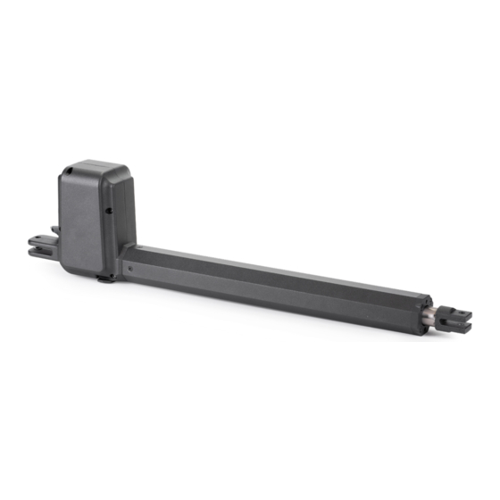
Página 6: Vista Prodotto E Caratteristiche Tecniche
Punto di fissaggio per staffa posteriore Cavo di alimentazione motore Punto di fissaggio per staffa anteriore Chiave di sblocco Viti per la regolazione dei finecorsa interni (opzionali) TABELLA 2 - Caratteristiche tecniche HYPER 400 CARATTERISTICHE TECNICHE U.M. HYPER 400 Centrale di comando consigliata... - Página 7 IN NESSUN CASO SUPERARE I PESI E LE DIMENSIONI MASSIME INDICATE IN QUESTE TABELLE. UTILIZZARE SEMPRE I RALLENTAMENTI IMPOSTATI DA CENTRALINA PER IL MOVIMENTO DEL CANCELLO. HYPER 400 230Vac ATTENZIONE! Nel grafico accanto è riportato, come esempio esplicativo, la re- lazione tra peso e lunghezza dell'anta per il motoriduttore HYPER 400 230Vac.
-
Página 8: Verifiche Preliminari
5. VERIFICHE PRELIMINARI ZONA DI INTRAPPOLAMENTO LATO INTERNO ZONA DI INTRAPPOLAMENTO DELLA PROPRIETÀ ATTENZIONE! È obbligatorio uniformare le caratteristiche del cancello alle norme e leggi vigenti. La porta può essere automatizzata solo se in buono stato e se rispondente alla norma EN 12604. - L’anta non deve presentare porte pedonali. -
Página 9: Verifiche Sul Cancello
Via dell'Artigianato 1 DENOM 32026 -Borgo Valbelluna (Bl) tel. +39 0437 751175 fax +39 0437 751165 info@allmatic.com - www.allmatic.com Il presente disegno è di proprietà della CONDOTTI Predisporre sul sito di installazione i condotti per il passaggio dei cavi motori. -
Página 10: Consigli Di Installazione
5.3 CONSIGLI DI INSTALLAZIONE COSA SI PUÒ FARE: • Assicurarsi che il motore venga installato a livello. • Il motore deve essere installato ad almeno 50 mm dal bordo inferiore del cancello. • Il motore può essere installato nella parte superiore dell’anta del cancello. •... -
Página 11: Installazione
Tenere quindi presente che i valori possono variare leggermente e vanno preventivamente verificati. ABELLA 7 - HYPER 400 Quote di installazione consigliate W ( α ) 980 (110°) -
Página 12: Supporto Aggiuntivo
6.2 DETERMINARE LE MISURE DI INSTALLAZIONE (APERTURA VERSO L’ESTERNO) Prima di procedere al fissaggio delle staffe in dotazione è necessario determinare le quote di installazione A e B. Iniziare mettendo il cancello in posizione di "PORTA APERTA". Scegliere le misure di A e B dalle Tabelle 7 e 8 del paragrafo precedente, in base alla propria installazione ed in modo da ottenere il grado di apertura "α"... -
Página 13: Lato Sinistro
LATO SINISTRO LATO DESTRO 6.4 FISSARE LA STAFFA ANTERIORE AL CANCELLO Per la installazione della staffa di fissaggio anteriore seguire questi passi: Sbloccare il motore. Portare la anta del cancello in posizione di "PORTA CHIUSA". ATTENZIONE! Nel caso si stia installando il motore con apertura verso l'esterno portare la anta del cancello in posizione di "PORTA APERTA". - Página 14 6.5 REGOLAZIONE DEI FINECORSA INTERNI (OPZIONALI) CALAMITA FINECORSA di APERTURA FINECORSA di CHIUSURA Per la regolazione dei finecorsa interni (opzionali) procedere come segue: Sbloccare il motore ed aprire manualmente il cancello fino alla posizione di "PORTA APERTA". Avvicinare una calamita (non fornita) o una delle rondelle fornite nel kit sul corpo motore in corrispondenza del finecorsa di apertura fino a trovare il punto in cui rimane attaccata.
-
Página 15: Unità Di Controllo
6.6 COLLEGAMENTO ALLA CENTRALINA Effettuare i collegamenti alla centralina solo in assenza di tensione di alimentazione. Per i motoriduttori in versione 230Vac e 120Vac installare il condensatore in dotazione tra la Fase 1 e la Fase 2 del motore. Fare riferimento al manuale di installazione della centralina per lo schema di collegamento. TABELLA 9 - Colore dei cavi per motore 230Vac CONDENSATORE COLORE... - Página 16 ALLMATIC S.r.l 32026 Borgo Valbelluna - Belluno – Italy Via dell’Artigiano, n°1 – Z.A. Tel. 0437 751175 – 751163 r.a. Fax 0437 751065 www.allmatic.com - E-mail: info@allmatic.com...
- Página 17 HYPER Ambidextrous irreversible operator for swing door gates. 6-1624982 - ENGLISH - rev.3 - 03/11/2021...
- Página 18 INDEX 1. GENERAL SAFETY WARNINGS 2. DESCRIPTION 3. LIST OF PACKAGING, ACCESSORIES AND OVERALL DIMENSIONS 4. PRODUCT VIEW AND TECHNICAL CHARACTERISTICS 5. PRELIMINARY CHECKS 6. INSTALLATION 7. MAINTENANCE 8. PRODUCT DISPOSAL 9. WARRANTY 2 - English 6-1624982 - rev.3 - 03/11/2021...
-
Página 19: General Safety Warnings
Before installing the product it is mandatory to read the document related to the GENERAL SAFETY WARNINGS accompanying the product. Document 6-1620001. The additional sheet can also be downloaded from www. allmatic.com. 2. DESCRIPTION Ambidextrous irreversible gearmotor for swing gates with doors up to 4.5 m long and up to 300kg. -
Página 20: List Of Packaging, Accessories And Overall Dimensions
3. LIST OF PACKAGING, ACCESSORIES AND OVERALL DIMENSIONS HYPER HYPER Gearmotor for gates with hinged doors complete with assembly kit consisting of: fixing brackets, capacitor, unlocking key and Gearmotor for gates with hinged doors complete with assembly kit consisting of: fixing brackets, capacitor, unlocking key and hardware fasteners. - Página 21 ø 10.5 ø 10.5 ø 10.5 ø 11 ø 11 WITHOUT INTERNAL MECHANICAL STOPPERS 790 (HYPER 400) 990 (HYPER 600) WITH INTERNAL MECHANICAL STOPPERS (1 or 2) 810 (HYPER 400) 1010 (HYPER 600) 6-1624982 - rev.3 - 03/11/2021 English - 5...
-
Página 22: Product View And Technical Characteristics
Fixing point for front bracket Motor supply cable Screws for adjusting internal mechanical stoppers (op- Key to unlock tional) Release lever to unlock TABLE 2 - HYPER 400 technical characteristics TECHNICAL CHARACTERISTICS U.M. HYPER 400 Recommended control board BIOS2 24... - Página 23 HYPER 400 230Vac WARNING! In the graph next to it is reported, as an explanatory example, the relationship between weight and length of the door for the gearmo- tor HYPER 400 230vac. 6-1624982 - rev.3 - 03/11/2021 English - 7...
-
Página 24: Preliminary Checks
5. PRELIMINARY CHECKS ZONE OF ENTRAPMENT INTERNAL SIDE OF ZONE OF ENTRAPMENT THE PROPERTY WARNING! It is mandatory to conform the characteristics of the gate to the rules and laws in force. The door can be automated only if it is in good condition and complies with EN 12604. - The door shall not have pedestrian doors. -
Página 25: Checks On The Gate
Via dell'Artigianato 1 DENOM 32026 -Borgo Valbelluna (Bl) tel. +39 0437 751175 fax +39 0437 751165 info@allmatic.com - www.allmatic.com Il presente disegno è di proprietà della DUCT Prepare on the installation site the ducts for the passage of motor cables. - Página 26 5.3 ADVICE ON INSTALLATION WHAT YOU CAN DO: • Ensure that the motor is installed on level. • The motor shall be installed at least 50 mm from the lower edge of the gate door. • The motor can be installed at the top of the gate door. •...
-
Página 27: Installation
Keep in mind that values may vary slightly and must be checked in advance. TABLE 7 - HYPER 400 Recommended installation dimensions W ( α ) 980 (110°) - Página 28 6.2 DETERMINE THE INSTALLATION MEASUREMENTS (OUTWARD OPENING) Before fixing the supplied brackets it is necessary to determine the installation dimensions A and B. Start by putting the gate in position of "OPEN DOOR". Choose the sizes of A and B from Tables 7 and 8 of the previous paragraph, according to your installation and in order to obtain the desired degree of opening "α".
-
Página 29: Left Side
LEFT SIDE RIGHT SIDE 6.4 FASTEN THE FRONT BRACKET TO THE GATE To install the front bracket follow these steps: Unlock the motor. Bring the door of the gate to the position of "CLOSED DOOR". ATTENTION! In case you are installing the motor with opening to the outside bring the door of the gate in the position of "OPEN DOOR". - Página 30 6.5 ADJUSTMENT OF INTERNAL MECHANICAL STOPPERS (OPTIONAL) MAGNET MECHANICAL STOP OF OPENING MECHANICAL STOP OF CLOSING To adjust the internal mechanical stoppers (optional), proceed as follows: Unlock the motor and manually open the gate to the position of "OPEN DOOR". Approach a magnet (not supplied) or one of the washers provided in the kit on the motor body at the opening mechanical stopper until you find the point where it remains attached.
-
Página 31: Control Unit
6.6 CONNECTION TO THE CONTROL UNIT Make connections to the control unit only in the absence of power supply. For the 230Vac and 120Vac gearmotors, install the capacitor supplied between Phase 1 and Phase 2 of the motor. Please refer to the installation manual of the control unit for the connection diagram. TABLE 9 - Cable colour for 230Vac motor CAPACITOR COLOUR... - Página 32 ALLMATIC S.r.l 32026 Borgo Valbelluna - Belluno – Italy Via dell’Artigiano, n°1 – Z.A. Tel. 0437 751175 – 751163 r.a. Fax 0437 751065 www.allmatic.com - E-mail: info@allmatic.com...
- Página 33 HYPER Opérateur ambidextre irréversible pour ails battantes. 6-1624982 - FRANÇAIS - rev.3 - 03/11/2021...
- Página 34 INDEX 1. AVERTISSEMENTS GÉNÉRALES DE SECURITÉ 2. DESCRIPTION 3. LISTE DES EMBALLAGES, ACCESSOIRES ET DIMENSIONS GLOBALES 4. VUE DU PRODUIT ET CARACTÉRISTIQUES TECHNIQUES 5. VÉRIFICATIONS PRÉLIMINAIRES 6. MISE EN PLACE 7. MAINTENANCE 8. ÉLIMINATION DU PRODUIT 9. GARANTIE 2 - Français 6-1624982 - rev.3 - 03/11/2021...
-
Página 35: Avertissements Générales De Securité
Avant d’installer le produit il est obligatoire de lire le dossier concernant LES AVERTISSEMENTS GÉNÉRALES DE SECURITÉ fournies avec le produit. Dossier 6-1620001. Téléchargeable aussi à partir du site internet www. allmatic.com. 2. DESCRIPTION Motoréducteur ambidextre irréversible pour portails battants avec portes jusqu’à 4,5 m de longueur et jusqu’à 300 kg de poids. -
Página 36: Liste Des Emballages, Accessoires Et Dimensions Globales
3. LISTE DES EMBALLAGES, ACCESSOIRES ET DIMENSIONS GLOBALES HYPER HYPER Motoréducteur pour portails avec portes battantes complet avec kit de montage composé de : supports de fixation, condensateur, Motoréducteur pour portails avec portes battantes complet avec kit de montage composé de : supports de fixation, condensateur, clé... - Página 37 ø 10.5 ø 10.5 ø 10.5 ø 11 ø 11 SANS BUTÉE MÉCANIQUES INTERNES 790 (HYPER 400) 990 (HYPER 600) AVEC BUTÉE MÉCANIQUES INTERNES (1 ou 2) 810 (HYPER 400) 1010 (HYPER 600) 6-1624982 - rev.3 - 03/11/2021 Français - 5...
-
Página 38: Vue Du Produit Et Caractéristiques Techniques
Point de fixation du support avant Câble d’alimentation du moteur Vis de réglage des butée mécaniques internes (en option) Clé à déverrouiller Levier de déverrouillage TABLEAU 2 - CARACTERISTIQUES TECHNIQUES HYPER 400 CARACTÉRISTIQUES TECHNIQUES U.M. HYPER 400 Carte de commande recommandée... -
Página 39: Course De Tige Disponible
HYPER 400 230Vac AVERTISSEMENT ! Dans le graphique ci-contre est rapporté, à titre d’exemple explica- tif, la relation entre le poids et la longueur de la porte pour le moteur à engrenages HYPER 400 230vac. 6-1624982 - rev.3 - 03/11/2021 Français - 7... -
Página 40: Vérifications Préliminaires
5. VÉRIFICATIONS PRÉLIMINAIRES ZONE DE ENTRAPMENT CÔTÉ INTERNE DE ZONE DE ENTRAPMENT LA PROPRIÉTÉ ATTENTION! Il est obligatoire de conformer les caractéristiques de la porte aux règles et lois en vigueur. La porte ne peut être automatisée que si elle est en bon état et conforme à la norme EN 12604. - La porte ne doit pas comporter de portes pour piétons. -
Página 41: Préparation Du Site D'installation
Via dell'Artigianato 1 DENOM 32026 -Borgo Valbelluna (Bl) tel. +39 0437 751175 fax +39 0437 751165 info@allmatic.com - www.allmatic.com Il presente disegno è di proprietà della CONDUIT Préparer sur le site d’installation les gaines pour le passage des câbles du moteur. -
Página 42: Conseils Pour L'installation
5.3 CONSEILS POUR L’INSTALLATION CE QUE VOUS POUVEZ FAIRE : • S’assurer que le moteur est installé au niveau. • Le moteur doit être installé à au moins 50 mm du bord inférieur de la porte de la barrière. • Le moteur peut être installé en haut de la porte. •... -
Página 43: Mise En Place
Gardez à l’esprit que les valeurs peuvent varier légèrement et doivent être vérifiées à l’avance. TABLEAU 7 - HYPER 400 Dimensions d’installation recommandées W ( α ) 980 (110°) - Página 44 6.2 DÉTERMINER LES MESURES D’INSTALLATION (OUVERTURE EXTÉRIEURE) Avant de fixer les supports fournis, il est nécessaire de déterminer les dimensions d’installation A et B. Commencez par mettre la porte en position "OPEN DOOR". Choisissez les dimensions de A et B dans les tableaux 7 et 8 du paragraphe précédent, en fonction de votre installation et afin d’obtenir le degré...
-
Página 45: Côté Gauche
CÔTÉ GAUCHE CÔTÉ DROIT 6.4 FIXER LE SUPPORT AVANT À LA BARRIÈRE Pour installer le support avant, suivre ces étapes: Déverrouiller le moteur. Amener la porte du portail à la position "PORTE FERMÉE". ATTENTION! Dans le cas où vous installez le moteur avec ouver- ture à... - Página 46 6.5 RÉGLAGE DES BOUCHONS MÉCANIQUES INTERNES (FACULTATIF) MAGNET BUTÉE MÉCANIQUE DE L’OUVERTURE BUTÉE MÉCANIQUE DE CLÔTURE Pour régler les butées mécaniques internes (en option), procéder comme suit: Déverrouiller le moteur et ouvrir manuellement la porte à la position "OPEN DOOR". Approcher un aimant (non fourni) ou l’une des rondelles fournies dans le kit sur le corps du moteur à...
-
Página 47: Maintenance
6.6 CONNEXION À L’UNITÉ DE COMMANDE Ne raccorder l’unité de commande qu’en l’absence d’alimentation électrique. Pour les moteurs à engrenages 230Vac et 120Vac, installer le condensateur fourni entre les phases 1 et 2 du moteur. Consulter le manuel d’installation de l’unité de commande pour le schéma de connexion. TABLEAU 9 - Couleur des câbles du moteur 230Vac CONDENSATEUR COULEUR... - Página 48 ALLMATIC S.r.l 32026 Borgo Valbelluna - Belluno – Italy Via dell’Artigiano, n°1 – Z.A. Tel. 0437 751175 – 751163 r.a. Fax 0437 751065 www.allmatic.com - E-mail: info@allmatic.com...
- Página 49 HYPER Operador irreversible ambidiestro para puertas batientes. 6-1624982 - ESPAÑOL - rev.3 - 03/11/2021...
- Página 50 ÍNDICE 1. ADVERTENCIAS DE SEGURIDAD GENERAL 2. DESCRIPCIÓN 3. LISTA DE EMBALAJE, ACCESORIOS Y DIMENSIONES 4. VISTA DEL PRODUCTO Y CARACTERÍSTICAS TÉCNICAS 5. VERIFICACIONES PREVIAS 6. INSTALACIÓN 7. MANTENIMIENTO 8. ELIMINACIÓN DEL PRODUCTO 9. GARANTÍA 2 - Español 6-1624982 - rev.3 - 03/11/2021...
-
Página 51: Advertencias De Seguridad General
Antes de instalar el producto es obligatorio leer el documento relativo a las ADVERTENCIAS DE SEGURIDAD GENERAL en dotación con il producto. Documento 6-1620001. La página integrativa se puede descargar tambien del sitio www.allmatic.com. 2. DESCRIPCIÓN Motorreductor irreversible ambidiestro para cancelas batientes con puertas largas de hasta 4,5 m y de máximo 300kg. -
Página 52: Lista De Embalaje, Accesorios Y Dimensiones
3. LISTA DE EMBALAJE, ACCESORIOS Y DIMENSIONES HYPER HYPER Motorreductor para cancelas con puertas completo de kit de montaje compuesto por: soportes de fijación, condensador de Motorreductor para cancelas con puertas completo de kit de montaje compuesto por: soportes de fijación, condensador de arranque, llave de desbloqueo y minutería. -
Página 53: Soporte Trasero De Fijación
ø 10.5 ø 10.5 ø 10.5 ø 11 ø 11 SIN FINAL DE CARRERA INTERIOR 790 (HYPER 400) 990 (HYPER 600) CON FINAL DE CARRERA INTERIOR (1 o 2) 810 (HYPER 400) 1010 (HYPER 600) 6-1624982 - rev.3 - 03/11/2021... -
Página 54: Vista Del Producto Y Características Técnicas
Cable de alimentación del motor Punto de fijación para el soporte delantero Llave de desbloqueo Tornillos para el ajuste del extremo del recorrido interior (opcional) CUADRO 2 - Especificaciones técnicas HYPER 400 CARACTERÍSTICAS TÉCNICAS U.M. HYPER 400 Central de mando recomendada... -
Página 55: Recorrido Disponible Del Tallo
EN NINGÚN CASO SOBREPASAR LOS PESOS Y LAS DIMENSIONES MÁXIMAS INDICADAS EN ESTOS CUADROS. UTILICE SIEMPRE LAS RALENTIZACIONES ESTABLECIDAS POR CENTRALITA PARA EL MOVIMIENTO DE LA PUERTA. HYPER 400 230Vac ¡ATENCIÓN! En el gráfico de al lado se muestra, como ejemplo explicativo, la re- lación entre el peso y la longitud de la puerta para el motorreductor... -
Página 56: Verificaciones Previas
5. VERIFICACIONES PREVIAS ZONA DE APRISIONAMIENTO INTERIOR DE LA ZONA DE APRISIONAMIENTO PROPIEDAD ¡ATENCIÓN! Es obligatorio uniformar las características de la puerta a las normas y leyes vigentes. El puerto solo podrá automati- zarse si se encuentra en buen estado y si cumple la norma EN 12604. - La puerta no deberá... -
Página 57: Inspección De La Puerta
Via dell'Artigianato 1 DENOM 32026 -Borgo Valbelluna (Bl) tel. +39 0437 751175 fax +39 0437 751165 info@allmatic.com - www.allmatic.com Il presente disegno è di proprietà della CONDUCTOS Preparar en el lugar de instalación los conductos para el paso de los cables motores. -
Página 58: Consejos De Instalación
5.3 CONSEJOS DE INSTALACIÓN LO QUE PUEDE HACER: • Asegúrese de que el motor está instalado a nivel. • El motor se instalará como mínimo a 50 mm del borde inferior de la puerta. • El motor puede instalarse en la parte superior de la puerta. •... -
Página 59: Instalación
Por lo tanto, debe tenerse en cuenta que los valores pueden variar ligeramente y deben compro- barse previamente. CUADRO 7 - HYPER 400 Cantidad de instalación recomendada W ( α ) 980 (110°) 982 (110°) -
Página 60: Determinación De Las Medidas De Instalación (Abertura Exterior)
6.2 DETERMINACIÓN DE LAS MEDIDAS DE INSTALACIÓN (ABERTURA EXTERIOR) Antes de proceder a la fijación de los soportes suministrados, es necesario determinar las cuotas de instalación A y B. Comience colocando la puerta en la posición de "PUERTA ABIERTA". Elija las medidas de A y B de las Tablas 7 y 8 del párrafo anterior, de acuerdo a su instalación y para obtener el grado de apertura "α"... -
Página 61: Lado Izquierdo
LADO IZQUIERDO LADO DERECHO 6.4 ASEGURAR EL SOPORTE DELANTERO A LA PUERTA Para la instalación del soporte de fijación delantera siga estos pasos: Desbloquear el motor. Coloque la puerta de la puerta en la posición de "PUERTA CERRADA". ¡ATENCIÓN! En caso de que se esté instalando el motor con apertura hacia el exterior, llevar la puerta de la puerta a la posición de "PUERTA ABIERTA". -
Página 62: Ajuste Del Final De Carrera Interior (Opcional)
6.5 AJUSTE DEL FINAL DE CARRERA INTERIOR (OPCIONAL) IMÁN FINAL DE CARRERA de APERTURA FINAL DE CARRERA de CIERRE Para ajustar el final del recorrido interior (opcional), proceder de la manera siguiente: Desbloquear el motor y abrir manualmente la puerta hasta la posición de "PUERTA ABIERTA". Se aproxima un imán (no suministrado) o una de las arandelas suministradas en el kit del cuerpo del motor en el extremo de la carrera de apertura hasta encontrar el punto en el que permanece unida. -
Página 63: Mantenimiento
6.6 CONEXIÓN A LA CENTRALITA Realizar las conexiones a la unidad de control sólo en ausencia de tensión de alimentación. Para los motores en versiones 230Vac y 120Vac, instalar el condensador suministrado entre la fase 1 y la fase 2 del motor. Consulte el manual de instalación de la unidad de control para el esquema de conexión. - Página 64 ALLMATIC S.r.l 32026 Borgo Valbelluna - Belluno – Italy Via dell’Artigiano, n°1 – Z.A. Tel. 0437 751175 – 751163 r.a. Fax 0437 751065 www.allmatic.com - E-mail: info@allmatic.com...
- Página 65 HYPER Onomkeerbare reductiemotor voor draaipoorten. 6-1624982 - NEDERLANDSE - rev.3 - 03/11/2021...
- Página 66 INDEX 1. DE ALGEMENE VEILIGHEIDSWAARSCHUWINGEN 2. BESCHRIJVING 3. LIJST VAN VERPAKKINGEN, ACCESSOIRES EN TOTALE AFMETINGEN 4. PRODUCTWEERGAVE EN TECHNISCHE KENMERKEN 5. VOORAFGAANDE CONTROLES 6. INSTALLATIE 7. ONDERHOUD 8. VERWIJDERING VAN HET PRODUCT 9. GARANTIE 2 - Nederlandse 6-1624982 - rev.3 - 03/11/2021...
-
Página 67: De Algemene Veiligheidswaarschuwingen
Voordat u het product installeert, moet u het document met betrekking tot DE ALGEMENE VEILIGHEIDSWAAR- SCHUWINGEN die bij het product worden geleverd, lezen. Document 6-1620001. Het aanvullende blad kan ook worden gedownload van www.allmatic.com. 2. BESCHRIJVING Voor zowel links- als rechtshandig gebruik is een onomkeerbare aandrijving voor hekken met deuren tot 4.5 m lang en tot 300 kg. -
Página 68: Lijst Van Verpakkingen, Accessoires En Totale Afmetingen
3. LIJST VAN VERPAKKINGEN, ACCESSOIRES EN TOTALE AFMETINGEN HYPER HYPER Aandrijving voor hekken met scharnierende deuren compleet met montageset bestaande uit: Bevestigingsbeugels, condensator, Aandrijving voor hekken met scharnierende deuren compleet met montageset bestaande uit: Bevestigingsbeugels, condensator, ontgrendelingssleutel en bevestigingsmiddelen. ontgrendelingssleutel en bevestigingsmiddelen. AANDRIJVING DRAAIPUNTEN EN SLEUTEL... - Página 69 ø 10.5 ø 10.5 ø 10.5 ø 11 ø 11 ZONDER INTERNE MECHANISCHE AANSLAGEN 790 (HYPER 400) 990 (HYPER 600) MET INWENDIGE MECHANISCHE AANSLAGEN (1 OF 2) 810 (HYPER 400) 1010 (HYPER 600) 6-1624982 - rev.3 - 03/11/2021 Nederlandse - 5...
-
Página 70: Productweergave En Technische Kenmerken
Voedingskabel van de motor Schroeven voor het afstellen van interne mechanische Sleutel om te ontgrendelen aanslagen (optioneel) Laat de hendel los om te ontgrendelen TABEL 2 - TECHNISCHE kenmerken VAN HYPER 400 TECHNISCHE KENMERKEN U.M. HYPER 400 Aanbevolen bedieningspaneel BIOS2 24... - Página 71 TINGEN WORDEN OVERSCHREDEN. GEBRUIK ALTIJD DE DOOR DE REGELEENHEID INGESTELDE VERTRAGINGEN VOOR DE BEWE- GING VAN DE VEILIGHEIDSDEUR. HYPER 400 230Vac WAARSCHUWING! In de grafiek hiernaast wordt als verklarend voorbeeld de relatie tussen gewicht en lengte van de deur voor de gearmotor HYPER 400 230vac vermeld.
-
Página 72: Voorafgaande Controles
5. VOORAFGAANDE CONTROLES ZONE VAN INKAPSELING INTERNE KANT ZONE VAN INKAPSELING VAN HET ERF WAARSCHUWING! Het is verplicht om de kenmerken van de poort te voldoen aan de geldende regels en wetten. De deur kan alleen worden geautomatiseerd als deze in goede staat verkeert en voldoet aan en 12604. - de deur mag geen voetgangersdeuren hebben. -
Página 73: Controles Op De Poort
Via dell'Artigianato 1 DENOM 32026 -Borgo Valbelluna (Bl) tel. +39 0437 751175 fax +39 0437 751165 info@allmatic.com - www.allmatic.com Il presente disegno è di proprietà della KANAAL Bereid op de installatielocatie de kanalen voor op de doorgang van motorkabels. De kabels voor de aansluiting van de verschillende apparaten in een typische installatie staan in de onderstaande tabel en moeten geschikt zijn voor het type installatie. -
Página 74: Advies Over De Installatie
5.3 ADVIES OVER DE INSTALLATIE WAT U KUNT DOEN: • Zorg ervoor dat de motor horizontaal is gemonteerd. • De motor moet op ten minste 50 mm van de onderrand van de deur van de veiligheidsdeur worden geïnstalleerd. • De motor kan worden geïnstalleerd aan de bovenkant van de achterdeur. •... -
Página 75: Installatie
Houd er rekening mee dat de waarden enigszins kunnen verschillen en van tevoren moeten worden gecontroleerd. TABEL 7 - AANBEVOLEN installatieafmetingen VOOR HYPER 400 W ( α ) 980 (110°) 982 (110°) -
Página 76: Bepaal De Installatiematen (Naar Buiten Gerichte Opening)
6.2 BEPAAL DE INSTALLATIEMATEN (NAAR BUITEN GERICHTE OPENING) Voordat de meegeleverde beugels worden bevestigd, moeten de montageafmetingen A en B worden bepaald Begin door de achterwand in de stand „OPEN DEUR” te zetten. Kies de maten A en B uit tabel 7 en 8 van de vorige paragraaf, afhankelijk van uw installatie en om de gewenste mate van opening "α"... - Página 77 LINKERKANT RECHTERKANT 6.4 BEVESTIG DE VOORSTE BEUGEL AAN DE VEILIGHEIDSDEUR Volg deze stappen om de voorste steun te installeren: Ontgrendel de motor. Breng de deur van het hek in de stand „GESLOTEN DEUR”. LET OP! Als u de motor installeert met de opening naar buiten, brengt u de deur van het hek in de positie van "OPEN DEUR".
- Página 78 6.5 AFSTELLING VAN INTERNE MECHANISCHE STOPPEN (OPTIONEEL) MAGNEET MECHANISCHE AANSLAG VOOR HET OPENEN MECHANISCHE AANSLAG VOOR HET SLUITEN Ga als volgt te werk om de interne mechanische stoppen (optioneel) af te stellen: Ontgrendel de motor en open de veiligheidsdeur handmatig in de stand „OPEN DEUR”. Benader een magneet (niet meegeleverd) of een van de onderlegringen uit de kit op het motorhuis bij de mechanische stopper van de opening totdat u het punt vindt waar deze nog steeds is bevestigd.
-
Página 79: Aansluiting Op De Regeleenheid
6.6 AANSLUITING OP DE REGELEENHEID Maak alleen verbindingen met de regeleenheid als er geen voeding is. Voor de 230Vac- en 120VAC-versnellingsmotoren installeert u de condensator die wordt gevoed tussen fase 1 en fase 2 van de motor. Raadpleeg de installatiehandleiding van de regeleenheid voor het aansluitschema. CONDENSATOR TABEL 9 - Kabelkleur voor motor van 230 Vac PHASE 1... - Página 80 ALLMATIC S.r.l 32026 Borgo Valbelluna - Belluno – Italy Via dell’Artigiano, n°1 – Z.A. Tel. 0437 751175 – 751163 r.a. Fax 0437 751065 www.allmatic.com - E-mail: info@allmatic.com...