Tabla de contenido
Publicidad
Idiomas disponibles
Idiomas disponibles
Enlaces rápidos
ATTACH YOUR RECEIPT HERE
Serial Number
Questions, problems, missing parts? Before returning to your retailer, call our customer
service department at
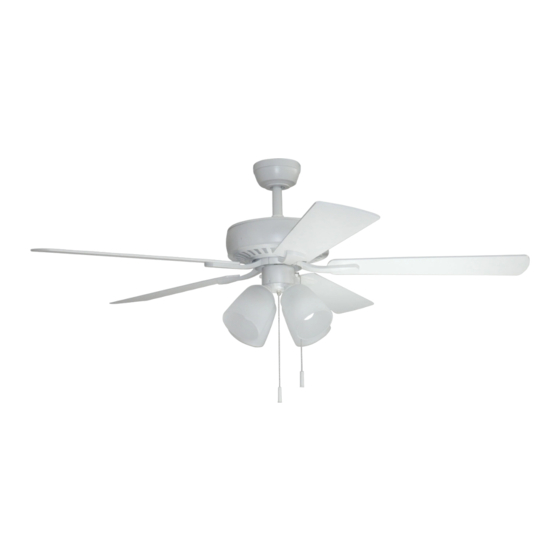
GRACE BAY CEILING FAN
Purchase Date
1-800-527-1292, 8:30 a.m. - 5 p.m., CST, Monday - Friday.
1
ITEM #1145468
1145469
MODEL #BDB52LW5LS
BDB52MBK5LS
Español p. 20
Publicidad
Capítulos
Tabla de contenido
Solución de problemas

Manuales relacionados para Harbor Breeze GRACE BAY BDB52LW5LS


Resumen de contenidos para Harbor Breeze GRACE BAY BDB52LW5LS
- Página 1 ITEM #1145468 1145469 GRACE BAY CEILING FAN MODEL #BDB52LW5LS BDB52MBK5LS Español p. 20 ATTACH YOUR RECEIPT HERE Serial Number Purchase Date Questions, problems, missing parts? Before returning to your retailer, call our customer service department at 1-800-527-1292, 8:30 a.m. - 5 p.m., CST, Monday - Friday.
-
Página 2: Tabla De Contenido
TABLE OF CONTENTS Safety Information .......................2 Package Contents .......................4 Hardware Contents ..........................5 Preparation ..........................5 Initial Installation ........................6 Downrod-Style Fan Mounting ....................8 Closemount-Style Fan Mounting ..................10 Wiring ..........................11 Final Installation .........................13 Operating Instructions .......................16 Care and Maintenance ......................17 Troubleshooting........................18 Limited Lifetime Warranty ....................19 Replacement Parts List .....................19 SAFETY INFORMATION READ AND SAVE THESE INSTRUCTIONS... - Página 3 SAFETY INFORMATION DANGER When using an existing outlet box, make sure the outlet box is securely attached to the building structure and can support the full weight of the fan. Failure to do this can result in serious injury or death.
-
Página 4: Package Contents
PACKAGE CONTENTS PART DESCRIPTION QUANTITY PART DESCRIPTION QUANTITY Canopy Mounting Screw Downrod (preassembled) Canopy Pin (preassembled) Mounting Bracket Clip (preassembled) (preassembled) Motor Housing Star Washer (preassembled) Glass Shade Light Kit Fitter Screw Blade (preassembled) Blade Arm Light Kit Fitter Balancing Kit Socket Ring Motor Screw (preassembled) -
Página 5: Hardware Contents
HARDWARE CONTENTS (shown actual size) Blade Fiber Screw Blade Washer Wire Qty. 15 Connector + 1 extra Qty. 15 Pull Chain + 1 extra Qty. 4 Extension Qty. 2 PREPARATION Before beginning assembly of product, make sure all parts are present. Place motor on carpet or on foam to avoid damage to finish. -
Página 6: Initial Installation
INITIAL INSTALLATION Turn off circuit breakers and wall switch to the fan supply line leads. DANGER: Failure to disconnect power supply prior to installation may result in serious injury or death. Determine mounting method to use. A. Downrod mount (standard or angled ceiling) B. -
Página 7: Important
INITIAL INSTALLATION 4a. Loosen canopy mounting screws (L) in slotted holes of canopy (B) and remove the other two canopy mounting screws (L) and star washers (O). Save for later use. Remove mounting bracket (C) from canopy (B). Secure mounting bracket (C) to outlet box (not STANDARD ANGLE MOUNT MOUNT... -
Página 8: Downrod-Style Fan Mounting
DOWNROD-STYLE FAN MOUNTING Remove pin (M) and clip (N) from downrod (A). Partially loosen preassembled set screws and nut in yoke at top of motor housing (D). Set Screw and Nut Yoke 2. Insert downrod (A) through canopy (B). Thread wires from motor housing (D) up through downrod (A). - Página 9 DOWNROD-STYLE FAN MOUNTING Depending on the length of downrod you use, you may need to cut the lead wires back to simplify the wiring. If you decide to cut back the lead wires, it is suggested you do so in the following manner: Ball Take the lead wires and make sure you have...
- Página 10 CLOSEMOUNT-STYLE FAN MOUNTNG Remove preassembled canopy cover from bottom of canopy (B). NOTE: It may be necessary to use a screwdriver (not included) to remove the canopy cover by tapping on the canopy cover from the inside of the canopy (B). NOTE: The downrod (A) and canopy cover are not used in this type of installation.
-
Página 11: Closemount-Style Fan Mounting
CLOSEMOUNT-STYLE FAN MOUNTING Temporarily hang fan on the tab on the mounting bracket (C) using one of the non-slotted holes in the canopy (B). WIRING WARNING: To reduce the risk of fire, electrical shock, or personal injury, wire connectors provided with this fan are designed to accept only one 12-gauge house wire and two lead wires from the fan. - Página 12 WIRING 1b. FAN CONTROLLED BY PULL CHAIN, FAN CONTROLLED BY PULL CHAIN, LIGHT BY WALL SWITCH FAN AND LIGHT CONTROLLED BY TWO WALL SWITCHES LIGHT BY WALL SWITCH: If you intend to control the fan light with a separate wall switch, connect BLACK wire from fan to BLACK wire 120V POWER FROM CEILING...
-
Página 13: Final Installation
FINAL INSTALLATION Lift canopy (B) to mounting bracket (C) and align slotted holes in canopy (B) with loosened canopy mounting screws (L) in mounting Closemount Downrod bracket (C). Twist canopy (B) to lock, then Option Option insert the two canopy mounting screws (L) and star washers (O) previously removed (Step 4a, page 7). - Página 14 FINAL INSTALLATION 4. Remove three preassembled light kit fitter screws (P) from light kit fitter (Q). Locate BLUE (or BLACK) and WHITE wires in switch housing preassembled on motor housing (D) labeled FOR LIGHT KIT CONNECTION and remove plastic that holds these two wires together. Switch Housing BLUE (or BLACK)
- Página 15 FINAL INSTALLATION Remove socket rings (R) from sockets on light kit fitter (Q). Attach glass shades (E) to sockets, securing with socket rings (R). WARNING: Do not overtighten socket rings (R) as glass may crack or break. Socket 8. Install bulbs (J). WARNING: When replacing bulbs, allow bulb(s) and glass shade(s) to cool down before touching them.
-
Página 16: Operating Instructions
OPERATING INSTRUCTIONS The pull chain located on the switch housing (labeled FAN) has four positions to control fan speed. One pull is HIGH, two is MEDIUM, three is LOW and four turns the fan OFF. Switch Housing 2. The pull chain located in the middle (labeled LIGHT) is used to turn the lights ON or OFF. -
Página 17: Care And Maintenance
OPERATING INSTRUCTIONS 3A. In warmer weather, setting the reverse switch in the DOWN position will result in downward airflow creating a wind chill effect. 3B. In cooler weather, setting the reverse switch in the UP position will result in upward airflow that can help move stagnant, hot air off the ceiling area. -
Página 18: Troubleshooting
TROUBLESHOOTING WARNING: Before beginning work, shut off the power supply to avoid electrical shock. PROBLEM POSSIBLE CAUSE CORRECTIVE ACTION Fan does not move. 1. Reverse switch not engaged. 1. Push switch firmly either up or down. 2. Power is off or fuse is blown. 2. -
Página 19: Limited Lifetime Warranty
LIMITED LIFETIME WARRANTY The distributor warrants this fan to be free from defects in workmanship and materials present at time of shipment from the factory for Lifetime limited from the date of purchase. This warranty applies only to the original purchaser. The distributor agrees to correct any defect at no charge or, at our option, replace the ceiling fan with a comparable or superior model. -
Página 20: Ventilador De Techo Grace Bay
ARTÍCULO # 1145468 1145469 VENTILADOR DE TECHO GRACE BAY MODELO #BDB52LW5LS BDB52MBK5LS ADJUNTE SU RECIBO AQUÍ Número de serie Fecha de compra ¿Preguntas, problemas, piezas faltantes? Antes de volver a la tienda, llame a nuestro Departamento de Servicio al Cliente al 1-800-527-1292, de lunes a jueves de 8 a. m. a 6 p. m., hora estándar del Este y los viernes de 8 a. - Página 21 ÍNDICE Información de seguridad ....................21 Contenidos del paquete ......................23 Aditamentos ........................24 Preparación .........................24 Instalación inicial .........................25 Montaje del ventilador en estilo de varilla................27 Montaje del ventilador en estilo cerrado ................29 Cableado ..........................30 Instalación final ........................32 Instrucciones de funcionamiento ..................35 Cuidado y mantenimiento ....................
-
Página 22: Información De Seguridad
INFORMACIÓN DE SEGURIDAD PELIGRO Si utiliza una caja de salida existente, asegúrese de que esté bien sujeta a la estructura del edificio y que pueda sostener el peso del ventilador. El incumplimiento de dicho paso podría provocar lesiones graves o la muerte. La estabilidad de la caja de salida es fundamental para minimizar el balanceo y el ruido en el ventilador una vez que la instalación esté... -
Página 23: Contenidos Del Paquete
CONTENIDO DEL PAQUETE PIEZA DESCRIPCIÓN CANTIDAD PIEZA DESCRIPCIÓN CANTIDAD Tornillo de montaje de la base Varilla (preensamblado) Base Pasador (preensamblado) Soporte de montaje (preensamblado) Sujetador (preensamblado) Carcasa del motor Arandela de estrella (preensamblada) Pantalla de vidrio Tornillo del soporte del kit de iluminación Aspa (preensamblado) Brazo del aspa... -
Página 24: Aditamentos
ADITAMENTOS (se muestran en tamaño real) Tornillo Arandela del para aspa aspa de fibra Conector Cant. 15 Cant. 15 de cables + 1 adicional + 1 adicional Extensión para la Cant. 4 cadena de tiro Cant.: 2 PREPARACIÓN Antes de comenzar a ensamblar el producto, asegúrese de tener todas las piezas. Ubique el motor sobre una alfombra o espuma para evitar dañar el acabado. -
Página 25: Instalación Inicial
INSTALACIÓN INICIAL Interrumpa el suministro de energía del ventilador al apagar los interruptores de circuito y el interruptor de pared. PELIGRO: si no desconecta el suministro de electricidad antes de la instalación, pueden producirse lesiones graves o la muerte. Determine el método de instalación que utilizará. A. -
Página 26: Montaje Del Ventilador En Estilo
INSTALACIÓN INICIAL Afloje los tornillos de montaje de la base (L) en los orificios de ranura plana de la base (B) y retire los otros dos tornillos de montaje de la base (L) y las arandelas de estrella (O). Apártelos para su uso posterior. Retire el soporte de montaje (C) de la base (B). -
Página 27: Montaje Del Ventilador En Estilo De Varilla
MONTAJE DEL VENTILADOR EN ESTILO DE VARILLA Retire el pasador (M) y el sujetador (N) de la varilla (A). Afloje parcialmente los tornillos de fijación y la tuerca preensamblados en la horquilla en la parte superior de la carcasa del motor (D). Tornillo de fijación y tuerca... - Página 28 MONTAJE DEL VENTILADOR EN ESTILO DE VARILLA Dependiendo del largo de la varilla que utilice, es posible que necesite cortar los cables conductores para simplificar el cableado. Si decide cortar los cables conductores, se sugiere hacerlo de la siguiente manera: Bola Tome los cables conductores y asegúrese de jalarlos completamente a través de la...
-
Página 29: Montaje Del Ventilador En Estilo Cerrado
MONTAJE DEL VENTILADOR EN ESTILO CERRADO Retire la cubierta preensamblada en la base de la parte inferior de la base (B). NOTA: es posible que sea necesario usar un destornillador (no se incluye) para retirar la cubierta de la base golpeándola desde el interior de la base (B). -
Página 30: Cableado
MONTAJE DEL VENTILADOR EN ESTILO CERRADO Cuelgue el ventilador temporalmente en la lengüeta del soporte de montaje (C) en uno de los orificios sin ranura de la base (B). Lengüeta CABLEADO ADVERTENCIA: para reducir el riesgo de incendios, descargas eléctricas o lesiones personales, los conectores de cables proporcionados con este ventilador están diseñados para soportar solo un cable de la casa de calibre 12 y dos cables conductores del ventilador. - Página 31 CABLEADO 1b. VENTILADOR CONTROLADO POR CADENA VENTILADOR Y LUZ CONTROLADOS POR VENTILADOR CONTROLADO POR CADENA DE TIRO Y LUZ CONTROLADA POR INTERRUPTOR DE PARED DOS INTERRUPTORES DE PARED DE TIRO Y LUZ CONTROLADA POR INTERRUPTOR DE PARED: si desea controlar la luz del ventilador con un interruptor de pared ALIMENTACIÓN DE 120 V DESDE EL TECHO independiente, conecte el cable NEGRO del...
-
Página 32: Instalación Final
INSTALACIÓN FINAL Levante la base (B) hacia el soporte de montaje (C) y alinee los orificios ranurados en la base (B) con los tornillos de montaje de la base (L) aflojados del soporte Opción de Opción de de montaje (C). Gire la base (B) para asegurarla, luego varilla montaje cerrado inserte los dos tornillos de montaje de la base (L) y las... - Página 33 INSTALACIÓN FINAL 4. Retire tres tornillos (P) preensamblados del soporte del kit de iluminación (Q). Ubique los cables AZUL (o NEGRO) y BLANCO, etiquetados como FOR LIGHT KIT CONNECTION (PARA LA CONEXIÓN DEL KIT DE ILUMINACIÓN), en la carcasa del interruptor que se encuentra preensamblada en la carcasa del motor (D) y retire el plástico que une estos dos cables.
- Página 34 INSTALACIÓN FINAL Retire los anillos del portalámpara (R) de los portalámparas del soporte del kit de iluminación (Q). Fije las pantallas de vidrio (E) a los portalámparas y asegure todo con los anillos del portalámpara (R). ADVERTENCIA: no apriete demasiado los anillos de los portalámparas (R), ya que el vidrio podría agrietarse o quebrarse.
-
Página 35: Instrucciones De Funcionamiento
INSTRUCCIONES DE FUNCIONAMIENTO La cadena de tiro ubicada en la carcasa del interruptor (marcada como VENTILADOR) tiene cuatro posiciones para controlar la velocidad del ventilador. Jale una vez para la posición HIGH Carcasa (alta), dos para la posición MEDIUM (media), tres para la posición LOW (baja) y cuatro para la interruptor posición OFF (apagado). -
Página 36: Cuidado Y Mantenimiento
INSTRUCCIONES DE FUNCIONAMIENTO 3A. En climas más cálidos, la configuración del interruptor de reversa en la posición hacia abajo creará un flujo de aire descendente que generará un efecto de viento refrescante. 3B. En climas más fríos, la configuración del interruptor de reversa en la posición hacia arriba creará... -
Página 37: Solución De Problemas
SOLUCIÓN DE PROBLEMAS ADVERTENCIA: antes de comenzar cualquier trabajo, desconecte el suministro de electricidad para evitar descargas eléctricas. PROBLEMA CAUSA POSIBLE ACCIÓN CORRECTIVA El ventilador no 1. El interruptor de reversa no está activado. 1. Mueva firmemente el interruptor se mueve. hacia arriba o hacia abajo. -
Página 38: Garantía Limitada De Por Vida
GARANTÍA LIMITADA DE POR VIDA El distribuidor garantiza que este ventilador no presenta defectos en la mano de obra ni en los materiales presentes al momento del transporte desde la fábrica durante un período limitado de por vida a partir de la fecha de compra. Esta garantía es válida solo para el comprador original. El distribuidor acepta reparar cualquier defecto sin cargo o, según nuestro criterio, remplazar el ventilador de techo por un modelo comparable o superior.