Tabla de contenido
Publicidad
Idiomas disponibles
Idiomas disponibles
Enlaces rápidos
Harbor Breeze® is a registered trademark
of LF, LLC. All Rights Reserved.
LOW MED HIGH
Federal regulations require ceiling fans with light kits manufactured or imported after
January 1, 2009, to limit total wattage consumed by the light kit to 190W. Therefore,
this fan is equipped with a wattage limiting device.
ATTACH YOUR RECEIPT HERE
Serial Number
Questions, problems, missing parts? Before returning to your retailer, call our customer
service department at
5 p.m., EST, Friday.
EB14586
Purchase Date
1-800-643-0067, 8 a.m. - 6 p.m., EST, Monday - Thursday, 8 a.m. -
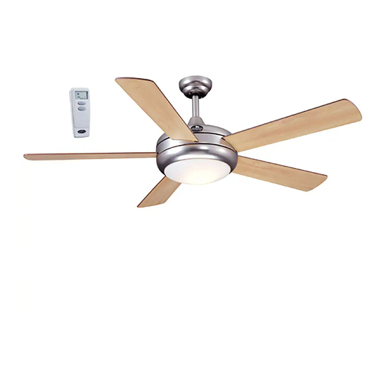
AERO CEILING FAN
MODEL #E-AER52BRZ5LKRCI
Lowes.com/harborbreeze
1
ITEM #0276094
Español p. 20
LISTED
E206035
Publicidad
Capítulos
Tabla de contenido
Solución de problemas

Manuales relacionados para Harbor Breeze E-AER52BRZ5LKRCI


Resumen de contenidos para Harbor Breeze E-AER52BRZ5LKRCI
- Página 1 ITEM #0276094 AERO CEILING FAN MODEL #E-AER52BRZ5LKRCI Español p. 20 Harbor Breeze® is a registered trademark of LF, LLC. All Rights Reserved. LOW MED HIGH Federal regulations require ceiling fans with light kits manufactured or imported after January 1, 2009, to limit total wattage consumed by the light kit to 190W. Therefore, this fan is equipped with a wattage limiting device.
-
Página 2: Tabla De Contenido
TABLE OF CONTENTS Safety Information .......................2 Package Contents .......................4 Hardware Contents ..........................5 Preparation ..........................5 Initial Installation ........................6 Fan Mounting ........................8 Wiring ..........................11 Final Installation ......................... 1 3 Automated Learning Process/Activating Code ..............14 Operating Instructions......................15 Care and Maintenance ......................17 Troubleshooting........................17 Limited Lifetime Warranty ....................18 Replacement Parts List .....................19 SAFETY INFORMATION READ AND SAVE THESE INSTRUCTIONS... - Página 3 SAFETY INFORMATION WARNING To reduce the risk of fire, electrical shock or personal injury, mount fan to outlet box marked "ACCEPTABLE FOR FAN SUPPORT OF 35 LBS. (15.9 KG) OR LESS" and use mounting screws provided with the outlet box. Most outlet boxes commonly used for the support of lighting fixtures are not acceptable for fan support and may need to be replaced.
-
Página 4: Package Contents
PACKAGE CONTENTS LOW MED HIGH PART DESCRIPTION QUANTITY PART DESCRIPTION QUANTITY Canopy Mounting Screw Downrod (preassembled) Canopy Pin (preassembled) Mounting Bracket Clip (preassembled) Motor Housing Glass Shade Yoke Cover Star Washer Blade (preassembled) Remote Control Transmitter Remote Control Receiver Battery Motor Screw IMPORTANT REMINDER: You must use the (preassembled) -
Página 5: Hardware Contents
HARDWARE CONTENTS (shown actual size) Blade Fiber Screw Blade E3 Wire Washer Connector Qty. 15 + 1 extra Qty. 15 Qty. 6 + 1 extra + 4 extra PREPARATION Before beginning assembly of product, make sure all parts are present. Compare parts with package contents list and hardware contents list. -
Página 6: Initial Installation
INITIAL INSTALLATION Turn off circuit breakers and wall switch to the fan supply line leads. DANGER: Failure to disconnect power supply prior to installation may result in serious injury or death. Determine mounting method to use. A. Standard mount B. Angle mount IMPORTANT: If using the angle mount, ensure the ceiling angle is not steeper than 19°. -
Página 7: Important
INITIAL INSTALLATION 4a. Loosen canopy mounting screws (L) in slotted holes of canopy (B) and remove the other two canopy mounting screws (L) and star washers (P) save for later use. Remove mounting bracket (C) from canopy (B). Secure mounting bracket (C) to outlet box (not included) using screws, spring washers and flat STANDARD ANGLE... -
Página 8: Fan Mounting
FAN MOUNTING Lift the preassembled yoke plate and the top of motor housing (D) from motor and set aside. Yoke Plate Insert the blade (F) through the slot on the band on the motor housing (D). Align holes in blade (F) with holes inside motor. - Página 9 FAN MOUNTING Remove pin (M) and clip (N) from yoke at the top of motor housing (D) and partially loosen Screws and Nuts preassembled set screws and nuts. Yoke 5. Insert downrod (A) through canopy (B) and yoke cover (E). Thread wires from motor housing (D) through downrod (A).
- Página 10 FAN MOUNTNG Depending on the length of downrod you use, you may need to cut the lead wires back to simplify the wiring. If you decide to cut back the lead wires, it is 8 in. suggested you do so in the following manner: Take the lead wires and make sure you have pulled them all the way through the top of the downrod.
-
Página 11: Wiring
WIRING WARNING: To reduce the risk of fire, electrical shock, or personal injury, wire connectors provided with this fan are designed to accept only one 12-gauge house wire and two lead wires from the fan. If your house wire is larger than 12-gauge or there is more than one house wire to connect to the corresponding fan lead wires, consult an electrician for the proper size wire connectors to use. - Página 12 WIRING Wrap electrical tape (not included) around each individual wire connector (CC) down to the wire. WARNING: Make sure no bare wire or wire strands are visible after making connections. Place green and white connections on opposite side of box from the BLACK and BLUE (if applicable) connections.
-
Página 13: Final Installation
FINAL INSTALLATION 1. Lift canopy (B) to mounting bracket (C) and align slotted holes in canopy (B) with loosened canopy mounting screws (L) in mounting bracket (C). Twist canopy (B) to lock, then insert the two canopy mounting screws (L) and star washers (P) previously removed (Step 4a, page 7). -
Página 14: Automated Learning Process/Activating Code
AUTOMATED LEARNING PROCESS/ACTIVATING CODE CAUTION: The remote control transmitter (G) can be programmed to multiple receivers or fans. If this is not desired, turn wall switch off to any other programmable receiver or fan. Remove battery cover from back of remote control transmitter (G). -
Página 15: Operating Instructions
AUTOMATED LEARNING PROCESS/ACTIVATING CODE Modifications not approved by the party responsible for compliance could void the user's authority to operate the equipment. *NOTE: This equipment has been tested and found to comply with the limits for a Class B digital device, pursuant to Part 15 of the FCC Rules. - Página 16 OPERATING INSTRUCTIONS 2. Use the fan reverse switch, located on top of the motor housing (D), to optimize the fan for seasonal performance. A ceiling fan will allow you to raise your thermostat setting in summer and lower your thermostat setting in winter without feeling a difference in your comfort.
-
Página 17: Care And Maintenance
CARE AND MAINTENANCE At least twice each year, lower canopy (B) to check downrod (A) assembly, and then tighten all screws on the fan. Clean motor housing (D) with only a soft brush or lint-free cloth to avoid scratching the finish. Clean blades (F) with a lint-free cloth. You may occasionally apply a light coat of furniture polish to wood blades for added protection. -
Página 18: Limited Lifetime Warranty
TROUBLESHOOTING PROBLEM POSSIBLE CAUSE CORRECTIVE ACTION Fan operates but 1. Bulb not installed correctly. 1. Re-install bulb. light fails (if 2. Wires in canopy not wired 2. Check wires in canopy and, applicable). properly. if necessary, re-wire according to instructions on pages 11 and 3. -
Página 19: Replacement Parts List
Lock Washer 276094-K Canopy Mounting Screw 276094-L 276094-M Clip 276094-N Glass Shade 276094-O Star Washer 276094-P Blade Screw 276094-AA Fiber Blade Washer 276094-BB Printed in China Harbor Breeze® is a registered trademark of LF, LLC. All Rights Reserved. Lowes.com/harborbreeze NOLI1410... - Página 20 EXPLODED VIEW/ VISTA DETALLADA LOW MED HIGH...
- Página 21 Quick Reference Guide Guía de referencia rápida BEFORE BEGINNING INSTALLATION/ ANTES DE COMENZAR LA INSTALACIÓN This is a general overview of assembly process. Read the complete installation manual for detailed instructions and safety information./Este es un resumen general del proceso de ensamblaje. Lea el manual de instalación completo para obtener instrucciones detalladas e información de seguridad.
-
Página 22: Installation Overview
INSTALLATION OVERVIEW/ DESCRIPCIÓN GENERAL DE LA INSTALACIÓN Turn Off Power Source Turn Off Power Source Turn Off Power Source Turn Off Power Source Install Mounting Bracket Apague la fuente de alimentación Turn off power source Turn off power source Turn off power source Turn off power source Instale el soporte de montaje STANDARD... -
Página 23: Installation Overview/ Descripción General De La Instalación
INSTALLATION OVERVIEW/ DESCRIPCIÓN GENERAL DE LA INSTALACIÓN Install Blades Remove Top of Motor Housing 8 8 6 Fije las aspas Quite la parte superior de la carcasa del motor See Page See Page See Page See Page Consulte la Consulte la See Page See Page página... -
Página 24: Adjunte Su Recibo Aquí
ARTÍCULO #0276094 VENTILADOR DE TECHO AERO MODELO #E-AER52BRZ5LKRCI Harbor Breeze ® es una marca registrada de LF, LLC. Todos los derechos reservados. BAJO MEDIO ALTO Los reglamentos federales requieren que los ventiladores de techo con kit de iluminación fabricados o importados después del 1 de enero de 2009, tengan un límite de vataje total consumido por el kit de iluminación de 190 vatios. - Página 25 ÍNDICE Información de seguridad ......................21 Contenido del paquete ......................23 Aditamentos ..........................24 Preparación ...........................24 Instalación inicial ........................25 Montaje del ventilador ......................27 Cableado ..........................30 Instalación final ........................32 Proceso de aprendizaje automatizado/código de activación ..........33 Instrucciones de funcionamiento ...................34 Cuidado y mantenimiento .....................36 Solución de problemas ......................36 Garantía limitada de por vida ....................37 Lista de piezas de repuesto....................38...
-
Página 26: Información De Seguridad
INFORMACIÓN DE SEGURIDAD ADVERTENCIA Para reducir el riesgo de incendio, descargas eléctricas o lesiones personales, monte el ventilador en una caja de salida marcada como "ACCEPTABLE FOR FAN SUPPORT OF 5 LBS. 35 LBS (15,9 KG) OR LESS" (APTA PARA SOSTENER VENTILADORES DE 15,88 KG (35 LBS) O MENOS) y utilice los tornillos de montaje que se proporcionan con la caja de salida. -
Página 27: Contenido Del Paquete
CONTENIDO DEL PAQUETE LOW MED HIGH PIEZA DESCRIPCIÓN CANTIDAD PIEZA DESCRIPCIÓN CANTIDAD Tornillo de montaje de la base Varilla (preensamblado) Base Pasador (preensamblado) Abrazadera de montaje Sujetador (preensamblado) Carcasa del motor Pantalla de vidrio Cubierta de la horquilla Aspa Arandela de estrella (preensamblado) Transmisor para control remoto Batería... -
Página 28: Aditamentos
ADITAMENTOS (se muestran en tamaño real) Tornillo Arandela para aspa para aspa Conector de de fibra cables E3 Cant. 15 + 1 adicional Cant. 15 Cant. 6 + 1 adicional + 4 adicional PREPARACIÓN Antes de comenzar a ensamblar el producto, asegúrese de tener todas las piezas. Compare las piezas con la lista del contenido del paquete y la lista de aditamentos. -
Página 29: Instalación Inicial
INSTALACIÓN INICIAL Interrumpa el suministro de energía del ventilador apagando los interruptores de circuito y el interruptor de pared. PELIGRO: Si no interrumpe el suministro de electricidad antes de la instalación, pueden producirse lesiones graves o la muerte. Determine el método de instalación que utilizará. A. -
Página 30: Importante
INSTALACIÓN INICIAL 4a. Afloje los tornillos de montaje (L) de la base en los orificios ranurados de la base (B) y retire los otros dos tornillos de montaje (L) de la base y las arandelas de estrella (P); conserve los tornillos de montaje (L) de la base y las arandelas de montaje (P) para usarlos posteriormente. -
Página 31: Montaje Del Ventilador
MONTAJE DEL VENTILADOR Levante la placa de la horquilla preensamblada y la parte superior de la carcasa del motor (D) del motor y déjelas a un lado. Placa de la horquilla Inserte el aspa (F) en la ranura de la banda de la carcasa del motor (D). - Página 32 MONTAJE DEL VENTILADOR Retire el pasador (M) y el sujetador (N) Tornillos de de la horquilla en la parte superior del bastidor del fijación y motor (D) y afloje parcialmente los tornillos de fijación y tuercas las tuercas preensambladas. Horquilla 5.
- Página 33 MONTAJE DEL VENTILADOR Según el largo de la varilla que utilice, es posible que necesite cortar los cables conductores para simplificar el cableado. Si decide cortar los cables 20,32 cm conductores, se sugiere hacerlo de la siguiente manera: Sujete los cables conductores y asegúrese de Bola jalarlos completamente a través de la parte superior de la varilla.
-
Página 34: Cableado
CABLEADO ADVERTENCIA: Para reducir el riesgo de incendios, descargas eléctricas o lesiones personales, los conectores de cables proporcionados con este ventilador están diseñados para soportar solo un cable de la casa de calibre 12 y dos cables conductores del ventilador. Si el conductor de la casa es de un calibre superior a 12 o hay más de un conductor de la casa para conectar a los cables conductores del ventilador correspondientes, consulte a un electricista cuál es el tamaño adecuado de los conectores de cables que debe utilizar. - Página 35 CABLEADO Cubra con cinta aislante (no se incluye) cada conector de cables (CC) individual hacia abajo del cable. ADVERTENCIA: Asegúrese de que no haya conductores desnudos ni filamentos de conductores visibles después de hacer la conexión. Coloque las conexiones verdes y blancas en el lado opuesto de las conexiones negras y azules de la caja (si corresponde).
-
Página 36: Instalación Final
INSTALACIÓN FINAL 1. Levante la base (B) hacia el soporte de montaje (C) y alinee los orificios ranurados en la base (B) con los tornillos de montaje de la base (L) aflojados del soporte de montaje (C). Gire la base (B) para asegurarla, luego inserte los dos tornillos de montaje (L) de la base y las arandelas de estrella (P) que retiró... -
Página 37: Proceso De Aprendizaje Automatizado/Código De Activación
PROCESO DE APRENDIZAJE AUTOMATIZADO/CÓDIGO DE ACTIVACIÓN PRECAUCIÓN: El transmisor del control remoto (G) se puede programar para varios receptores o ventiladores. Si usted no desea hacer esto, desactive el interruptor de pared para cualquier otro receptor o ventilador programable. Retire la cubierta de la batería de la parte posterior del transmisor del control remoto (G). -
Página 38: Instrucciones De Funcionamiento
PROCESO DE APRENDIZAJE AUTOMATIZADO/CÓDIGO DE ACTIVACIÓN Las modificaciones que no estén aprobadas por la parte responsable del cumplimiento podrían anular la autorización del usuario para utilizar el equipo. *NOTA: Este equipo ha sido probado y se ha verificado que cumple los límites para un dispositivo digital clase B, conforme a la sección 15 de las reglas de la FCC. - Página 39 INSTRUCCIONES DE FUNCIONAMIENTO 2. Utilice el interruptor de reversa del ventilador, ubicado en la parte superior de la carcasa del motor (D), para optimizar el rendimiento del ventilador según la estación del año. Un ventilador de techo le permitirá elevar la configuración de su termostato en verano y disminuirla en invierno, sin sentir una diferencia en su comodidad.
-
Página 40: Cuidado Y Mantenimiento
CUIDADO Y MANTENIMIENTO Al menos dos veces al año, baje la base (B) para revisar en ensamble de la varilla (A) y luego apriete todos los tornillos en el ventilador. Limpie la carcasa del motor (D) solo con un cepillo suave o un paño que no produzca pelusas para evitar rayar el acabado. -
Página 41: Garantía Limitada De Por Vida
SOLUCIÓN DE PROBLEMAS PROBLEMA CAUSA POSIBLE ACCIÓN CORRECTIVA El ventilador 1. La bombilla no está instalada 1. Vuelva a instalar la bombilla. funciona, pero la luz correctamente. no (si corresponde). 2. Los conductores de la base no están 2. Revise los conductores de la bien conectados. -
Página 42: Lista De Piezas De Repuesto
Pasador 276094-N Sujetador 276094-O Pantalla de vidrio 276094-P Arandela de estrella 276094-AA Tornillo para aspa 276094-BB Arandela para aspa de fibra Impreso en China ® Harbor Breeze es una marca registrada de LF, LLC. Todos los derechos reservados. Lowes.com/harborbreeze NOLI1410...