Tabla de contenido
Publicidad
Idiomas disponibles
Idiomas disponibles
Enlaces rápidos
Harbor Breeze® is a registered trademark
of LF, LLC. All Rights Reserved.
Federal regulations require ceiling fans with light kits manufactured or imported after
January 1, 2009, to limit total wattage consumed by the light kit to 190W. Therefore,
this fan is equipped with a wattage limiting device. If you lamp this fan's light kit with
bulbs totaling more than 190W, the wattage limiting device will reduce the watts
consumed to 190W.
ATTACH YOUR RECEIPT HERE
Serial Number
Questions, problems, missing parts? Before returning to your retailer, call or contact our
customer service department at 1-800-527-1292, 8:30 a.m. - 5:00 p.m., CST, Monday - Friday.
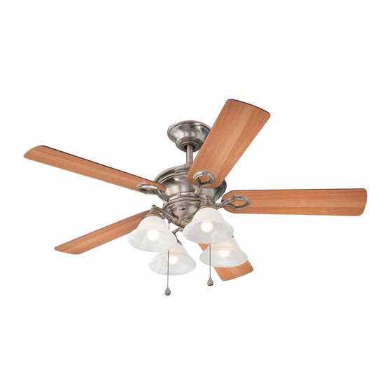
BELLHAVEN II CEILING FAN
Purchase Date
1
ITEM #18039
MODEL #E-BLHII52VPW5C4S
español p. 20
E192641
Publicidad
Capítulos
Tabla de contenido

Manuales relacionados para Harbor Breeze E-BLHII52VPW5C4S


Resumen de contenidos para Harbor Breeze E-BLHII52VPW5C4S
- Página 1 ITEM #18039 BELLHAVEN II CEILING FAN MODEL #E-BLHII52VPW5C4S Harbor Breeze® is a registered trademark español p. 20 of LF, LLC. All Rights Reserved. Federal regulations require ceiling fans with light kits manufactured or imported after January 1, 2009, to limit total wattage consumed by the light kit to 190W. Therefore, this fan is equipped with a wattage limiting device.
-
Página 2: Tabla De Contenido
TABLE OF CONTENTS Safety Information ………………………………………………………...……..…....2 - 3 Package Contents ……………………………………………………..……..…..…....4 Hardware Contents ........................5 Preparation ..….…………………..……………………….…………….……………....5 Initial Installation ..……………………...…………………………………………..6 - 7 Fan Mounting ..…………………………………………………........7 - 9 Wiring ....……………………..........………....9 - 11 Final Installation …………….……………………….…………….……....…....11 - 14 Operation Instructions .......…………………………........15 - 16 Care and Maintenance ……………………………………………………………..……………..16 Troubleshooting ..………...………………………….……………..………......17 - 18... -
Página 3: Safety Information
SAFETY INFORMATION WARNINGS To reduce the risk of fire, electrical shock, or personal injury, mount fan to outlet box marked "ACCEPTABLE FOR FAN SUPPORT OF 35 LBS (15.9 KG) OR LESS" and use mounting screws provided with the outlet box. Most outlet boxes commonly used for the support of lighting fixtures are not acceptable for fan support and may need to be replaced. -
Página 4: Package Contents
PACKAGE CONTENTS PART DESCRIPTION QUANTITY PART DESCRIPTION QUANTITY Canopy Mounting Screw Downrod (preassembled) Canopy Pin (preassembled) Mounting Bracket Clip (preassembled Motor Housing Pull Chain Extension Fitter Plate Socket Ring Yoke Cover (preassembled) Light Kit Fitter Finial (preassembled) Blade Arm Candelabra Base Bulb Blade Canopy Cover Glass Shade... -
Página 5: Hardware Contents
HARDWARE CONTENTS (shown actual size) Blade Fiber Screw Blade Washer E3 Wire Qty. 15 Connector Qty. 15 Qty. 4 PREPARATION Before beginning assembly of product, make sure all parts are present. Compare parts with package contents list and hardware contents above. If any part is missing or damaged, do not attempt to assemble the product. -
Página 6: Initial Installation
INITIAL INSTALLATION Turn off circuit breakers and wall switch to the fan supply line leads. (Fig. 1) DANGER: Failure to disconnect power supply prior to installation may result in serious injury or death. Determine mounting method to use. (Fig. 2) A. -
Página 7: Important
INITIAL INSTALLATION Secure mounting bracket (C) to outlet box using screws, spring washers, and flat washers provided with the outlet box. (Fig. 4) *NOTE: It is very important that you use the proper hardware when installing the mounting bracket (C) as this will support the fan. IMPORTANT: If using the angle mount, make sure open end of mounting bracket (C) is installed facing the higher point of the ceiling. - Página 8 FAN MOUNTING Insert downrod (A) through canopy (B), canopy cover (T), and yoke cover (F). [Note: Canopy cover (T) must be turned with the shiny side toward the motor housing (D).] Thread wires from motor housing (D) through downrod (A). (Fig.
-
Página 9: Wiring
FAN MOUNTING If you decided to cut back the lead wires in Step 4, strip 1/2 in. of insulation from end of white wire. Twist stripped ends of each strand of wire within the insulation with pliers (not included). (Fig. 5) Repeat Step 5 for black, blue (if applicable) and green wires. - Página 10 WIRING Choose wiring diagram (Fig. 1A, Fig. 1B or Fig. FAN AND LIGHT CONTROLLED BY PULL CHAINS 1C) that fits your situation and make appropriate wiring connections as follows: [NOTE: For each BLACK wire connection below, use one of the wire WHITE 120 V Power FROM...
-
Página 11: Final Installation
WIRING Wrap electrical tape (not included) around each individual wire connector (CC) down to the wire as shown in Fig. 2. WARNING: Make sure no bare wire or wire strands are visible after making connections. Place green and white connections on opposite side of box from the black and blue (if applicable) connections. - Página 12 FINAL INSTALLATION Partially insert three blade screws (AA), along with three fiber blade washers (BB), to attach one blade arm (H) to a blade (I). Then, tighten each blade screw (AA) starting with the one in the middle. (Fig. 2) Repeat with remaining blades (I). Hardware Used Blade Screw Fiber Blade Washer...
- Página 13 FINAL INSTALLATION Remove finial (R) from threaded rod on fitter plate (E). (Fig. 5) Save finial (R) for later use. Connect male plug from motor housing (D) to female plug from light kit fitter (G), matching up the colors on the male plug with the colors on the female plug for correct fit.
- Página 14 FINAL INSTALLATION Remove socket rings (Q) from sockets. Attach glass shades (J) with socket rings (Q). (Fig. 8) Note: Do not overtighten socket rings (Q) as glass may crack or break. Install four candelabra base 40-watt max. bulbs (S) included. (Fig. 9) Important: When you need to replace bulbs, please allow bulb(s) and glass shade(s) to cool down before touching them.
-
Página 15: Operation Instructions
OPERATION INSTRUCTIONS The pull chain labeled SPEED has four positions to control fan speed. One pull is HIGH, two is MEDIUM, three is LOW and four turns the fan OFF. (Fig. 1) 2. The pull chain labeled LIGHT is used to turn the lights ON or OFF. -
Página 16: Care And Maintenance
OPERATION INSTRUCTIONS 3A. In warmer weather, setting the reverse switch in the LEFT position will result in downward airflow creating a wind chill effect. (Fig. 3A) 3B. In cooler weather, setting the reverse switch in the RIGHT position will result in upward airflow that can help move stagnant, hot air off the ceiling area. -
Página 17: Troubleshooting
TROUBLESHOOTING If you have any questions regarding the product, please call customer service at 1-800-527-1292, 8:30 a.m. - 5 p.m., CST, Monday - Friday Warning: Before beginning work, shut off the power supply to avoid electrical shock. PROBLEM POSSIBLE CAUSE CORRECTIVE ACTION Fan does not move. -
Página 18: Warranty
TROUBLESHOOTING PROBLEM POSSIBLE CAUSE CORRECTIVE ACTION Lights dim when turning 1. No action necessary--fan will 1. Fan is lamped with more than automatically re-set within 5 190W and fan was turned off at fan and/or lights on. wall switch, causing the wattage seconds after turning wall switch back on. -
Página 19: Replacement Parts List
REPLACEMENT PARTS LIST For replacement parts, call our customer service department at 1-800-527-1292, 8:30 a.m. - 5:00 p.m., CST, Monday - Friday. When ordering parts, please have the Model # or Item # of the fan available, which can be found on page 1. PART DESCRIPTION Downrod... -
Página 20: Ventilador De Techo Bellhaven
ARTICULO #18039 VENTILADOR DE TECHO BELLHAVEN II MODELO #E-BLHII52VPW5C4S Harbor Breeze® es marca registrada de LF, LLC. Reservados todos los derechos. El reglamento federal requiere que un ventilador de techo con juego de luz fabricado o importado después del 1 de enero del 2009 limite el vatiaje total que consume el juego de luz a 190W. -
Página 21: Indice De Materias
INDICE DE MATERIAS Información de seguridad …………………………………......……...……..21 - 22 Contenido del paquete …………………………………………………………………..……..23 Contenido de artículos de ferretería ..................24 Preparación ....….…………………..……………………….…………….…..…..24 Instalación inicial .....…………………………………………………………..25 - 26 Montaje del ventilador ....................26 - 28 Conexión de los cables ………………………………………..…………....28 - 31 Instalación final ….…………….…….………………….……...…….……......31 - 34 Instrucciones de funcionamiento... - Página 22 INFORMACION DE SEGURIDAD ADVERTENCIAS Para reducir el riesgo de incendio, choque eléctrico o daño corporal, sujete el ventilador a una caja de salida marcada "Aceptable para sostener ventilador" ("ACCEPTABLE FOR FAN SUPPORT" en inglés) y use los tornillos de montaje proporcionados con la caja de salida.
-
Página 23: Contenido Del Paquete
CONTENIDO DEL PAQUETE PIEZA DESCRIPCION CANTIDAD PIEZA DESCRIPCON CANTIDAD Tornillo para montaje de la Vástago cubierta (preensamblado) Cubierta Clavija (preensamblada) Soporte de montaje Sujetador (preensamblado) Bastidor del motor Extensión para la cadena Placa de conexión de encendido Cubierta del yugo Anillo de portalámpara Conectador para el juego (preensamblado) -
Página 24: Contenido De Artículos De Ferretería
CONTENIDO DE ARTICULOS DE FERRETERIA (se muestra en tamaño natural) Tornillo Arandela para la de fibra paleta para la Conector paleta para cable Ctd. 15 Ctd. 15 Ctd. 4 PREPARACION Antes de empezar con el ensamblaje del producto, asegúrese de tener todas las piezas. Compare las piezas con la lista del contenido de piezas y el contenido de artículos de ferretería más arriba. -
Página 25: Instalación Inicial
INSTALACION INICIAL Apague los interruptores de circuito y el interruptor de pared para interrumpir el suministro de energía del ventilador. (Fig. 1) PELIGRO: Si no interrumpe el suministro de electricidad antes de la instalación, pueden producirse lesiones graves o la muerte. Determine el método de instalación que utilizará. -
Página 26: Importante
INSTALACION INICIAL Asegure el soporte de montaje (C) a la caja de salida con los tornillos, las arandelas de resorte y las arandelas planas que incluye la caja de salida. (Fig. 4) *NOTA: Es muy importante que use los aditamentos adecuados para instalar el soporte de montaje (C), ya que éste sostendrá... - Página 27 MONTAJE DEL VENTILADOR Introduzca el vástago (A) en la cubierta (B), la decoración para la cubierta (T), y la cubierta del yugo (F). [Nota: Se tiene que voltear la decoración para la cubierta (T) para que el lado brillante dé al bastidor del motor (D).] Pase los cables del bastidor del motor (D) por el vástago (A).
-
Página 28: Conexión De Los Cables
MONTAJE DEL VENTILADOR Si decide por cortar los cables principales en el paso 4, pele 1,5 cm de material aislante del extremo del cable blanco. Retuerza los extremos pelados de cada filamento dentro del material aislante con alicate (no incluido). (Fig. 5) Repita el paso 5 para los cables negros, azules (si aplica) y verdes. -
Página 29: Ventilador Y Luz Controlados Por Cadenas De Tiro
CONEXION DE LOS CABLES Escoja el diagrama de cableado (Fig. 1A, Fig. 1B o Fig. 1C) que se ajuste a su situación y realice las conexiones del cableado adecuadas como se indica a continuación: [NOTA: Para cada conexión de cables a continuación, utilice uno de los conectores de cables (CC) provistos, asegurándose de atornillar el conector de cable (CC) en dirección de las manecillas del reloj]. - Página 30 CONEXION DE LOS CABLES 1C. VENTILADOR Y LUZ CONTROLADOS VENTILADOR Y LUZ CONTROLADOS POR DOS POR DOS INTERRUPTORES DE PARED: INTERRUPTORES DE PARED Si desea controlar el ventilador y la luz con NEGRO (INTERRUPTOR DE PARED) interruptores de pared separados, conecte NEGRO (INTERRUPTOR DE PARED PARA LA LUZ) el conductor NEGRO del ventilador al Alimentación...
-
Página 31: Instalación Final
CONEXION DE LOS CABLES IMPORTANTE: El uso de un regulador de intensidad de rango completo (no se incluye) para controlar la velocidad del ventilador provocará un zumbido intenso del ventilador. Para reducir el riesgo de incendios o descargas eléctricas, NO use un regulador de intensidad de rango completo para controlar la velocidad del ventilador. - Página 32 INSTALACION FINAL Parcialmente introduzca tres tornillos para la paleta (AA), junto con tres arandelas de fibra para la paleta (BB), para sujetar un brazo para la paleta (H) a una paleta (I). Luego, apriete cada tornillo para la paleta (AA), empezando con el de en medio. (Fig. 2) Repita esto con las demás paletas (I).
- Página 33 INSTALACION FINAL Quite el adorno con rosca (R) de la varilla roscada en la placa de conexión (E). (Fig. 5) Guarde el adorno con rosca (R) para uso más adelante. Conecte el enchufe macho del bastidor del motor (D) al enchufe hembra del conectador para el juego de luz (G), haciendo coincidir los colores en el enchufe macho con los del enchufe hembra para que se conecten...
- Página 34 INSTALACION FINAL Quite los anillos del portalámpara (Q) de los portalámparas. Sujete las pantallas de vidrio (J) con los anillos del portalámpara (Q). (Fig. 8) Nota: No apriete los anillos del portalámpara (Q) demasiado porque el vidrio se puede rajar o romper.
-
Página 35: Instrucciones De Funcionamiento
INSTRUCCIONES DE FUNCIONAMIENTO La cadena de encendido etiquetada VELOCIDAD tiene cuatro posiciones para controlar la velocidad del ventilador. Jálela una vez para la velocidad ALTA, dos veces para la velocidad MEDIA, tres veces para la velocidad BAJA y cuatro veces para APAGAR el ventilador. -
Página 36: Cuidado Y Mantenimiento
INSTRUCCIONES DE FUNCIONAMIENTO 3A. En climas más cálidos, la configuración del interruptor de reversa en la posición a la IZQUIERDA creará un flujo de aire descendente que generará un efecto de viento refrescante. (Fig. 3A) 3B. En climas más fríos, la configuración del interruptor de reversa en la posición a la DERECHA creará... -
Página 37: Localización De Fallas
LOCALIZACION DE FALLAS Si tiene alguna pregunta acerca del producto, por favor llame al servicio al cliente al 1-800-527-1292, de 8:30 a.m. a 5:00 p.m., hora central, de lunes a viernes. ADVERTENCIA: Antes de proseguir, desconecte la electricidad, quitando los fusibles o cortando el suministro de energía de los circuitos para evitar un choque eléctrico. - Página 38 LOCALIZACION DE FALLAS PROBLEMA CAUSA POSIBLE ACCIÓN CORRECTIVA 2. Verifique que se conectaron bien 2. No se conectaron correctamente los los cables en la caja de salida y, cables en la caja de salida. si es necesario, vuelva a conectarlos según las instrucciones en las páginas 29 y Asegúrese de que el interruptor 3.
-
Página 39: Garantía
GARANTIA GARANTIA LIMITADA DE POR VIDA: Litex Industries garantiza que este ventilador está libre de defectos de mano de obra y de materiales desde la fecha de salida de la fábrica por el tiempo de por vida limitada a partir de la fecha de compra. Esta garantía sólo se aplica al comprador original. Litex Industries se compromete a corregir cualquier defecto libre de cargo o, si lo considera necesario, a reemplazar el ventilador por un modelo equiparable o superior. -
Página 40: Lista De Piezas De Repuestos
LISTA DE PIEZAS DE REPUESTOS Para piezas de repuesto, llame a nuestro departamento de servicio al cliente al 1-800-527-1292, de 8:30 a.m. a 5:00 p.m., hora central, de lunes a viernes. Al pedir piezas, por favor tenga listo el No. de modelo o No.