Tabla de contenido
Publicidad
Idiomas disponibles
Idiomas disponibles
Enlaces rápidos
¡IMPORTANTE!
IMPORTANT!
NO DESTRUIR
DO NOT DESTROY
Installation
Manual
and
de Instalación
Maintenance
y
Manual
Mantenimiento
con Información sobre Seguridad
with Safety Information
y Lista de Refacciones
and Parts List
LAS REFACCIONES RECOMENDADAS SE RESALTAN EN GRIS
RECOMMENDED SPARE PARTS HIGHLIGHTED IN GRAY
Effective August 2021
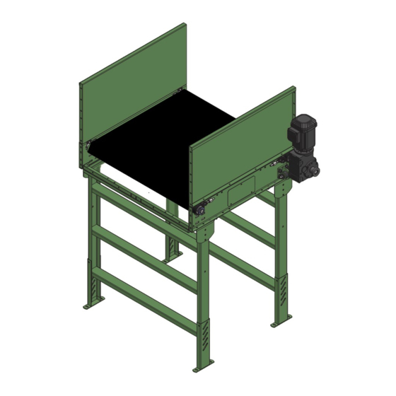
Model HSQ
Bulletin #743
HYTROL | Jonesboro, Arkansas
Copyright © 1947–2021 Hytrol. All rights reserved.
1
Publicidad
Capítulos
Tabla de contenido
Solución de problemas

Resumen de contenidos para HYTROL HSQ
- Página 1 Safety Information y Lista de Refacciones and Parts List LAS REFACCIONES RECOMENDADAS SE RESALTAN EN GRIS RECOMMENDED SPARE PARTS HIGHLIGHTED IN GRAY Effective August 2021 Model HSQ Bulletin #743 HYTROL | Jonesboro, Arkansas Copyright © 1947–2021 Hytrol. All rights reserved.
-
Página 2: Tabla De Contenido
Conveyor Start-Up . . . . . . . . . . . . . . . . . . . . . . . . .6 1 . Contact Dealer from whom conveyor was purchased or nearest HYTROL Integration Partner . -
Página 3: Safety Information
. In an effort to reduce the possibility of injury to personnel working around HYTROL conveying equipment, safety labels are placed at Where employee safety is dependent upon stopping and/or various points on the equipment to alert them of potential hazards . -
Página 4: Support Installation
INSTALLATION • Support Installation 1 . Determine primary direction of product flow . Figure 5A indicates the preferred flow as related to the drive . 2 . Refer to “Match-Mark” numbers on ends of conveyor sections . Position them in sequence near the area of installation . 3 . - Página 5 • Belt Installation BELT INSTALLATION—END DRIVE (INSTALACIÓN DE LA BANDA—UNIDAD MOTRIZ DE EXTREMO) FIGURE 5A DRIVE BELT (TOP SIDE) PULLEY (BANDA [LADO SUPERIOR]) (POLEA MOTRIZ) TAIL PULLEY (POLEA DE BELT FLOW RETORNO) (FLUJO DE BANDA) TAKE-UP BOLT (TORNILLO TENSOR) DIMENSION FIGURE 5B FIGURE 5C TAKE-UP BOLT...
-
Página 6: Operation
These instructions differ for units that contain Snub Rollers . 5D . The HSQ is not designed to run in reverse . 4 . Make sure belt lacing has been installed correctly and is square with the If belt continues to track improperly, re-check all items covered in “Pre- belt (Figure 5C) . -
Página 7: Troubleshooting
2) Low voltage to motor . 2) Have electrician check and correct as necessary . 3) Low lubricant level in reducer . 3) Relubricate per manufacturer’s recommendations . For HYTROL reducer, refer to Installation and Maintenance Manual #684 (Speed Reducers 4A, 4AC, 5A, 5AC) . -
Página 8: 4" End Drive & Parts List
• Model HSQ Parts Drawing & Parts List (4" End Drive) Dibujo de Partes y Lista de Partes del Modelo HSQ (Unidad Motriz de Extremo de 4") Ref. # Description 4'0" Side Channel Weld, Right Hand - Queue Drive 1/2-13" x 1-1/2" Carriage Bolt 4'0"... -
Página 9: 6" End Drive & Parts List
• Model HSQ Parts Drawing & Parts List (6" End Drive) Dibujo de Partes y Lista de Partes del Modelo HSQ (Unidad Motriz de Extremo de 6") Ref. # Description 4'0" Side Channel Weld, Right Hand - Queue Drive 1/2-13" x 1-1/2" Carriage Bolt 4'0"... -
Página 10: Spanish Version
Alineación de la correa ....14 con el socio de integración de HYTROL más cercano. Solución de problemas ....15 2. -
Página 11: Información De Seguridad
En un esfuerzo por reducir la posibilidad de lesiones del personal libre de obstrucciones que pudieran poner en peligro al personal. que trabaja alrededor del equipo transportador HYTROL, se colocan etiquetas de seguridad en varios puntos del equipo para alertar sobre D) Ninguna persona debe subirse al elemento transportador de cargas peligros potenciales. -
Página 12: Instalación Del Soporte
INSTALACIÓN • Instalación del soporte 1. Determine la dirección principal del flujo del producto. La Figura 13A indica el flujo preferido en relación con el accionamiento. 2. Consulte los números de “marca de referencia” en los extremos de las secciones del transportador. Colóquelos en secuencia cerca del área de instalación. 3. -
Página 13: Instalación De La Correa
• Instalación de la correa BELT INSTALLATION—END DRIVE (INSTALACIÓN DE LA BANDA—UNIDAD MOTRIZ DE EXTREMO) FIGURA 13A DRIVE BELT (TOP SIDE) PULLEY (BANDA [LADO SUPERIOR]) (POLEA MOTRIZ) TAIL PULLEY (POLEA DE BELT FLOW RETORNO) (FLUJO DE BANDA) TAKE-UP BOLT (TORNILLO TENSOR) DIMENSION FIGURA 13B FIGURA 13C... -
Página 14: Operación
4. Asegúrese de que el enlace de la correa se haya instalado correctamente y esté El modelo HSQ no está diseñado para funcionar en retroceso. cuadrado con la correa (Figura 13C). Si la correa sigue alineándose incorrectamente, vuelva a revisar todos los puntos 5. -
Página 15: Solución De Problemas
2) Disponga que un electricista realice una revisión y corrección según sea necesario. 3) Vuelva a lubricar de acuerdo con las recomendaciones del fabricante. Para el reductor HYTROL, consulte el Manual de instalación y mantenimiento n.º 684 (Reductores de velocidad 4A, 4AC, 5A, 5AC). La correa no se mueve, 1) El transportador está... -
Página 16: Planned Maintenance Checklist
• Planned Maintenance Checklist Note: Check Set Screws after the first 24 hours of operation . (Lista de Mantenimiento Preventivo) NOTA: Revise los tornillos después de las primeras 24 horas de operación. Schedule (Horario) Component Suggested Action (Componente) (Sugerencia) Weekly Monthly Quarterly (Semanal)


