Tabla de contenido
Publicidad
Enlaces rápidos
sauder.com
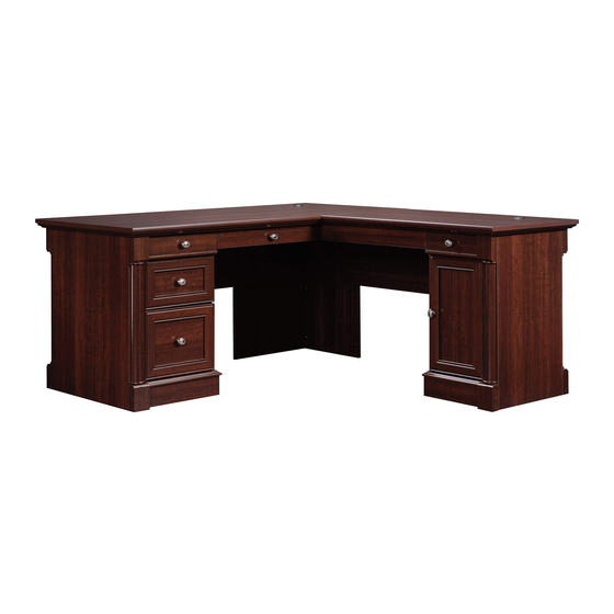
L-Shaped Desk
Palladia Collection | Model 413670
Need help? Visit Sauder.com to view video assembly tips or chat with a live rep.
Prefer the phone? Call 1-800-523-3987.
Share your journey!
The original desktop.
NOTE: THIS INSTRUCTION
BOOKLET CONTAINS IMPORTANT
SAFETY INFORMATION.
PLEASE READ AND KEEP FOR
FUTURE REFERENCE.
English pg 1-64
Français pg 65-72
Español pg 73-80
Lot # 511551
12/15/17
Purchased: __________________
Be sure to give us a ring before
making any returns. 1-800-523-3987
Publicidad
Tabla de contenido

Manuales relacionados para Sauder Palladia 413670


Resumen de contenidos para Sauder Palladia 413670
- Página 1 Palladia Collection | Model 413670 NOTE: THIS INSTRUCTION BOOKLET CONTAINS IMPORTANT SAFETY INFORMATION. Need help? Visit Sauder.com to view video assembly tips or chat with a live rep. PLEASE READ AND KEEP FOR FUTURE REFERENCE. Prefer the phone? Call 1-800-523-3987.
- Página 2 TOP RIGHT REAR MOLDING (1) RIGHT MODESTY PANEL (1) LEFT BACK SKIRT (2) PLINTH (8) LEFT MODESTY PANEL (1) KEYBOARD UPRIGHT (1) MMM HALF DISK (8) SPACER (2) KEYBOARD FRONT (1) END MOLDING (4) KEYBOARD BACK (1) Page 2 413670 www.sauder.com/services...
-
Página 3: Part Identifi Cation
Now you know Part Identifi cation our ABCs. www.sauder.com/services 413670 Page 3... - Página 4 RIGHT DRAWER SIDE (Top Left) (1) D708 FILE DRAWER BOTTOM (1) TOP RIGHT DRAWER BACK (1) LEFT DRAWER SIDE (Top Left) (1) DRAWER BOX FRONT (1) RIGHT DRAWER SIDE (Top Right) (1) D716 DRAWER BOTTOM (2) D958 D716 D211 D708 D716 Page 4 413670 www.sauder.com/services...
- Página 5 KNOB - 6 FELT DISC CARD - 1 LOCK - 1 LOCK COVER - 1 BRACKET - 1 GROMMET - 3 METAL PIN - 8 RUBBER SLEEVE - 4 GROMMET CAP - 3 CORD CLIP - 3 www.sauder.com/services 413670 Page 5...
-
Página 6: Tabla De Contenido
52S SILVER 3/4" PAN HEAD SCREW - 2 GOLD 1" MACHINE SCREW - 3 SILVER 9/16" LARGE HEAD SCREW - 2 SMALL BLACK 1-1/4" FLAT HEAD SCREW - 2 113S BLACK 1-15/16" FLAT HEAD SCREW - 12 Page 6 413670 www.sauder.com/services... - Página 7 Scan this QR code or go to this address: To begin assembly, fasten the KEYBOARD SIDES (YY and ZZ) å http://qr.sauder.com/?ID= 1966 to watch a video on how to assemble your unit. to the KEYBOARD SHELF (AAA). Use four BROWN 1-1/2" FLAT HEAD SCREWS (14S).
-
Página 8: Silver 5/8" Flat Head Screw
Fasten the KEYBOARD HINGES (12H) to the å KEYBOARD SHELF (AAA). Use two SILVER 9/16" LARGE HEAD SCREWS (54S). SILVER 5/8" FLAT HEAD SCREW SILVER 9/16" LARGE HEAD SCREW (4 used in this step) (2 used in this step) Page 8 413670 www.sauder.com/services... - Página 9 BROWN 1-1/2" FLAT HEAD SCREW (2 used for the #1 holes in the SLIDES) Open end GOLD 1" MACHINE SCREW (1 used for the KNOB) GOLD 5/16" FLAT HEAD SCREW (2 used for the fi rst holes in the SLIDES) www.sauder.com/services 413670 Page 9...
- Página 10 Be sure the grooves in each part line up with each other on the inside of the drawer. D716 Use top hole Groove D958 Groove BLACK 1-9/16" FLAT HEAD SCREW (12 used in this step) D211 D708 D211 Groove Page 10 413670 www.sauder.com/services...
-
Página 11: Black 9/16" Large Head Screw
Fasten the TOP DRAWER FRONTS (GG and LL) to the TOP å DRAWER FRONT BRACKETS (6G). Use four BLACK 9/16" LARGE HEAD SCREWS (1S). BLACK 9/16" LARGE HEAD SCREW (4 used in this step) Push down www.sauder.com/services 413670 Page 11... - Página 12 Fasten a KNOB (33K) to the TOP LEFT DRAWER FRONT (LL). Use a GOLD 1" MACHINE SCREW (50S). å BLACK 1-9/16" FLAT HEAD SCREW (2 used through hole #1) Open end Open end GOLD 1" MACHINE SCREW (1 used for the KNOB) GOLD 5/16" FLAT HEAD SCREW (2 used through hole #3) Page 12 413670 www.sauder.com/services...
- Página 13 Fasten a KNOB (33K) to the TOP RIGHT DRAWER FRONT (GG). Use a GOLD 1" MACHINE SCREW (50S). å GOLD 1" MACHINE SCREW (1 used for the KNOB) Open end Open end GOLD 5/16" FLAT HEAD SCREW (4 used for the SLIDES) www.sauder.com/services 413670 Page 13...
- Página 14 FRONTS (S and Z). Use eight BLACK 1-1/8" PAN HEAD SCREWS (9S). your screwdriver and hammer. Push down D211 These edges should be even. BLACK 1-1/8" PAN HEAD SCREW (8 used for the DRAWER FRONTS) These edges should be even. Page 14 413670 www.sauder.com/services...
-
Página 15: Silver 1-1/4" Machine Screw
BOX FRONT, through the DRAWER FRONT, and into the KNOB. Open end BLACK 1-9/16" FLAT HEAD SCREW (2 used through hole #1) Open end SILVER 1-1/4" MACHINE SCREW (1 used for the KNOB) GOLD 5/16" FLAT HEAD SCREW (2 used through hole #3) www.sauder.com/services 413670 Page 15... - Página 16 Push the black lever in and pull the SLIDE from the RAIL. Open end SILVER 1-1/4" MACHINE SCREW (1 used for the KNOB) D211 Open end GOLD 5/16" FLAT HEAD SCREW (4 used in this step) Page 16 413670 www.sauder.com/services...
-
Página 17: Brown 7/16" Large Head Screw
Fasten the LOCK BRACKET (5J) to the FILE DRAWER RIGHT SIDE (D211). Use a BROWN 7/16" LARGE HEAD SCREW (6S). å Insert the FILE RODS into the holes of your choice in the FILE GLIDES, depending on your fi le sizes. D211 BROWN 7/16" LARGE HEAD SCREW (1 used in this step) www.sauder.com/services 413670 Page 17... - Página 18 Step 12 Fasten the HINGES (14H) to the DOOR (P). Use four å BLACK 1/2" FLAT HEAD SCREWS (11S). BLACK 1/2" FLAT HEAD SCREW (4 used in this step) Page 18 413670 www.sauder.com/services...
- Página 19 Step 13 Push four SAUDER TWIST-LOCK® FASTENERS (7F) into the large holes in the å OUTER ENDS (A and C). Repeat this step for the INNER ENDS (B3 and D3), BOTTOMS (I2 and J2), å RIGHT MODESTY PANEL (K2), BACKS (N and O), LEGS (R and T), KEYBOARD UPRIGHT (VV), and both SPACERS (L4).
- Página 20 Open end GOLD 5/16" FLAT HEAD SCREW (12 used in this step) Open end Open end Open end When this NARROW EXTENSION RAIL (40NA) is fastened to the UPRIGHT (E2), it will hang over the edge. Page 20 413670 www.sauder.com/services...
- Página 21 RAIL out to fi nd the other holes that line up with the holes in the END and UPRIGHT. Turn a SCREW into this hole. GOLD 5/16" FLAT HEAD SCREW (4 used in this step) Open end Open end www.sauder.com/services 413670 Page 21...
-
Página 22: Brown 1" Flat Head Screw
Fasten the HALF DISKS (MMM) to the PLINTHS (JJJ). Use å eight BROWN 1" FLAT HEAD SCREWS (12S). Remember: Righty tighty. Lefty loosey. BROWN 1" FLAT HEAD SCREW (8 used in this step) The larger hole should be facing up. Page 22 413670 www.sauder.com/services... - Página 23 Fasten four PLINTHS (JJJ) to the OUTER ENDS (A and C). å Use eight BLACK 9/16" LARGE HEAD SCREWS (1S). (28 used) BLACK 9/16" LARGE HEAD SCREW (36 used in this step) Use bottom holes Use bottom holes www.sauder.com/services 413670 Page 23...
- Página 24 HALF DISKS (MMM) on the PLINTHS (JJJ). BLACK 9/16" LARGE HEAD SCREW (20 used in this step) Use bottom holes Use bottom holes The END MOLDINGS (M26) should be centered over the HALF DISKS (MMM). Page 24 413670 www.sauder.com/services...
- Página 25 PANEL (QQ). Then, insert the metal end of a CAM DOWEL (2F) into each HIDDEN CAM. Do not tighten the HIDDEN CAMS in this step. Arrow Arrow Insert the metal end of the CAM DOWEL into the HIDDEN CAM. www.sauder.com/services 413670 Page 25...
- Página 26 Tap fi ve MOLDING CONNECTORS (17F) into the notches in å the MOLDINGS (BBB, CCC, DDD, EEE, FFF, GGG, and HHH). Use your hammer to tap the MOLDING CONNECTORS (17F) into the notches in the MOLDINGS. Flat end Flat end Flat end Page 26 413670 www.sauder.com/services...
-
Página 27: Black 1-9/16" Flat Head Screw - 16 35S
NOTE: Do not overtighten the SCREWS into the TOP. å The large hole must be here. BLACK 1-1/4" FLAT HEAD SCREW (26 used in this step) Do not overtighten the SCREWS (7S). The large hole must be here. www.sauder.com/services 413670 Page 27... - Página 28 SIDE MOLDING (FFF) on the RIGHT TOP (G2). Tighten two TWIST-LOCK® FASTENERS. Fasten a SPACER (L4) to the OUTER RIGHT END (A). å How to use the SAUDER TWIST-LOCK ® FASTENER Tighten two TWIST-LOCK® FASTENERS. 1. Insert the dowel end of the FASTENER into the hole of the adjoining part.
-
Página 29: Black 1-15/16" Flat Head Screw
BLACK 1-15/16" FLAT HEAD SCREW (2 used in this step) ® i t h f a c - L O S u r I S T r f a I S T w i t - L O ® www.sauder.com/services 413670 Page 29... - Página 30 Fasten a SPACER (L4) to the OUTER LEFT END (C). å Tighten two TWIST-LOCK® FASTENERS. Surface with TWIST-LOCK® FASTENERS r f a I S T w i t - L O ® Large hole should be located here. Page 30 413670 www.sauder.com/services...
- Página 31 BLACK 1-15/16" FLAT HEAD SCREW (2 used in this step) w i t ® r f a - L O I S T r f a I S T w i t - L O ® www.sauder.com/services 413670 Page 31...
- Página 32 Keyboard Drawer on the right side of your Desk. KEYBOARD DRAWER ON RIGHT KEYBOARD DRAWER Follow steps 43-58 as shown below if you prefer the å Keyboard Drawer on the left side of your Desk. KEYBOARD DRAWER ON LEFT KEYBOARD DRAWER Page 32 413670 www.sauder.com/services...
- Página 33 Pull at the front and back edges, slowly working the FASTENERS out of the holes. Push the LEFT UPRIGHT (F2) onto the TWIST-LOCK® å FASTENERS (7F) in the LEFT TOP (H2) and LEFT BACK (O). Tighten four TWIST-LOCK® FASTENERS. These edges should be even. www.sauder.com/services 413670 Page 33...
- Página 34 Push two CORD CLIPS (9P) into the holes in the LEFT TOP (H2). å NOTE: The CORD CLIPS are used to manage your cords. å 113S BLACK 1-15/16" FLAT HEAD SCREW (2 used in this step) BLACK 9/16" LARGE HEAD SCREW (4 used for the CONNECTOR PLATE) Page 34 413670 www.sauder.com/services...
- Página 35 F A S I S T - L O C E R S T E N T E N ® E R S F A S BLACK 1-1/8" PAN HEAD SCREW (2 used in this step) www.sauder.com/services 413670 Page 35...
- Página 36 BOTTOM (J2). Use fi ve BLACK 9/16" LARGE HEAD SCREWS (1S) through the holes in the BRACKETS and into the holes in the LEFT BOTTOM. These edges should be even. BLACK 9/16" LARGE HEAD SCREW (14 used in this step) Page 36 413670 www.sauder.com/services...
- Página 37 Fasten the LEFT BACK SKIRTS (UU) to the å INNER LEFT END (D3), LEFT BOTTOM (J2), and LEFT SIDE SKIRT (SS). Use eight BLACK 9/16" LARGE HEAD SCREWS (1S). BLACK 9/16" LARGE HEAD SCREW (16 used in this step) www.sauder.com/services 413670 Page 37...
- Página 38 EXTENSION RAIL in to fi nd the other hole that lines up with the holes in the UPRIGHTS. Turn a SCREW into this hole. Open end Open end Surface with TWIST-LOCK® FASTENERS Finished edge GOLD 5/16" FLAT HEAD SCREW (4 used in this step) Page 38 413670 www.sauder.com/services...
- Página 39 Tighten Risk of damage or Arrow injury. HIDDEN CAMS must be completely Arrow Maximum tightened. HIDDEN 210 degrees CAMS that are not completely tightened may loosen, and parts may separate. To Minimum completely tighten: 190 degrees www.sauder.com/services 413670 Page 39...
- Página 40 FASTENERS (7F) in the RIGHT TOP (G2) and RIGHT BACK (N). Tighten four TWIST-LOCK® FASTENERS. Large hole should be located here. i t h o f a c I O N S u r E N S E X T Page 40 413670 www.sauder.com/services...
- Página 41 å NOTE: The CORD CLIP is used to manage your cords. å 113S BLACK 1-15/16" FLAT HEAD SCREW (2 used in this step) r f a I S T w i t - L O ® www.sauder.com/services 413670 Page 41...
- Página 42 BRACKETS and into the holes in the RIGHT BOTTOM. Surface with TWIST-LOCK® FASTENERS BLACK 9/16" LARGE HEAD SCREW (4 used for the CORNER BRACKETS) 113S BLACK 1-15/16" FLAT HEAD SCREW (2 used in this step) Page 42 413670 www.sauder.com/services...
- Página 43 SKIRT (RR). Use eight BLACK 9/16" LARGE HEAD SCREWS (1S). Insert a GROMMET (10P) and GROMMET CAP (1P) into å the large hole in the RIGHT UPRIGHT (E2). BLACK 9/16" LARGE HEAD SCREW (8 used in this step) www.sauder.com/services 413670 Page 43...
- Página 44 Fasten the RIGHT LEG (R) to the RIGHT MODESTY å PANEL (K2). Use two BLACK 1-1/8" PAN HEAD SCREWS (9S). BLACK 1-1/8" PAN HEAD SCREW (2 used in this step) BLACK 9/16" LARGE HEAD SCREW (4 used for the CONNECTOR PLATE) Page 44 413670 www.sauder.com/services...
- Página 45 DOOR where it comes in contact with the RIGHT UPRIGHT (E2). Mounting Fasten a KNOB (33K) to the DOOR (P). Use a BLACK 1-1/8" å screw MACHINE SCREW (21S). Hinge BLACK 1-1/8" MACHINE SCREW (1 used for the KNOB) www.sauder.com/services 413670 Page 45...
- Página 46 Tighten the screws after making adjustments. To adjust the DOOR in or out (depth), loosen å the mounting screw one turn and move the DOOR in or out, as needed. Tighten the (vertical adjustment) mounting screw after making adjustments. Page 46 413670 www.sauder.com/services...
-
Página 47: Silver 3/4" Pan Head Screw
Fasten the LOCK (1J) to the LEFT UPRIGHT (F2). Use two å KEYBOARD DRAWER SILVER 3/4" PAN HEAD SCREWS (52S). ON RIGHT Push the LOCK COVER (10J) over the LOCK (1J). å SILVER 3/4" PAN HEAD SCREW (2 used in this step) www.sauder.com/services 413670 Page 47... - Página 48 Click the inner cartridge into place against the black tab. Front Extension Rail Inner cartridge Black tab 70 lbs. 50 lbs. 20 lbs. 5 lbs. 5 lbs. 20 lbs. 40 lbs. 35 lbs. 25 lbs. (4 used) Page 48 413670 www.sauder.com/services...
- Página 49 EXTENSION RAIL in to fi nd the other hole that lines up with the holes in the UPRIGHTS. Turn a SCREW into this hole. Open end Finished edge Surface without TWIST-LOCK® Open end FASTENERS GOLD 5/16" FLAT HEAD SCREW (4 used in this step) www.sauder.com/services 413670 Page 49...
- Página 50 Push the LEFT UPRIGHT (F2) onto the TWIST-LOCK® FASTENERS (7F) å in the LEFT TOP (H2) and LEFT BACK (O). Tighten four TWIST-LOCK® FASTENERS. 113S BLACK 1-15/16" FLAT HEAD SCREW (2 used in this step) These edges should be even. Page 50 413670 www.sauder.com/services...
- Página 51 Push two CORD CLIPS (9P) into the holes in the LEFT TOP (H2). å NOTE: The CORD CLIPS are used to manage your cords. å 113S BLACK 1-15/16" FLAT HEAD SCREW (2 used in this step) BLACK 9/16" LARGE HEAD SCREW (4 used for the CONNECTOR PLATE) www.sauder.com/services 413670 Page 51...
- Página 52 F A S I S T - L O C E R S T E N T E N ® E R S F A S BLACK 1-1/8" PAN HEAD SCREW (2 used in this step) Page 52 413670 www.sauder.com/services...
- Página 53 BOTTOM (J2). Use fi ve BLACK 9/16" LARGE HEAD SCREWS (1S) through the holes in the BRACKETS and into the holes in the LEFT BOTTOM. These edges should be even. BLACK 9/16" LARGE HEAD SCREW (14 used in this step) www.sauder.com/services 413670 Page 53...
- Página 54 Fasten the LEFT BACK SKIRTS (UU) to the å INNER LEFT END (D3), LEFT BOTTOM (J2), and LEFT SIDE SKIRT (SS). Use eight BLACK 9/16" LARGE HEAD SCREWS (1S). BLACK 9/16" LARGE HEAD SCREW (16 used in this step) Page 54 413670 www.sauder.com/services...
- Página 55 FASTENERS (7F) in the RIGHT TOP (G2) and RIGHT BACK (N). Tighten four TWIST-LOCK® FASTENERS. Large hole should be located here. i t h o f a c I O N S u r E N S E X T www.sauder.com/services 413670 Page 55...
- Página 56 å NOTE: The CORD CLIP is used to manage your cords. å 113S BLACK 1-15/16" FLAT HEAD SCREW (2 used in this step) r f a I S T w i t - L O ® Page 56 413670 www.sauder.com/services...
- Página 57 BRACKETS and into the holes in the RIGHT BOTTOM. Surface with BLACK 9/16" LARGE HEAD SCREW TWIST-LOCK® (4 used for the CORNER BRACKETS) FASTENERS 113S BLACK 1-15/16" FLAT HEAD SCREW (2 used in this step) www.sauder.com/services 413670 Page 57...
- Página 58 SKIRT (RR). Use eight BLACK 9/16" LARGE HEAD SCREWS (1S). Insert a GROMMET (10P) and GROMMET CAP (1P) into å the large hole in the RIGHT UPRIGHT (E2). BLACK 9/16" LARGE HEAD SCREW (8 used in this step) Page 58 413670 www.sauder.com/services...
- Página 59 Tighten Risk of damage or Arrow injury. HIDDEN CAMS must be completely Arrow Maximum tightened. HIDDEN 210 degrees CAMS that are not completely tightened may loosen, and parts may separate. To Minimum completely tighten: 190 degrees www.sauder.com/services 413670 Page 59...
- Página 60 å leave without a bite. PANEL (K2). Use two BLACK 1-1/8" PAN HEAD SCREWS (9S). BLACK 1-1/8" PAN HEAD SCREW (2 used in this step) BLACK 9/16" LARGE HEAD SCREW (4 used for the CONNECTOR PLATE) Page 60 413670 www.sauder.com/services...
- Página 61 DOOR where it comes in contact with the RIGHT UPRIGHT (E2). Mounting Fasten a KNOB (33K) to the DOOR (P). Use a BLACK 1-1/8" å screw MACHINE SCREW (21S). Hinge BLACK 1-1/8" MACHINE SCREW (1 used for the KNOB) www.sauder.com/services 413670 Page 61...
- Página 62 Adjusting screw (horizontal) To adjust the DOOR in or out (depth), loosen å the mounting screw one turn and move the DOOR in or out, as needed. Tighten the mounting screw after making adjustments. (vertical adjustment) Page 62 413670 www.sauder.com/services...
- Página 63 Fasten the LOCK (1J) to the LEFT UPRIGHT (F2). Use two KEYBOARD å SILVER 3/4" PAN HEAD SCREWS (52S). DRAWER ON LEFT Push the LOCK COVER (10J) over the LOCK (1J). å SILVER 3/4" PAN HEAD SCREW (2 used in this step) www.sauder.com/services 413670 Page 63...
- Página 64 Click the inner cartridge into place against the black tab. DRAWER ON LEFT Front Extension Rail Inner cartridge Black tab 70 lbs. 50 lbs. 20 lbs. 5 lbs. 5 lbs. 20 lbs. 40 lbs. 25 lbs. 35 lbs. (4 used) Page 64 413670 www.sauder.com/services...
-
Página 65: Liste De Pièces
ARRIÈRE DE TIROIR GAUCHE SUPÉRIEUR ..... 1 MONTANT DROIT ................. 1 CÔTÉ DE TIROIR DROIT (Supérieur gauche) ....1 Pour contacter Sauder MONTANT GAUCHE ................1 CÔTÉ DE TIROIR GAUCHE (Supérieur gauche) ... 1 DESSUS DROIT ..................1 en ce qui concerne cet D716 FOND DE TIROIR ..................2... - Página 66 Enfi ler les FONDS DE TIROIR (D708, D716, D958) dans les rainures des CÔTÉS DE TIROIR (D34, D35, D36, D37, D46, D47, D211, D32) et des ARRIÈRES DE TIROIR (D74, D77, D76 et D78). S’ a ssurer d’utiliser les pièces exactes indiquées. Page 66 413670 www.sauder.com/services...
- Página 67 TABLETTE DE CLAVIER (VV) et les deux ESPACEURS (L4). DE TIROIR, à travers le DEVANT DE TIROIR et dans le BOUTON. REMARQUE : Ne pas insérer une FIXATION TWIST-LOCK® SAUDER dans les MONTANTS (E2 et F2) à ce point. ÉTAPE 10 ÉTAPE 14 Séparer les COULISSES D'EXTENSION LARGES (40MC) des...
- Página 68 Serrer deux FIXATIONS TWIST-LOCK®. Fixer quatre PLINTHES (JJJ) aux EXTRÉMITÉS EXTERNES (A et C). Utiliser huit VIS TÊTE LARGE 14 mm NOIRES (1S). Utilisation de la FIXATION TWIST-LOCK® SAUDER 1. Insérer l'extrémité fi letée de la FIXATION dans le trou de ÉTAPE 18 la pièce attenante.
- Página 69 Utiliser deux VIS TÊTE GOUTTE DE SUIF 28 mm NOIRES (9S). Attention Risque des dégâts ou blessures. Les EXCENTRIQUES ESCAMOTABLES doivent être serrés à bloc. Les EXCENTRIQUES ESCAMOTABLES que ne sont pas serrées à bloc peuvent desserrer et les pièces peuvent séparer. www.sauder.com/services 413670 Page 69...
- Página 70 CÂBLES (1P) dans le gros trou du MONTANT DROIT (E2). après avoir ajusté. ÉTAPE 41 Fixer la SERRURE (1J) au MONTANT GAUCHE (F2). Utiliser deux VIS TÊTE GOUTTE DE SUIF 19 mm ARGENTÉES (52S). Enfoncer le COUVERCLE DE SERRURE (10J) sur la SERRURE (1J). Page 70 413670 www.sauder.com/services...
- Página 71 Enfoncer le MONTANT DROIT (E2) sur les FIXATIONS TWIST-LOCK® (7F) dans le DESSUS GAUCHE (H2) et l'ARRIÈRE TWIST-LOCK® (7F) dans le DESSUS DROIT (G2) et l'ARRIÈRE GAUCHE (O). Serrer quatre FIXATIONS TWIST-LOCK®. DROIT (N). Serrer quatre FIXATIONS TWIST-LOCK®. www.sauder.com/services 413670 Page 71...
- Página 72 VIS TÊTE GOUTTE DE SUIF 28 mm NOIRES (9S). sécurité fi gurant sur les pages arrière du manuel d’instructions. Ceci complète l'assemblage. Nettoyer à l’ a ide d’une encaustique pour meubles ou d’un chiff on humide. Essuyer. Page 72 413670 www.sauder.com/services...
-
Página 73: Lista De Partes
PARAL DERECHO ....................1 40MC CORREDERA DE EXTENSIÓN ANCHA .......2 PARAL IZQUIERDO .....................1 40NA RIEL DE EXTENSIÓN ESTRECHO ...........8 Pour contacter Sauder PANEL SUPERIOR DERECHO ..............1 40NC CORREDERA DE EXTENSIÓN ESTRECHA ......8 en ce qui concerne cet PANEL SUPERIOR IZQUIERDO..............1 CORRIMIENTO DE ARCHIVERO ..........2... - Página 74 Fije el POMO (33K) a la CARA DE CAJÓN (BB). Pase un TORNILLO PLATEADO PARA METAL de 32 mm (35S) a través del FRENTE DE CAJÓN, a través de la CARA DE CAJÓN y en el POMO. Page 74 413670 www.sauder.com/services...
- Página 75 DORSOS (N y O), las PATAS (R y T), el PARAL DE ESTANTE DE metal de un PASADOR DE EXCÉNTRICO (2F) dentro de cada TECLADO (VV) y dos ESPACIADORES (L4). EXCÉNTRICO ESCONDIDO. NOTA: No inserte un SUJETADOR TWIST-LOCK® SAUDER en los PARALES (E2 y F2) en este momento. PASO 20 PASO 14 Ligeramente clave cinco CONECTORES DE MOLDURA (17F) en las muescas de las MOLDURAS (BBB, CCC, DDD, EEE, FFF, GGG y HHH).
- Página 76 Apriete dos SUJETADORES TWIST-LOCK®. derecho o en el lado izquierdo de su Escritorio. Salte los pasos Cómo utilizar el SUJETADOR TWIST-LOCK® SAUDER desde el 27 hasta el 42 para fi jar el Cajón de Teclado al lado derecho de su Escritorio.
- Página 77 DERECHO INTERIOR (B3), al FONDO DERECHO (I2) y al FALDÓN LATERAL DERECHO (RR). Utilice ocho TORNILLOS NEGROS DE CABEZA GRANDE de 14 mm (1S). Inserte un OJAL (10P) y la CUBIERTA DE OJAL (1P) en el agujero grande del PARAL DERECHO (E2). www.sauder.com/services 413670 Page 77...
- Página 78 SUJETADORES de los agujeros. Tire de los bordes delantero y posterior, CERRADURA (1J). lentamente moviendo los SUJETADORES fuera de los agujeros. Empuje el PARAL IZQUIERDO (F2) sobre los SUJETADORES TWIST- LOCK® (7F) del PANEL SUPERIOR IZQUIERDO (H2) y del DORSO IZQUIERDO (O). Apriete cuatro SUJETADORES TWIST-LOCK®. Page 78 413670 www.sauder.com/services...
- Página 79 FALDONES POSTERIORES. Fije los FALDONES POSTERIORES IZQUIERDOS (UU) al EXTREMO IZQUIERDO INTERIOR (D3), al FONDO IZQUIERDO (J2) y al FALDÓN LATERAL IZQUIERDO (SS). Utilice ocho TORNILLOS NEGROS DE CABEZA GRANDE de 14 mm (1S). www.sauder.com/services 413670 Page 79...
- Página 80 NOTA: Por favor, lea las páginas de atrás del folleto de instrucciones en cuanto a importante información de seguridad. Esto completa el ensamblaje. Limpie con su pulimento para muebles preferido o un paño húmedo. Seque con un paño. Page 80 413670 www.sauder.com/services...
- Página 81 à Les téléviseurs peuvent être particulièrement un téléviseur. cet eff et. lourds. De plus, le poids et l’emplacement du tube image ont tendance à rendre les téléviseurs instables et enclins à tomber vers l’ a vant. www.sauder.com/services 413670 Page 81...
- Página 82 Además, el peso y la ubicación del tubo de imagen tienden a causar la inestabilidad de televisores y propensa a volcarse hacia adelante. Page 82 413670 www.sauder.com/services...
-
Página 83: Garantie Limitée De 5 Ans
à compter de la date d'achat la première fois et qui sont signalés à Sauder dans les limites de couverture de la contre tout défaut de matériaux ou de fabrication des composantes de mobilier Sauder. - Página 84 Dear Valued Customer: So, how did it go? Thanks so much for choosing Sauder® furniture. I hope the Set a world record for speed? purchase and assembly process was a positive experience Feeling good about yourself? and you feel good about the furniture you just built. If you Nice.