Tabla de contenido
Publicidad
Idiomas disponibles
Idiomas disponibles
Enlaces rápidos
SCOPO DEL MANU
ALE
Questo manuale è stato redatto dal costruttore ed è parte integrante del prodotto.
In esso sono contenute tutte le informazioni necessarie per:
• la corretta sensibilizzazione degli installatori alle problematiche della sicurezza;
• la corretta installazione del dispositivo;
• la conoscenza approfondita del suo funzionamento e dei suoi limiti;
• il corretto uso in condizioni di sicurezza;
La costante osservanza delle indicazioni fornite in questo manuale, garantisce la sicurezza dell'uomo, l'economia
di esercizio ed una più lunga durata di funzionamento del prodotto.
Al fi ne di evitare manovre errate con il rischio di incidenti, è importante leggere attentamente questo manuale,
rispettando scrupolosamente le informazioni fornite.
Le istruzioni, i disegni, le fotografi e e la documentazione contenuti nel presente manuale sono di proprietà
APRIMATIC S.p.a e non possono essere riprodotti in alcun modo, né integralmente, né parzialmente.
Il logotipo "Aprimatic" è un marchio registrato di APRIMATIC S.p.A. Stampato in Italia.
PURPOSE OF THE MANU
AL
This manual was drawn up by the manufacturer and is integral part of the product.
It contains any useful information:
• to draw the attention of the installers to safety related problems;
• to install the device properly;
• to know its operation and limits in depth;
• to use the device under safe conditions.
The strict observance of the instructions of this manual grants safety conditions as well as
effi cient operation and a long life to the product.
To prevent operations that may result in accidents, read this manual and strictly obey
the instructions provided.
Instructions, drawings, photos and literature contained herein are exclusive property of
APRIMATIC S.p.A. and cannot be reproduced by any means.
The logo "Aprimatic" is a trademark registered by APRIMATIC S.p.A.
BUT DU M ANUEL
Ce manuel a été réalisé par le constructeur et fait partie intégrante du produit.
Il contient toutes les informations nécessaires pour:
• sensibiliser les installateurs aux problèmes liés à la sécurité;
• installer le dispositif de manière correcte;
• connaître le fonctionnement et les limites du dispositif;
• utiliser correctement le dispositif dans des conditions de sécurité optimales.
Le respect des indications fournies dans ce manuel garantit la sécurité personnelle, une économie de
fonctionnement et une longue durée de vie du produit.
Afi n d'éviter des opérations incorrectes et de ne pas risquer des accidents sérieux, lire attentivement ce manuel
et respecter scrupuleusement les informations fournies.
Les instructions, les dessins, les photos et la documentation contenus dans ce manuel sont la propriété de la société
APRIMATIC S.p.a et ne peuvent être reproduits sous aucune forme, ni intégralement, ni partiellement.
Le logotype "Aprimatic" est une marque déposée d'APRIMATIC S.p.A.
ZWECK DES HANDB UCHS
Dieses Handbuch wurde vom Hersteller verfasst und ist ein ergänzender Bestandteil des Produkts.
Es enthält alle nötigen Informationen für:
• die richtige Sensibilisierung der Monteure für Fragen der Sicherheit;
• die vorschriftsmäßige Installation der Vorrichtung;
• die umfassende Kenntnis ihrer Funktionsweise und ihrer Grenzen;
• die vorschriftsmäßige und sichere Benutzung.
Die ständige Beachtung der in diesem Handbuch gelieferten Hinweise gewährleistet die Sicherheit der Personen,
wirtschaftlichen Betrieb und eine lange Lebensdauer des Produkts.
Zur Vermeidung fehlerhafter Manöver mit Unfallgefahr ist es wichtig, dieses Handbuch aufmerksam durchzulesen
und die darin enthaltenen Informationen genauestens zu beachten.
Die Anleitungen, Zeichnungen, Fotos und Dokumentationen in diesem Handbuch sind Eigentum von APRIMATIC
S.p.a. und dürfen in keiner Weise ganz oder teilweise reproduziert werden.
Das Logo "Aprimatic" ist ein eingetragenes Warenzeichen der APRIMATIC S.p.A.
OBJET
O DEL MANU
AL
Este manual ha sido redactado por el constructor y forma parte integrante del producto.
Contiene todas las informaciones necesarias para:
• la correcta sensibilización de los instaladores hacia los problemas de la seguridad;
• la correcta instalación del dispositivo;
• el conocimiento en profundidad de su funcionamiento y de sus límites;
• el correcto uso en condiciones de seguridad;
La constante observación de las indicaciones suministradas en este manual, garantiza la seguridad del hombre, la
economía del ejercicio y una mayor duración de funcionamiento del producto.
Con el fi n de evitar maniobras equivocadas con riesgo de accidente, es importante leer atentamente este manual,
respetando escrupulosamente las informaciones suministradas.
Las instrucciones, los dibujos, las fotografías y la documentación que contiene este manual son propiedad de
APRIMATIC S.p.a y no pueden ser reproducidas en ninguna manera, ni integral ni parcialmente.
El logotipo "Aprimatic" es una marca registrada de APRIMATIC S.p.A.
ZT42 - ZT44
Istruzioni per l'installazione
Installation instructions
Instructions pour l'installation
Installationsanleitung
Instrucciones para la instalación
Publicidad
Capítulos
Tabla de contenido

Manuales relacionados para Aprimatic ZT42 Serie


Resumen de contenidos para Aprimatic ZT42 Serie
- Página 1 Le istruzioni, i disegni, le fotografi e e la documentazione contenuti nel presente manuale sono di proprietà APRIMATIC S.p.a e non possono essere riprodotti in alcun modo, né integralmente, né parzialmente. Il logotipo "Aprimatic" è un marchio registrato di APRIMATIC S.p.A. Stampato in Italia.
-
Página 2: Tabla De Contenido
8 Kg 8 Kg 8 Kg 0,6 lt. Quantità olio 0,6 lt. 0,6 lt. Olio tipo Aprimatic Oil HC13 Aprimatic Oil HC13 Aprimatic Oil HC13 Grado di protezione IP 55 IP 55 IP 55 Attenzione Il livello di rumorosità dei modelli sopradescritti rientra nei limiti massimi stabiliti dalle norme CEE limitamente al funzionamento dell’attuatore, svincolato dall’anta e dal pilastro. -
Página 3: Verifi Ca Scelta Automazione
Caratteristiche / Operazioni preliminari VERIFICA SCELTA AUTOMAZIONE Prima di effettuare il montaggio è necessario verifi care la scelta dell’automazione in funzione delle caratteristiche e delle dimensioni dell’elemento da movimentare. L’operatore oleodinamico ZT 44 è compatibile con gli elementi sotto riportati. Cautela •... -
Página 4: Verifi Ca Componenti Attuatore
Livella a bolla (tridimensionale) Saldatrice elettrica - alimentazione: 230 V./100 Amp. minimo Grasso tipo grafi tato. Maschera di protezione Olio tipo AprimOil HC 13 (olio espressamente formulato per Aprimatic) Elettrodi Ø 2 minimo Bomboletta Zincospray Saldatore da stagno Vernice antiruggine Trapano elettrico di potenza adeguata alimentazione 230 V. -
Página 5: Disposizione Dei Componenti (B2)
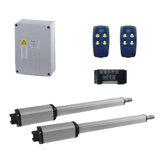
B - Fotocellula di sicurezza Aprimatic C - Dispositivo di comando manuale a chiave (magnetica, digitale, combinatore a tastiera, meccanica, ecc.) D - Apparecchiatura di comando Aprimatic a microprocessore in contenitore stagno (posizionare, possibilmente, al riparo da agenti atmosferici) E - Radioricevente telecomando (possibilità di inserimento all’interno del lampeggiatore) Aprimatic... -
Página 6: Installazione
Installazione 3.1 POSIZIONAMENTO ATTACCHI Nella tabella seguente (C1) sono riportati i dati consigliati per defi nire la posizione degli attacchi dell’attuatore rispetto al centro di rotazione dell’anta. Determinando le quote A e B si stabiliscono: • La corsa utile (C) del pistone •... -
Página 7: Preparazione Fi Ssaggio Posteriore Attuatore Su Pilastri In Muratura
C - Piastra ad ELLE con innesto tramite prigionieri a fi ssaggio chimico o meccanico Cautela • Le dimensioni delle piastre, escluso quelle standard APRIMATIC, vanno proporzionate alle dimensioni delle colonne. • Se si utilizza la piastra di tipo A e si rendesse necessario posizionarla in asse con l’attuatore, occorre modifi... -
Página 8: Fissaggio Piastre Di Ancoraggio
Installazione FISSAGGIO PIASTRE DI ANCORAGGIO FISSAGGIO MECCANICO Ripulire la nicchia da eventuali scorie di cemento o sabbia. Praticare nella nicchia quattro fori (C8 pos. 1) dopo avere segnato la loro posizione utilizzando la piastra di ancoraggio stessa come maschera di foratura. Piastra tipo B Fissare meccanicamente la piastra con tasselli ad espansione “FISCHER”... -
Página 9: Fissaggio Posteriore Provvisorio Attuatore
Installazione FISSAGGIO POSTERIORE PROVVISORIO ATTUATORE Inserire sopra e sotto l’attacco le due boccole antivibranti (C13 pos. 4). Fissare l’attuatore all’attacco tramite il perno verticale (C14 pos. 5) dopo averlo abbondantemente ingrassato. Attenzione Maneggiare con cura l’attuatore durante le fasi di montaggio. POSIZIONAMENTO ANTERIORE ATTUATORE Nel caso si sia stabilito di usare la lunghezza utile massima dello stelo (quote A+B=corsa utile del pistone) occorre utilizzare la dima... -
Página 10: Fissaggio Meccanico Fi Nale Attuatore
Installazione Ricoprire la zona di saldatura, ad avvenuto raffreddamento, di vernice antiruggine (C21). FISSAGGIO MECCANICO FINALE ATTUATORE Spalmare il perno di ancoraggio anteriore dello snodo sferico (C22 pos. 1) di grasso tipo grafi tato. Spalmare lo snodo sferico (C23 pos. 2) di grasso tipo grafi tato. Inserire la testa snodata nel perno (C24 pos. -
Página 11: Rallentamento In Apertura (C29)
Installazione 3.9.3 Rallentamento in apertura (C29) Per sfruttare (solo per la versione ZT44 SF DS ) il rallentamento in apertura è indispensabile utilizzare tutta la corsa dello stelo. Nella versione ZT44 SF DS a stelo tutto dentro rimangono sporgenti 12 mm. 3.9.4 Assemblaggio fi... -
Página 12: Operazioni Fi Nali
Operazioni fi nali 4.1 CONTROLLI REGOLAZIONI Con l’anta in movimento controllare, tramite un dinamometro, la forza di spinta in punta d’anta (D2 pos. 1). Questa non deve mai superare i 15 Kg (147 N). In caso contrario effettuare la regolazione della pressione di esercizio dell’attuatore. -
Página 13: Note Per L'utente
Note per l’utente MANOVRA DI EMERGENZA - USO DELLO SBLOCCO MANUALE Per accedere alla chiave di sblocco è suffi ciente far scorrere lo sportellino (F01 pos. 1), al termine delle operazioni di bloccaggio o sbloccaggio lo sportellino deve essere richiuso. Informazioni Si consiglia di effettuare periodicamente un controllo per constatare il buon funzionamento dell’attuatore, con frequenza... -
Página 14: Technical Data
8 Kg 8 Kg 8 Kg Oil quantity 0,6 lt. 0,6 lt. 0,6 lt. Oil type Aprimatic Oil HC13 Aprimatic Oil HC13 Aprimatic Oil HC13 Protection degree IP 55 IP 55 IP 55 Warning The noise level of the above models, with reference to the working of the operator independently of the gate leaf and the gate post, falls within the maximum limits set by EEC standards. -
Página 15: Choosing The Type Of Automation
Characteristics / Preliminary operations CHOOSING THE TYPE OF AUTOMATION Before mounting, the type of automation must be decided on, on the basis of the characteristics and dimensions of the element to be operated. The ZT 44 hydraulic operator, with its range of different versions, is compatible with the elements listed below. Caution •... -
Página 16: Checking The Operator Components
Suitably powered electric drill - 230 V Spirit level (3-D) Drill bits Graphitized grease Oil -AprimOil HC 13 (specially formulated for Aprimatic) Hollow cutter Ø 67 for photocell and control panel mounting holes Extension lead for welder Zincospray cylinder Electric cable, cross-section 1.5 mm... -
Página 17: Components Layout (B2)
B - Aprimatic safety photocell C - Manual key-operated control unit (magnetic, digital, keyboard combination lock, mechanical, etc.) D - Aprimatic microprocessor control unit in watertight container (if possible, to be fitted in a position that is sheltered from atmospheric agents) E - Aprimatic remote control radio receiver (can be fi... -
Página 18: Installation
Installation 3.1 POSITIONING OF MOUNTINGS The following table (C1) gives the recommended data for fi xing the position of the operator mountings in relation to the center of rotation of the gate leaf. The distances A and B will give: •... -
Página 19: Preparations For Rear Operator Mountings On Masonry Posts
(not supplied by Aprimatic) Caution • The size of the plates, apart from standard APRIMATIC plates, must be proportional to the size of the columns. • If the A-type plate is used and has to be positioned in line with the operator axis, the hook fi ttings must be modifi... -
Página 20: Fitting The Rear Anchorage Plates
Installation FITTING THE REAR ANCHORAGE PLATES PRESSURE FITTING Clean out any traces of cement or sand in the inset. Drill 4 holes in the inset (C8 pos. 1),after marking the position of the holes, using the anchorage plate itself as a drilling template. -
Página 21: Temporary Rear Fi Tting Of The Operator
Installation TEMPORARY REAR FITTING OF THE OPERATOR Fit the two vibration damper bushings (C13 pos. 4) to above and below the mounting. Fit the operator to the mounting with the vertical pin (C14 pos. 5), after greasing abundantly. Warning Handle the operator with care during assembly. FRONTAL POSITIONING OF THE OPERATOR If it has been decided to use the maximum useful length of the rod (distance A+B = useful piston stroke length) then the supplied... -
Página 22: Final Fi Tting Of The Operator
Installation After cooling, apply a coat of rustproof paint to the welded zone (C21). FINAL FITTING OF THE OPERATOR Spread graphitized-type grease on to the frontal anchorage pin of the ball joint (C22 pos. 1). Spread graphitized-type grease on to the ball joint (C23 pos. 2). Fit the jointed head to the pin (C24 pos. -
Página 23: Slowing Down The Operator Opening C29
Installation 3.9.3 Slowing down the operator opening (C29) To use the opening slowing-down (only for ZT44 SF DS version), it is indispensable to use the entire stroke length of the rod. In the ZT44 SF DS version, with the rod fully withdrawn, 12 mm will protrude. -
Página 24: Finals Operations
Finals operations 4.1 CHECKS AND SETTINGS With the gate leaf moving, measure the thrust force at the end of the gate leaf, using a dynamometer (D2 pos. 1). The thrust force must never exceed 15 kg (147 N). If necessary, adjust the working pressure of the operator. -
Página 25: Notes For The User
Notes for the user MANOVRA DI EMERGENZA - USO DELLO SBLOCCO MANUALE To gain access to the release key, it is enough to slide back the hatch (F01 pos. 1); after locking and releasing operations, remember to close the hatch again. Information Periodically check the proper functioning of the operator. -
Página 26: Donnees Techniques
8 Kg 8 Kg 8 Kg 0,6 lt. Quantité huile 0,6 lt. 0,6 lt. Huile type Aprimatic Oil HC13 Aprimatic Oil HC13 Aprimatic Oil HC13 Degré de protection IP 55 IP 55 IP 55 Attention Le niveau de bruit des modèles susmentionnés rentre dans les limites maximales établies par les normes CEE pour le fonctionnement de l’opérateur non fi... -
Página 27: Controle De L'automatisation
Caractéristiques / Opérations préliminaires VERIFICATION DU TYPE D’OPERATEUR Avant d’effectuer le montage, vérifi ez l’automatisation par rapport aux caractéristiques et aux dimensions de l’élément à actionner. L’opérateur oléodynamique ZT 44 est compatible avec les éléments indiqués ci-dessous. Prudence • Une bonne automatisation assure un fonctionnement correct du groupe et réduit les pannes. •... -
Página 28: Controle Des Composants De L'operateur
Masque de protection Niveau à bulle d’aire (tridimensionnel) Electrodes Ø 2 minimum Graisse graphitée Soudeur à l’étain Huile AprimOil HC13 (formulé expressément pour Aprimatic) Perceuse électrique de puissance conforme à l’alimentation 230V Bombe Zincospray Jeu de forets Peinture anti-rouille Fraise à godet ø 67 pour trous de logement photocellules et tableaux Brosses pour peinture à... -
Página 29: Disposition Des Composants (B2)
B - Photocellule de sécurité Aprimatic C - Dispositif de contrôle manuel à clé (magnétique, numérique, par clavier, mécanique, etc.) D - Dispositif de contrôle Aprimatic à microprocesseur placé dans un coffret étanche (à positionner, si possible, à l’abri des agents atmosphériques) E - Récepteur télécommande (possible installation dans le clignotant) Aprimatic... -
Página 30: Installation
Installation 3.1 POSITIONNEMENT DES FIXATIONS Le tableau suivant (C1) présente les données conseillées afi n de défi nir la position des fi xations de l’opérateur par rapport au centre de rotation du vantail. En déterminant les valeurs A et B on établit: •... -
Página 31: Préparation De La Fi Xation Arrière De L'opérateur Sur Des Piliers En Maçonnerie
fi xation chimique ou mécanique. Prudence • Les dimensions des plaques, à l’exception de celles standard APRIMATIC, doivent être proportionnelles aux dimensions des colonnes. • Si vous utilisez la plaque A, qui doit être alignée à l’opérateur, modifi ez les griffes comme indiqué... -
Página 32: Fixation Des Plaques D'ancrage
Installation FIXATION DES PLAQUES D’ANCRAGE Nettoyez la niche des résidus de ciment ou sable. FIXATION MECANIQUE Pratiquez quatre trous (C8 pos. 1) dans la niche, après avoir marqué leur position en utilisant la plaque d’ancrage comme gabarit de perçage. Fixez mécaniquement la plaque avec des goujons à expansion “FISCHER”... -
Página 33: Fixation Arriere Provisoire De L'operateur
Installation FIXATION ARRIERE PROVISOIRE DE L’OPERATEUR Introduisez les deux bagues anti-vibration (C12 pos. 4) au-dessus et au-dessous de la fi xation. Fixez l’opérateur à la plaque à l’aide du pivot vertical (C14 pos. 5) après l’avoir bien graissé. Attention Maniez l’opérateur avec soin pendant les phases de montage. POSITIONNEMENT AVANT DE L’OPERATEUR Au cas où... -
Página 34: Fixation Mecanique Fi Nal De L'operateur
Installation Après le refroidissement, recouvrez la zone de soudure avec de la peinture anti-rouille (C21). FIXATION MECANIQUE FINALE DE L’OPERATEUR Lubrifi ez avec de la graisse graphitée le pivot d’ancrage avant de la rotule (C22 pos. 1). Lubrifi ez avec de la graisse graphitée la rotule (C23 pos. 2). Introduisez la rotule dans le pivot (C24 pos. -
Página 35: Réglage Du Frein En Ouverture (C29)
Installation 3.9.3 Décélération en ouverture (C29) Pour utiliser la fonction de décélération en ouverture (seulement pour la version ZT44 SF DS), il faut utiliser la course entière de la tige. Dans la version ZT44 SF DS, lorsque la tige est complètement rentrée, il y a une saillie de 12 mm. -
Página 36: Opérations Fi Nales
Opérations fi nales 4.1 CONTROLES ET REGLAGES Avec le vantail en mouvement, contrôlez à l’aide d’un dynamomètre la puissance de poussée au bout du vantail (D2 pos. 1). Elle ne doit jamais dépasser 15Kg (147 N). Autrement, réglez la pression de fonctionnement de l’opérateur. -
Página 37: Notes Pour L'utilisateur
Notes pour l’utilisateur MANOEUVRE D’URGENCE - UTILISATION DU DEBLOCAGE MANUEL Pour accéder à la clé de déblocage, il suffi t de faire glisser le guichet (F01 pos. 1); à la fin des opérations de blocage ou déblocage, rappelez-vous de le fermer à nouveau. Informations Il est conseillé... -
Página 38: Merkmale 1.1 Technische Daten
8 Kg 8 Kg 8 Kg Ölmenge 0,6 lt. 0,6 lt. 0,6 lt. Öltyp Aprimatic Oil HC13 Aprimatic Oil HC13 Aprimatic Oil HC13 Schutzart IP 55 IP 55 IP 55 Achtung Bei vorgenannten Modellen liegt der Geräuschpegel (nur des Antriebs losgelöst vom Flügel und Pfeiler) unterhalb der von den EG-Richtlinien vorgesehenen Höchstwerte. -
Página 39: Prüfen Der Antriebsversion
Merkmale / Vorarbeiten PRÜFEN DER ANTRIEBSVERSION Vor Beginn des Einbaus sollte überlegt werden, welche Antriebsversion am besten dem Anwendungszweck entspricht, unter Berücksichtigung der Eigenschaften und Abmessungen des zu bewegenden Objekts. Der hydraulische Antrieb ZT 44 kann mit untenstehenden Ausführungen kombiniert werden. Vorsicht •... -
Página 40: Prüfen Der Antriebsteile
Senkblei Schutzmaske Wasserwaage (3-dimensional) Elektroden Ø 2 mind. Graphitschmiermittel Schweißgerät f. Zinn Öl Typ Aprim Oil HC13 (Spezialöl für APRIMATIC) Elektrobohrer mit angemessener Leistung, 230 V Zinkfl asche Bohrspitzen Rostschutzlack Topffräser Ø 67 zum Ausbohren der Sitze für Lichtschranken und Pinsel für Lockierung... -
Página 41: Anordnung Der Bauteile (B2)
Vorarbeiten ANORDNUNG DER BAUTEILE (B2) A - APRIMATIC-Warnblinker (an eine Stelle anbringen, die von beiden Verkehrsrichtungen gut sichtbar ist) B - APRIMATIC-Sicherheitslichtschranke C - Schlüsselschalter (magnetisch, digital, tastenbetätigt, mechanisch etc.) D - Mikroprozessorbetätigte APRIMATIC-Steuerung in wasserdichtem Gehäuse (möglichst wettergeschützt unterbringen) E - Ferngesteuerter APRIMATIC-Funkempfänger (Einbau innerhalb der Warnblinkers möglich) -
Página 42: Installation
Installation 3.1 POSITIONERUNG DER DREHPUNKTE Nebenstehende Tabelle (C1) zeigt die empfohlenen Daten für das Positionieren der Drehpunkte des Antriebs, die sich nach dem Drehpunkt des Flügels richten. Durch die Maße A und B werden folgende Daten festgelegt: • Arbeitshub (C) des Kolbens •... -
Página 43: Vorbereitung Für Hintere Befestigung Des Antriebs Auf Mauerwerkpfeiler
A - Platte mit Ankerkrampen B - Platte mit Kupplung durch Stiftschrauben. * NACH MASS AUSFÜHREN Chemische oder mechanische Befestigung. (nicht von Aprimatic geliefert) C - L-Platte mit Kupplung durch Stiftschrauben mit chemischer oder mechanischer Befestigung. Vorsicht • Die Abmessungen der Platten (ausgenommen standardmäßige APRIMATIC-Platten) müssen... -
Página 44: Befestigung Der Ankerplatten
Installation BEFESTIGUNG DER ANKERPLATTEN Eventuelle Beton- und Sandspuren gründlich von der Nische entfernen. MECHANISCHE BEFESTIGUNG Nach Markieren der Positionen 4 Löcher (C8 Pos. 1) in die Nische bohren. Dabei ist die Ankerplatte als Bohrungsmaske zuhilfezunehmen. Platte mit Expansionsdübeln “FISCHER” Mind.-Ø 15, Platte Typ B Schraube M8 (C8 Pos. -
Página 45: Vorläufi Ge Hintere Antriebsbefestigung
Installation VORLÄUFIGE HINTERE ANTRIEBSBEFESTIGUNG Die beiden schwingungsdämpfenden Buchsen (C13 Pos. 4) unter und über dem Drehpunkt einsetzen. Den Antrieb mit dem senkrechten Bolzen (C14 Pos. 5) am Drehpunkt festmachen, nachdem dieser reichlich eingeschmiert wurde. Achtung Während der Montage vorsichtig mit dem Antrieb umgehen. VORDERER ANTRIEBSDREHPUNKT Sofern man sich für eine maximale Arbeitslänge der Stange entschieden hat (Maße A+B = Arbeitshub des Kolbens), sollte man... -
Página 46: Endgültige Mechanische Befestigung Des Antriebs
Installation Nach abgeschlossener Abkühlung ist die Schweißfl äche mit einem Rostschutzmittel zu behandeln (C21). ENDGÜLTIGE MECHANISCHE BEFESTIGUNG DES ANTRIEBS Den vorderen Ankerbolzen des Kugelgelenks (C22 pos. 1) mit Graphitschmiermittel abschmieren. Kugelgelenk (C23 pos. 2) mit Graphitschmiermittel abschmieren. Gelenkkopf auf den Bolzen (C24 Pos. 1) stecken und mit Seegerring (C24 Pos. -
Página 47: Bremseinstellung Beim Öffnen (C29)
Installation 3.9.3 Verlangsamung beim Öffnen (C29) Um die Verlangsamung beim Öffnen ausnutzen zu können (nur bei der Version ZT44 SF DS), muss der volle Hub der Stange genutzt werden. Bei der Version ZT44 SF DS steht die Stange bei vollständigem Einzug um 12 mm heraus. 3.9.4 Endgültiger Zusammenbau Schutzkasten (E1 pos. -
Página 48: Abschlußarbeit
Abschlußarbeit 4.1 KONTROLLEN UND EINSTELLUNGEN Bei bewegendem Flügel ist mittels Dynamometer die Schubkraft (D2 pos. 1) am Flügelende zu kontrollieren. Die Schubkraft darf niemals höher als 15 kg (147 N) sein. Andernfalls den Betriebsdruck des Antriebs nachstellen. Einstellventile mittels Schraubenzieher mit breitem, fl... -
Página 49: Hinweise Für Den Benutzer
Hinweise für den Benutzer NOTSTEUERUNGEN - BENUTZUNG DER MANUELLEN ENTRIEGELUNG Zum Erreichen des Entriegelungschlüssels braucht man lediglich die Klappe (F01 Pos. 1) zu verschieben. Nach Beenden der Sperrungs- oder Entriegelungsoperationen muss die Klappe erneut geschlossen werden. Informationen Es wird empfohlen, turnusmäßig eine Prüfung durchzuführen, um das einwandfreie Funktionieren des Triebs festzustellen. -
Página 50: Datos Técnicos
8 Kg 8 Kg 8 Kg 0,6 lt. Cantidad aceite 0,6 lt. 0,6 lt. Tipo de aceite Aprimatic Oil HC13 Aprimatic Oil HC13 Aprimatic Oil HC13 Grado de protección IP 55 IP 55 IP 55 Atención El nivel de ruido de los modelos arriba descritos entra en los límites máximos de las normas CEE limitadamente al funcionamiento del actuador, desvinculado de la hoja y del poste. -
Página 51: Comprobación Elección Automatización
Características / Operaciones preliminares COMPROBACIÓN ELECCIÓN AUTOMATIZACIÓN Antes de efectuar el montaje es necesario comprobar el tipo de automatización elegido en función de las características y de las dimensiones del elemento que se debe accionar. El operador oleodinámico ZT 44 es compatible con los elementos abajo indicados. Precaución •... -
Página 52: Comprobación Components Actuador
Máscara de protección Grasa tipo grafi tado Electrodos ø 2 mínimo Aceite tipo AprimOil HC 13 (aceite expresamente formulado para Soldador de estaño Aprimatic) Taladro eléctrico de potencia adecuada, alimentación 230V. Bombonita spray de cinc Brocas para taladro Pintura antioxidante Fresa hueca ø... -
Página 53: Disposición De Los Componentes (B2)
C - Dispositivo de mando manual a llave (magnético, digital, con teclado, mecánico, etc..) D - Equipo de mando Aprimatic con microprocesador en caja impermeable (colocar, posiblemente, al abrigo de la intemperie) E - Recibidor radio control Aprimatic (posibilidad de incluirlo en el interior del intermitente) F - Caja de derivación impermeable para alimentación actuador (aconsejada) - colocar en modo que los cables no sufran tensiones... -
Página 54: Instalación
Instalación 3.1 COLOCACIÓN DE LAS CONEXIONES En la tabla siguiente (C1) se indican los datos aconsejados para defi nir la posición de las conexiones del actuador respecto al centro de rotación de la hoja. Determinando las cotas A y B se establecen: •... -
Página 55: Preparación Fi Jación Posterior Actuador En Postes De Mampostería
fi jación química o mecánica Precaución • Las dimensiones de las láminas, excluidas las estándar APRIMATIC, deben ser proporcionadas a las dimensiones de las columnas. • Si se utiliza una lámina de tipo A y fuera necesario colocarla en eje con el actuador, es necesario modifi... -
Página 56: Fijación Láminas De Anclaje
Instalación FIJACIÓN LÁMINAS DE ANCLAJE Limpie los huecos de eventuales residuos de cemento o FIJACIÓN MECÁNICA arena. Taladre cuatro agujeros (C8 pos. 1) en el hueco después de haber marcado su posición, utilizando la lámina de anclaje como plantilla para taladrar. Fije mecánicamente la lámina con tacos de expansión Lámina tipo B “FISCHER”... -
Página 57: Fijación Posterior Provisoria Actuador
Instalación FIJACIÓN POSTERIOR PROVISORIA ACTUADOR Introduzca arriba y abajo de la conexión los dos casquillos antivibratorios (C13 pos. 4). Fije el actuador a la conexión por medio del perno vertical (C14 pos. 5) después de haberlo engrasado abundantemente. Atención Manipule con cuidado el actuador durante las fases de montaje. -
Página 58: Fijación Mecánica Fi Nal Actuador
Instalación Después del enfriamiento, aplique sobre la zona de soldadura una mano de pintura antioxidante (C21). FIJACIÓN MECÁNICA FINAL ACTUADOR Aplique grasa grafi tada sobre el perno de anclaje anterior de la articulación esférica (C22 pos. 1). Aplique grasa grafi tada sobre la articulación esférica (C23 pos. 2). Introduzca la cabeza articulada en el perno (C24 pos. -
Página 59: Ensamblaje Fi Nal
Instalación 3.9.3 Deceleración en apertura (C29) Para utilizar la deceleración en apertura (sólo para versión ZT44 SF DS), es indispensable utilizar toda la carrera del vástago. En la versión ZT44 SF DS, con vástago completamente retirado, sobresalen 12 mm. 3.9.4 Ensamblaje fi nal Introduzca el vástago en el cárter de protección (E1 pos. -
Página 60: Operaciones Fi Nal
Operaciones fi nal 4.1 CONTROLES Y REGULACIONES Con la hoja en movimiento compruebe, por medio un dinamómetro, la fuerza de empuje en punta de hoja (D1 pos. 1). Esta no debe nunca superar los 15 kg. (147 N). En caso contrario, efectúe la regulación de la presión de trabajo del actuador. -
Página 61: Notas Para El Usuario
Notas para el usuario MANIOBRA DE EMERGENCIA - USO DEL DESBLOQUEO MANUAL Para acceder a la llave de desbloqueo, es sufi ciente dejar deslizar la tapa (F01 pos. 1); al final de las operaciones de bloqueo o desbloqueo, vuelva a cerrar la tapa. Informaciones Se aconseja efectuar periódicamente un control para comprobar el buen funcionamiento del actuador con frecuencia no superior... - Página 62 SCHEMA DE RACCORDEME T OPERATEUR ZT4/ZT44/ZT40 AVEC ARMOIRE G1 PRO ARMOIRE G1 PRO Récepteur U ICO SE Fermeture Commun gris Ouverture Condensateur Fermeture Commun gris ̶ Ouverture Condensateur ET20- ̶ PC12-E ̶ ER4-...