Sauder Cannery Bridge Serie Instrucciones De Montaje
Ocultar thumbs
Ver también para Cannery Bridge Serie:
- Instrucciones de montaje (64 páginas) ,
- Manual del usuario (36 páginas) ,
- Instrucciones de montaje (52 páginas)
Publicidad
Idiomas disponibles
Idiomas disponibles
Enlaces rápidos
CONTACT US FIRST
CONTACT US FIRST
sauder.com
sauder.com
sauder.com
BEFORE MAKING ANY RETURNS TO THE STORE.
BEFORE MAKING ANY RETURNS TO THE RETAILER.
sauder.com/service
Visit
Prefer the phone? Give us a ring at
Customer Service is available Monday-Friday - 9 a.m. to 5:30 p.m. EST (except holidays)
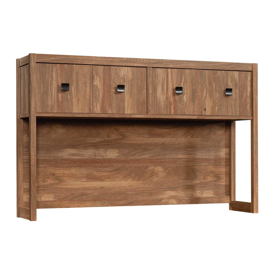
Hutch
Cannery Bridge Collection | Model 429512
Sauder.com
Share your journey!
to order replacement parts, view video assembly tips, or chat with a live rep.
1-800-445-1527
.
Knick-knack
paddywhack,
give your stuff a home.
NOTE: THIS INSTRUCTION
BOOKLET CONTAINS IMPORTANT
SAFETY INFORMATION.
PLEASE READ AND KEEP FOR
FUTURE REFERENCE.
English pg 1-28
Français pg 29-32
Español pg 33-36
Lot # 570162
Purchased: __________________
07/14/21
Publicidad

Manuales relacionados para Sauder Cannery Bridge Serie


Resumen de contenidos para Sauder Cannery Bridge Serie
- Página 1 CONTACT US FIRST CONTACT US FIRST sauder.com sauder.com sauder.com BEFORE MAKING ANY RETURNS TO THE STORE. BEFORE MAKING ANY RETURNS TO THE RETAILER. sauder.com/service Visit to order replacement parts, view video assembly tips, or chat with a live rep. 1-800-445-1527 Prefer the phone? Give us a ring at Customer Service is available Monday-Friday - 9 a.m.
- Página 2 Tip Shown Actual Size Hardware Usage Guide Hammer Assembly Steps 6-28 Not actual size Français 29-32 Pencil Español 33-36 Safety 37-38 Electric drill with 1/8" or 3/8" bit (ONLY in indicated step) Warranty Masking Tape Scissors Page 2 www.sauder.com/service 429512...
- Página 3 Use this part identification to help identify similar parts. LEFT END (1) UPRIGHT (1) RIGHT DOOR (2) RIGHT END (1) TOP BRACE (1) SMALL BACK (1) TOP (1) BOTTOM BRACE (1) LARGE BACK (1) BOTTOM (1) LEFT DOOR (2) 429512 www.sauder.com/service Page 3...
- Página 4 RESTRAINT KIT - 2 2" FLAT HEAD SCREW - 16 1/2" FLAT HEAD SCREW - 16 1/2" PAN HEAD SCREW - 12 3/4" PAN HEAD SCREW - 8 2-1/2" FLAT HEAD SCREW - 2 7/8" MACHINE SCREW - 4 Page 4 www.sauder.com/service 429512...
- Página 5 The arrow in the HIDDEN CAM must point Arrow toward the hole in the edge of the board. Hidden Cam Hole Insert the CAM SCREW or CAM DOWEL into the HIDDEN CAM. Tighten the HIDDEN CAM. 429512 www.sauder.com/service Page 5...
- Página 6 Step 1 Look for this icon. It means a video assembly tip is available at www.sauder.com/service/tips Find the numbered video or scan the QR code. å NOTE: You will need someone's help later in assembly. Remember: å Assemble your unit on a carpeted floor or on the empty Righty tighty.
- Página 7 Fasten the TOP BRACE (F) to the TOP (C). Tighten four HIDDEN CAMS. å NOTE: Be sure the WOOD DOWELS in the BRACE insert into the TOP. 1/2" PAN HEAD SCREW (4 used in this step) These surfaces should be even. 429512 www.sauder.com/service Page 7...
- Página 8 UPRIGHT. 2" FLAT HEAD SCREW (2 used in this step) i t h f a c S u r D E N H I D Notch For support, place packing foam or books here. Page 8 www.sauder.com/service 429512...
- Página 9 NOTE: You should start each SCREW a few turns before completely tightening any of them. å NOTE: Be sure the WOOD DOWELS in the TOP insert into the BACK. 2" FLAT HEAD SCREW (4 used in this step) Arrow Closer together Farther apart Arrow 429512 www.sauder.com/service Page 9...
- Página 10 Fasten the RIGHT END (B) to the TOP (C), TOP BRACE (F), and SMALL BACK (K). Tighten five HIDDEN CAMS. å NOTE: Be sure the WOOD DOWELS in the END insert into the TOP and BACK. Page 10 www.sauder.com/service 429512...
- Página 11 Push two HIDDEN CAMS (2) into the BOTTOM BRACE (G). å NOTE: Be sure the HIDDEN CAMS are completely inserted into the holes. å Turn six CAM SCREWS (3) into the LEFT END (A). Arrow Arrow 429512 www.sauder.com/service Page 11...
- Página 12 Fasten the LEFT END (A) to the TOP (C), TOP BRACE (F), and SMALL BACK (K). Tighten five HIDDEN CAMS. å NOTE: Be sure the WOOD DOWELS in the END insert into the TOP and BACK. NOTE: Do not lift up on or put pressure on the BOTTOM BRACE. Page 12 www.sauder.com/service 429512...
- Página 13 NOTE: You should start each SCREW a few turns before completely tightening any of them. å NOTE: Be sure the WOOD DOWELS in the BOTTOM insert into the ENDS, UPRIGHT, and BACK. 2" FLAT HEAD SCREW (10 used in this step) (9 used) 429512 www.sauder.com/service Page 13...
- Página 14 NOTE: You should start each SCREW a few turns before completely tightening any of them. å Finish fastening the LARGE BACK (L) to your unit using the NAILS (6). NAIL (20 used in this step) 1/2" PAN HEAD SCREW (8 used in this step) Page 14 www.sauder.com/service 429512...
- Página 15 Repeat this step for the other DOORS. NOTE: Be sure the small pin in the KNOB inserts into the small hole in the DOOR. 1/2" FLAT HEAD SCREW (16 used for the HINGES) 7/8" MACHINE SCREW (4 used for the KNOBS) 429512 www.sauder.com/service Page 15...
- Página 16 Peel a BUMPER from the BUMPER CARD (10). Stick the BUMPER onto the DOOR where it comes into contact with the DOOR STOP. å Repeat this step for the other DOORS (H and J). å See the next step for DOOR adjustments. Page 16 www.sauder.com/service 429512...
- Página 17 This page was intentionally left blank. Cette page a été intentionnellement laissée vierge. Esta página fue dejada en blanco intencionalmente. 429512 www.sauder.com/service Page 17...
- Página 18 1) Retire con cuidado las páginas 17-20 del libro y corte a lo largo de todas las líneas discontinuas en esta plantilla. LEFT EDGE OF BASE TOP BORD GAUCHE DU DESSUS DE L’UNITÉ DE BASE BORDE IZQUIERDO DEL PANEL SUPERIOR DE LA UNIDAD BASE Page 18 www.sauder.com/service 429512...
- Página 19 A continuación, taladre un agujero de 3 mm a través de esta ubicación. 2) You will use this template in Step 15. 2) On utilisera ce gabarit à l’Étape 15. 2) Usará esta plantilla en el Paso 15. 429512 www.sauder.com/service Page 19...
- Página 20 This page was intentionally left blank. Cette page a été intentionnellement laissée vierge. Esta página fue dejada en blanco intencionalmente. Page 20 www.sauder.com/service 429512...
- Página 21 To adjust the DOOR in or out (depth), loosen the mounting screw one turn and move the DOOR in or out, as needed. Tighten the mounting screw after making adjustments. Mounting screw (depth) Adjusting screw (horizontal) (vertical adjustment) 429512 www.sauder.com/service Page 21...
- Página 22 Open each FURNITURE TIPPING RESTRAINT KIT (96), and fasten the SAFETY STRAP to the TOP (C). Use the provided SHORT SCREW. Use the SHORT SCREW from the RESTRAINT KIT. SAFETY STRAP Use the SHORT SCREW from the RESTRAINT KIT. SAFETY STRAP Page 22 www.sauder.com/service 429512...
- Página 23 429556. If you're doing this to help a friend, don't å The same attachment method is used for both base units. leave without a bite. This book will show your Hutch being fastened to the 429513. 429512 www.sauder.com/service Page 23...
- Página 24 Tape each template to the corresponding corner of the base unit top. Electric drill with 1/8" bit After drilling each 1/8" hole into the base top, remove the templates. 2-1/2" FLAT HEAD SCREW (2 used in this step) Page 24 www.sauder.com/service 429512...
- Página 25 - Fasten the TIE PLATES (7) to the base unit. Use four 3/4" PAN HEAD SCREWS (14). 3/4" PAN HEAD SCREW (8 used in this step) Electric drill with 1/8" bit Fasten the TIE PLATE to the base unit. 429512 www.sauder.com/service Page 25...
- Página 26 - Fasten the unit to the wall. Use the LONG SCREW through the other end of the SAFETY STRAP and into the 1/8" hole. Mark and drill a 1/8" hole into the wall stud. Electric drill with 1/8" bit Page 26 www.sauder.com/service 429512...
- Página 27 NOTE: You will need to turn the LONG SCREW multiple turns to completely tighten and secure your unit to the wall. Squeeze the wings together and tap the wall anchor into the 3/8" hole in the wall. Mark and drill a 3/8" hole into the wall stud. Electric drill with 3/8" bit 429512 www.sauder.com/service Page 27...
- Página 28 NOTE: Please read the back pages of the instruction booklet for important safety information. å This completes assembly. Clean with a damp cloth. Wipe dry. And to celebrate, why not share your success story at sauder.com or Bottom - 50 lbs. total Page 28 www.sauder.com/service...
- Página 29 REFERENCE DESCRIPTION QUANTITÉ REFERENCE DESCRIPTION QUANTITÉ conserver le livret pour future référence. Pour contacter Sauder en EXTRÉMITÉ GAUCHE ..........1 CHEVILLE EN BOIS ..........27 ce qui concerne cet EXTRÉMITÉ DROITE ..........1 EXCENTRIQUE ESCAMOTABLE ....16 élément, faire référence DESSUS ................1 VIS D'EXCENTRIQUE ..........16 au numéro de lot et...
- Página 30 REMARQUE : S'assurer de bien insérer les EXCENTRIQUES ESCAMOTABLES complètement dans les trous. REMARQUE : S’ a ssurer d’insérer les CHEVILLES EN BOIS dans l’ENTRETOISE dans le DESSUS. Faire tourner six VIS D'EXCENTRIQUE (3) dans l'EXTRÉMITÉ GAUCHE (A). Page 30 www.sauder.com/service 429512...
- Página 31 Fixer un BOUTON (4) à une PORTE DROITE (J). Utiliser une VIS À MÉTAUX 22 mm (16). Fixer deux CHARNIÈRES (5) sur la PORTE DROITE (J). Utiliser deux VIS TÊTE PLATE 13 mm (12). Répéter cette étape pour les autres PORTES. 429512 www.sauder.com/service Page 31...
- Página 32 3 - Fixer les PLAQUES DE LIAISON (7) à l'unité de base. Utiliser sécurité figurant sur les pages arrière du manuel d’instructions. quatre VIS TÊTE GOUTTE DE SUIF 19 mm (14). Ceci complète l'assemblage. Nettoyer avec un tissu humide. Essuyer. Page 32 www.sauder.com/service 429512...
- Página 33 EXTREMO IZQUIERDO ..........1 PASADOR DE MADERA ........27 su referencia futura. Si necesita ponerse en EXTREMO DERECHO ..........1 EXCÉNTRICO ESCONDIDO ......16 contacto con Sauder en PANEL SUPERIOR ............1 BIELA DE EXCÉNTRICO ........16 cuanto a esta unidad, FONDO .................1 POMO ..................4 refiérase al número...
- Página 34 NOTA: Asegúrese de que los PASADORES DE MADERA de la RIOSTRA INFERIOR (G). RIOSTRA se inserten en el PANEL SUPERIOR. NOTA: Asegúrese de que los EXCÉNTRICOS ESCONDIDOS estén completamente insertados en los agujeros. Atornille seis BIELAS DE EXCÉNTRICO (3) en el EXTREMO IZQUIERDO (A). Page 34 www.sauder.com/service 429512...
- Página 35 Fije un POMO (4) a una PUERTA DERECHA (J). Utilice un TORNILLO PARA METAL de 22 mm (16). Fije dos BISAGRAS (5) a la PUERTA DERECHA (J). Utilice dos TORNILLOS DE CABEZA PERDIDA de 13 mm (12). Repita este paso para las otras PUERTAS. 429512 www.sauder.com/service Page 35...
- Página 36 TORNILLOS DE CABEZA REDONDA de 19 mm (14). NOTA: Por favor, lea las páginas de atrás del folleto de instrucciones en cuanto a importante información de seguridad. Esto completa el ensamblaje. Limpiar con un trapo húmedo. Seque con un paño. Page 36 www.sauder.com/service 429512...
- Página 37 Les téléviseurs peuvent être très lourds. De un téléviseur téléviseur. plus, le poids et l’emplacement du tube image ont tendance à rendre les téléviseurs instables et enclins à tomber vers l’ a vant. 429512 www.sauder.com/service Page 37...
- Página 38 El soportar un televisor. diseñadas para soportar un televisor. peso y la ubicación del tubo de imagen tienden a causar la inestabilidad de televisores y por eso tendrán la tendencia a inclinarse hacia adelante. Page 38 www.sauder.com/service 429512...
- Página 39 à compter de la date d'achat la première fois et qui sont signalés à Sauder dans les limites de couverture de la contre tout défaut de matériaux ou de fabrication des composantes de mobilier Sauder.
- Página 40 BEFORE MAKING ANY RETURNS TO THE RETAILER. So, how did it go? Dear Valued Customer: Thanks so much for choosing Sauder® furniture. I hope the Set a world record for speed? purchase and assembly process was a positive experience Feeling good about yourself? and you feel good about the furniture you just built.