Tabla de contenido
Publicidad
Enlaces rápidos
LOVATO ELECTRIC S.P.A.
24020 GORLE (BERGAMO) ITALIA
VIA DON E. MAZZA, 12
TEL. 035 4282111
TELEFAX (Nazionale): 035 4282200
TELEFAX (International): +39 035 4282400
L
E
E-mail info@
ovato
lectric.com
L
E
Web
www.
ovato
lectric.com
ATTENZIONE!!
Questi apparecchi devono essere
installati da personale qualificato,
nel rispetto delle vigenti
normative impiantistiche, allo scopo di
evitare danni a persone o cose.
I prodotti descritti in questo documento
sono suscettibili in qualsiasi momento di
evoluzioni o di modifiche.
Le descrizioni ed i dati a catalogo non
possono pertanto avere alcun valore
contrattuale
INTRODUZIONE
Questo apparecchio semplice ed essenziale,
è caratterizzato da un pannello frontale
chiaro ed intuitivo, che facilita l'utilizzo
anche all'operatore meno esperto. Dispone
inoltre di numerose funzioni di controllo che
di norma sono riscontrabili in apparecchi di
fascia più alta.
DESCRIZIONE
– Controllo del gruppo elettrogeno con
gestione automatica della commutazione
rete-generatore (AMF).
– Ingresso di misura rete trifase
(L1-L2/N-L3).
– Ingresso di misura generatore monofase
(L1-L2/N).
– Alimentazione universale 12-24VDC.
– 1 display a LED alfanumerico, con
4 caratteri.
– 19 LED per visualizzazione stati e misure.
– Tastiera a membrana 8 tasti.
– Interfaccia di comunicazione RS232 per
set-up, controllo remoto e supervisione.
– 6 ingressi digitali programmabili.
– 6 uscite a relè (5NA + 1 contatto in
scambio) programmabili.
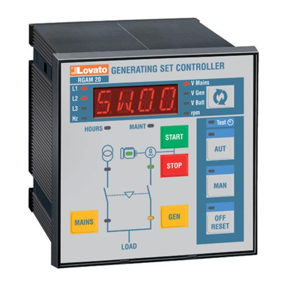
FUNZIONE DEI TASTI FRONTALI
Tasti OFF/RESET, MAN e AUT
Servono per la scelta della modalità di
funzionamento. Il LED acceso indica la
modalità scelta, se è lampeggiante significa
che il controllo remoto è attivo.
Tasti START e STOP
Funzionano solo in modo MAN e servono
per avviare e fermare il gruppo elettrogeno.
Premendo brevemente il tasto START si ha
un tentativo di avviamento, tenendolo
premuto si può prolungare la durata
dell'avviamento. Il LED lampeggiante sul
simbolo motore indica motore in moto con
allarmi inibiti, acceso normalmente al
termine del tempo di inibizione allarmi. Il
motore può essere fermato anche mediante
il tasto OFF/RESET.
Tasti MAINS e GEN
Funzionano solo in modo MAN e servono
per commutare il carico dalla rete al
generatore e viceversa. I LED accesi in
prossimità dei simboli della rete e
generatore indicano le rispettive tensioni
disponibili entro i limiti predefiniti. I LED
accesi in prossimità dei simboli di
commutazione indicano l'avvenuta chiusura
dei dispositivi di commutazione,
lampeggianti se il segnale di ritorno (feed-
back) di effettiva chiusura o apertura dei
dispositivi di commutazione sono errati.
I
GB
F
E
RGAM 20
WARNING!
This equipment is to be installed
by qualified personnel, complying
to current standards, to avoid
damages or safety hazards. Products
illustrated herein are subject to alteration
and changes without prior notice. Technical
data and descriptions in the documentation
are accurate, to the best of our knowledge,
but no liabilities for errors, omissions or
contingencies arising therefrom are
accepted.
INTRODUCTION
This simple, streamlined appliance features
a clear, user-friendly front panel that
facilitates use also by less expert users. It is
also equipped with a wide range of control
functions usually found only on higher range
appliances.
DESCRIPTION
– Gen-set control with automatic
management of the AMF (Automatic
Mains Failure) function
– Three-phase mains measurement input
(L1-L2/N-L3)
– Single-phase gen-set measurement input
(L1-L2/N)
– 12-24VDC universal power supply unit
– 1 alphanumeric LED type display with 4
characters
– 19 LEDs for status and measurement
display
– 8-key membrane keyboard
– RS232 communication interface for
set-up, remote control and supervision
– 6 programmable digital inputs
– 6 programmable relay outputs (5NO +
1 C/O).
KEYBOARD
OFF/RESET, MAN and AUT keys
Press these keys to select the operating
mode. The illuminated LED indicates the
selected operating mode; if it is flashing,
remote control is active.
START and STOP keys
These work in MAN operating mode only,
used to start and stop the engine. By quickly
pressing the START key, one start attempt
takes place; by keeping the START key
pressed, the duration of the start attempts
can be extended. The flashing LED of the
engine symbol denotes engine started, with
alarms inhibited; and is constantly on at the
end of the alarms inhibition time. The engine
can be stopped using the OFF/RESET key.
MAINS and GEN keys
They work in MAN operating mode only,
used to switch the load from mains to
generator and vice versa. The illuminated
LEDs of the mains and generator symbols
indicate the respective voltages are within
preset limits. The illuminated LEDs of the
changeover symbols indicate the actual
closing of switching devices; when flashing,
there is an incorrect feedback signal for the
actual closing or opening of the switching
devices.
UNITÀ DI CONTROLLO PER GRUPPI ELETTROGENI CON COMMUTAZIONE
AUTOMATICA RETE-GENERATORE
GEN-SET CONTROLLER WITH AMF FUNCTION (AUTOMATIC MAINS FAILURE)
UNITE DE CONTROLE POUR GROUPES ELECTROGENES AVEC COMMUTATION
AUTOMATIQUE SECTEUR-GENERATEUR
UNIDAD DE CONTROL PARA GRUPOS ELECTRÓGENOS CON CONMUTACIÓN
AUTOMÁTICA RED-GENERADOR
ATTENTION !
Ces appareils doivent être
installés par un personnel qualifié
en respectant les normes en
vigueur relatives aux installations pour éviter
tout risque pour le personnel et le matériel.
Les produits décrits dans ce document
peuvent à tout moment être susceptibles
d'évolutions ou de modifications. Les
descriptions et les données figurant ne
peuvent en conséquence revêtir aucune
valeur contractuelle.
INTRODUCTION
Cet appareil simple et essentiel est
caractérisé par un panneau avant clair et
intuitif facile à utiliser même par un
opérateur novice. Il dispose de nombreuses
fonctions de contrôle que l'on trouve, en
règle générale, sur les appareils haut de
gamme.
DESCRIPTION
– Contrôle du groupe électrogène avec la
gestion automatique de la commutation
secteur- générateur (AMF) .
– Entrée de mesure secteur triphasée
(L1-L2/N-L3).
– Entrée de mesure générateur
monophasée (L1-L2/N).
– Alimentation universelle12-24VDC.
– 1 afficheur alphanumérique à DEL avec
4 caractères .
– 19 DEL pour afficher les états et les
mesures.
– Clavier à membrane 8 touches.
– Interface de communication RS232 pour
la configuration, le contrôle à distance et
la supervision.
– 6 entrées digitales programmables.
– 6 sorties à relais (5NO + 1 C/O)
programmables.
FONCTIONS DES TOUCHES DU PANNEAU
AVANT
Touches OFF/RESET, MAN et AUT
Elles servent à sélectionner la modalité de
fonctionnement. La Del allumée indique la
modalité sélectionnée, si elle clignote cela
signifie que la commande à distance est
activée.
Touches START et STOP
Elles fonctionnent seulement en modalité
MAN et servent à démarrer et à arrêter le
groupe électrogène. Une brève pression de
la touche START, provoque une tentative de
démarrage, une pression continue, prolonge
la durée du démarrage. La DEL qui clignote
sur le pictogramme du moteur signale que
ce dernier tourne avec les alarmes exclues
car il a été allumé au terme du temps
d'exclusion des alarmes. Pour arrêter le
moteur, appuyez sur la touche OFF/RESET.
Touches MAINS et GEN
Elles fonctionnement seulement en modalité
MAN et servent à commuter la charge du
secteur au générateur et inversement. Les
DEL allumés près des pictogrammes du
secteur et du générateur indiquent les
tensions respectives qui sont disponibles
dans les limites prévues. Les DEL allumées
près des pictogrammes de commutation
signalent la fermeture effective des
dispositifs de commutation; en revanche,
elles clignotent si le signal de retour
ATENCIÓN:
Estos aparatos deben ser
instalados por personal
cualificado y de conformidad con
las normativas vigentes en materia de
equipos de instalación a fin de evitar daños
personales o materiales.
Los productos descritos en este documento
pueden ser modificados o perfeccionados en
cualquier momento. Por tanto, las
descripciones y los datos aquí indicados no
implican algún vínculo contractual.
INTRODUCCIÓN
Este aparato simple y esencial consta de un
panel frontal claro e intuitivo que facilita el
uso hasta a los operadores menos expertos.
También dispone de numerosas funciones
de control que generalmente se encuentran
en aparatos más sofisticados.
DESCRIPCIÓN
– Control para grupos electrógenos con
gestión automática de la conmutación
red-generador (AMF).
– Entrada de medición red trifásica
(L1-L2/N-L3).
– Entrada de medición generador
monofásica (L1-L2/N).
– Alimentación universal 12-24VDC.
– 1 display de LEDs alfanumérico, con
4 caracteres .
– 19 LEDs de visualización estados y
medidas.
– Teclado de membrana con 8 teclas.
– Interfaz de comunicación RS232 para
configuración, control remoto y
supervisión.
– 6 entradas digitales programables.
– 6 salidas de relé (5NA + 1 contacto
intercambio) programables.
FUNCIÓN DE LAS TECLAS FRONTALES
Teclas OFF/RESET, MAN y AUT
Sirven para seleccionar el modo de
funcionamiento. El LED encendido indica el
modo seleccionado y, si es intermitente,
significa que está activado el control remoto.
Teclas START y STOP
Sólo funcionan en modo MAN y sirven para
encender y apagar el grupo electrógeno.
Pulsando un instante la tecla START se
produce una tentativa de encendido,
mientras que manteniéndola pulsada se
puede prolongar la duración del arranque.
El LED intermitente en el símbolo del motor
indica que este último está encendido con
alarmas inhibidas, mientras que se enciende
normalmente al término del tiempo de
inhibición de las alarmas. El motor también
puede pararse mediante la tecla OFF/RESET.
Teclas MAINS y GEN
Sólo funcionan en modo MAN y sirven para
conmutar la carga de la red al generador y
viceversa. Los LEDs encendidos cerca de los
símbolos de la red y del generador indican
las respectivas tensiones disponibles dentro
de los límites predefinidos. Los LEDs
encendidos cerca de los símbolos de
conmutación indican el cierre efectivo de los
dispositivos de conmutación y, si están
intermitentes, señalan que la señal de
retorno (feed-back) relativa al cierre o
apertura efectivos de los dispositivos de
1
Publicidad
Tabla de contenido

Manuales relacionados para LOVATO ELECTRIC RGAM 20

Resumen de contenidos para LOVATO ELECTRIC RGAM 20
- Página 1 UNITÀ DI CONTROLLO PER GRUPPI ELETTROGENI CON COMMUTAZIONE AUTOMATICA RETE-GENERATORE GEN-SET CONTROLLER WITH AMF FUNCTION (AUTOMATIC MAINS FAILURE) UNITE DE CONTROLE POUR GROUPES ELECTROGENES AVEC COMMUTATION LOVATO ELECTRIC S.P.A. AUTOMATIQUE SECTEUR-GENERATEUR 24020 GORLE (BERGAMO) ITALIA VIA DON E. MAZZA, 12 UNIDAD DE CONTROL PARA GRUPOS ELECTRÓGENOS CON CONMUTACIÓN...
- Página 2 (feed-back) de fermeture ou ouverture effective conmutación es errónea. Tasto des dispositifs de commutation est erroné. Tecla Serve per selezionare la misura da Used to select the measurement to be Touche Sirve para seleccionar la medición que se visualizzare. displayed. Elle permet de sélectionner la mesure à...
- Página 3 – Premere START per accedere ai – The display shows “01.01”, the number – Enfoncez START pour accéder aux parámetros. parametri. to the left of the point indicates the paramètres. – En el display se visualizará “01.01”: el – Sul display appare “01.01”, dove il menu, while the number to the right –...
- Página 4 TEST AUTOMATICO AUTOMATIC TEST TEST AUTOMATIQUE TEST AUTOMÁTICO Il test automatico e’ una prova periodica che The automatic test is a check carried out Le test automatique est un essai périodique El test automático consiste en una prueba viene eseguita a scadenze fisse (intervallo periodically at a fixed frequency (the interval qui est exécuté...
- Página 5 “02” GENERALE GENERAL GENERAL GENERAL Default Range P0201 Rapporto TV VT ratio Rapport TP Relación TV 1.0-500.0 P0202 Tipo di collegamento Wiring configuration Types de connexion Tipo de conexión 3PH/1PH P0203 Tensione nominale (V) Rated voltage (V) Tension assignée (V) Tensión nominal (V) 100-50000 P0204...
-
Página 6: Avviamento Motore
“04” AVVIAMENTO MOTORE ENGINE STARTING DEMARRAGE MOTEUR ENCENDIDO MOTOR Default Range P0401 Tensione alternatore Alternator voltage engine started (V) Tension alternateur moteur en Tensión alternador motor encendido 10.0 OFF/3.0-40 motore avviato (V) marche (V) P0402 Tensione generatore Generator voltage engine started (%) Tension générateur moteur en Tensión generador motor OFF/10-100... -
Página 7: Control Motor
P0419 - OFF: relè programmato con la ALT alternate : start-ups are carried out P0419 - OFF: relais programmé avec la CON (consecutivos): La primera mitad del funzione aria compressa disabilitato. alternatively with activation of the start-up fonction air comprimé qui est désactivée. arranque se produce con el relé... - Página 8 “06” CONTROLLO RETE MAINS CONTROL CONTROLE SECTEUR CONTROL RED Default Range P0601 Limite tensione MIN (%) MIN voltage limit (%) Limite tension MINI (%) Límite tensión MIN (%) 70-100 P0602 Ritardo tensione MIN (sec) MIN voltage delay (sec) Retard tension MINI(sec) Retardo tensión MIN (sec) 0-600 P0603...
- Página 9 “07” CONTROLLO GENERATORE GENERATOR CONTROL CONTROLE GENERATEUR CONTROL GENERADOR Default Range P0701 Limite tensione MIN (%) MIN voltage limit (%) Limite tension MINI (%) Límite tensión MIN (%) 70 -100 P0702 Ritardo tensione MIN (sec) MIN voltage delay (sec) Retard tension MINI (sec) Retardo tensión MIN (sec) 0-6000 P0703...
-
Página 10: Puerto Comunicación
“09” TEST E MANUTENZIONE TEST AND MAINTENANCE TEST ET ENTRETIEN TEST Y MANTENIMIENTO Default Range P0901 Abilitazione TEST automatico Automatic test enabling Activation TEST automatique Habilitación Test Automático OFF / ON P0902 Intervallo tra i TEST (giorni) Interval between TESTS (days) Intervalle entre les TEST (jours) Intervalo entre tests (días) 1-60... - Página 11 “11” VARIE MISCELLANEOUS DIVERS VARIOS Default Range P1101 Ore di noleggio (ore) Rent hours (hour) Heures de location (heures) Horas de alquiler (h) OFF/1-60000 P1102 Scelta modo Mode select Choix du mode Selección modo NOR/EJP/ EJP-T/SCR P1103 Ritardo start motore EJP (min) Start engine delay EJP (min) Retard démarrage moteur EJP (min) Retardo arranque motor EJP (min)
- Página 12 POSSIBILI IMPOSTAZIONI DEL POSSIBLE PARAMETER SETTINGS DEFINITIONS POSSIBLES DU PARAMETRE POSIBLES CONFIGURACIONES DEL PARAMETRO PARÁMETRO Impostazione Descrizione Settngs Description Définition Description Configuración Descripción RESET RESET RESET RESET RESET+ MAN RESET+ MAN RESET+ MAN RESET+ MAN AUT+ RESET AUT+ RESET AUT+ RESET AUT+ RESET AUT+ MAN AUT+ MAN...
- Página 13 Codice / Code Lista funzioni d’ingresso Descrizione Functions input list Description Disabilitato Ingresso disabilitato Disabled Input disabled Pressione olio Sensore digitale bassa pressione olio motore Oil pressure Engine oil low pressure digital sensor TEMP Temperatura motore Sensore digitale massima temp. motore Engine temperature Engine max.
- Página 14 Code / Codigo Liste fonctions d’entrée Description Lista funciones de entrada Descripción Désactivé Entrée désactivée Deshabilitado Entrada deshabilitada Pression d’huile Capteur digital basse pression huile moteur Presión aceite Sensor digital baja presión aceite motor TEMP Température moteur Capteur digital temp. maxi moteur Temperatura motor Sensor digital máxima temperatura motor FUEL...
- Página 15 “13” INGRESSI PROGRAMMABILI PROGRAMMABLE OUTPUTS SORTIES PROGRAMMABLES ENTRADAS PROGRAMABLES Default Range P13.1.1 Uscita morsetto 1.1 Output terminal 1.1 Sortie borne 1.1 Salida borne 1.1 Contattore rete Vedi tabella MAINS contactor See list below Contacteur sect. Voir tableau Contactor red Ver tabla P13.1.2 Uscita normale / inversa Normal / reverse output Sortie normale/inverse...
- Página 16 DECE - Se è stata predisposta l’uscita di set, this is activated as soon as the engine is prédisposée, elle est activée dès que le DECE - Si está predispuesta la salida de decelerazione, questa viene attivata non started and is de-activated at the end of moteur est mis en marche et elle est deceleración, ésta se activa ni bien arranca appena il motore si è...
- Página 17 Lo stato del relé risulta invertito se la The status of the relay is inverted if the L’état du relais est inversé si la propriété du El estado del relé resulta invertido si la proprietà del relé è REV. property of the relay is REV. relais est REV.
- Página 18 A10 - Si verifica quando viene rilevato il remains below the threshold for the time marche (alternateur chargeur de batterie, generador), pero la señal de velocidad ‘W’ motore in moto (alternatore carica batteria set. présence tension et/ou fréquence du permanece bajo el umbral durante el tiempo presenza tensione e/o frequenza del A11 - Occurs when engine running is générateur) mais le signal de vitesse ‘W’...
-
Página 19: Propiedad Alarmas
PROPRIETÀ DEGLI ALLARMI ALARMS PROPERTIES PROPRIETES DES ALARMES PROPIEDAD DE LAS ALARMAS La tabella sotto mostra un esempio An example of setting of the properties of Le tableau ci-dessous montre un exemple de La tabla a continuación muestra un ejemplo d’impostazione delle proprietà... - Página 20 IMPOSTAZIONE ALLARMI (valori di default) ALARMS SETTING (default values) Codice allarme Descrizione Alarms code Description Alta temperatura / High temperature Bassa pressione olio / Low oil pressure Guasto sensore di pressione olio / Oil pressure sensor fault Basso livello carburante / Fuel shortage Tensione batteria alta / High battery voltage Tensione batteria bassa / Low battery voltage Batteria inefficiente / Inefficient battery...
- Página 21 DEFINITION DES ALARMES (valeurs par défaut) CONFIGURACIÓN ALARMAS (valores predefinidos) Code alarme Description Código alarmas Descripción Haute Température / Alta temperatura Basse pression d’huile / Baja presión aceite Panne capteur de pression / Avería sensor de presión Bas niveau carburant / Bajo nivel combustible Tension batterie élevée / Tensión batería alta Tension batterie faible / Tensión batería baja Batterie inefficace / Batería ineficaz...
- Página 22 DESCRIZIONE PROPRIETÀ ALLARMI DESCRIPTION OF ALARM PROPERTIES DESCRIPTION DES PROPRIETES DES Descripción propiedad alarmas – Axx.1-1 OFF = allarme disabilitato – Axx.1-1 OFF = alarm disabled ALARMES – Axx.1-1 OFF = Alarma deshabilitada – Axx.1-2 ON = allarme abilitato – Axx.1-2 ON = alarm enabled –...
-
Página 23: Lista Eventi
LISTA EVENTI EVENTS LIST LISTE DES EVENEMENTS LISTA DE EVENTOS 1. E001 Modalità selezionata RESET Operating mode selected RESET Mode sélectionné RESET Modo seleccionado RESET 2. E002 Modalità selezionata MAN Operating mode selected MAN Mode sélectionné MAN Modo seleccionado MAN 3. -
Página 24: Caratteristiche Tecniche
CARATTERISTICHE TECNICHE Uscita contattore rete 1.1 (Uscite in tensione fase L1) Alimentazione ausiliaria Tipo di contatto 1 NC Tensione nominale di batteria 12 o 24V indifferentemente Dati d’impiego UL B300 1A Servizio ausiliario Corrente massima assorbita 250mA a 12V e 130mA a 24V Tensione d’impiego 250V nominale (440V... -
Página 25: Technical Characteristics
TECHNICAL CHARACTERISTICS Mains contactor output 1.1 ( L1 phase voltage output ) Power supply Contact type 1 NC Battery rated voltage 12 or 24V indifferently UL Rating B300 1A Pilot Duty Maximum current consumption 250mA at 12V e 130mA at 24V Rated voltage 250V (440V... -
Página 26: Caracteristiques Techniques
CARACTERISTIQUES TECHNIQUES Sortie contacteur secteur 1.1 ( Sorties sous tension phase L1 ) Alimentation auxiliaire Type de contact Tension assignée de batterie 12 ou 24V indifféremment Catégorie d’emploi selon UL B300 1A Service auxiliaire Courant maximum absorbé 250mA à 12V e 130mA à... -
Página 27: Características Técnicas
CARACTERÍSTICAS TÉCNICAS Salida contactor red 1.1 (Salidas en tensión fase L1) Alimentación auxiliaria Tipo de contacto 1 NC Tensión nominal de batería 12 ó 24V indiferentemente Datos de funcionamiento UL B300 1A Servicio auxiliario Corriente máxima absorbida 250mA a 12V y 130mA a 24V Tensión de funcionamiento 250V... -
Página 28: Wiring Diagrams
SCHEMI DI CONNESSIONE WIRING DIAGRAMS SCHEMAS DE CONNEXION ESQUEMAS DE CONEXIÓN Schema di collegamento per gruppi Wiring diagram for three-phase generating Schéma de connexion pour groupe Esquema de conexión para grupos elettrogeni trifase con alternatore carica set with pre-energised battery charger électrogène triphasé... - Página 29 Connessioni per gruppo elettrogeno Wiring for single-phase generating set Conexions pour groupe électrogène Conexiones para grupo electrógeno monofase monophasé monofásico 1.1 1.2 1.3 LOVATO CAPRA LUIGI 3.6 3.7 1) Teleruttore rete 1) Mains contactor 1) Telerupteur secteur 1) Teeleruptor red 2) Rete 2) Mains 2) Secteur...
-
Página 30: Dimensiones Máximas Y Perforación
Connessioni morsettiere (vista dal retro) Terminal block connections (rear view) Connexions bornies (vue de dos) Conexiones tableros de bornes (vista trasera) MAINS GENERATOR L2-N L2-N 100-415VAC 50 / 60 Hz START DC OUTPUT RELAY DETECT. BATTERY 12/24 VDC RS232 - -- DIGITAL INPUTS DIMENSIONI D’INGOMBRO E FORATURA OVERALL DIMENSIONS AND...