GE Profile PV977 Manual Del Propietario E Instrucciones De Instalación
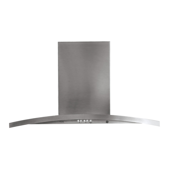
Campanas de ventilación de chimenea para isla
Ocultar thumbs
Ver también para Profile PV977:
- Manual del propietario e instrucciones de instalación (60 páginas) ,
- Manual del propietario y instalación (54 páginas) ,
- Manual del propietário (30 páginas)
Tabla de contenido
Publicidad
Idiomas disponibles
Idiomas disponibles
Enlaces rápidos
ge.com
Safety Instructions
. . . . . . . . . 2, 3
Owner's Manual and
Installation Instructions
Operating Instructions
Light Controls . . . . . . . . . . . . . . . . . . . .4
PV977
Vent Controls . . . . . . . . . . . . . . . . . . . . .4
Grease Filters . . . . . . . . . . . . . . . . . . . .5
Hood Lights . . . . . . . . . . . . . . . . . . . . . .6
Stainless Steel Surfaces . . . . . . . . . . .6
Installation Preparation . . . . . . . .7-15
Vented to the Outside . . . . . . . .16-20
Recirculating . . . . . . . . . . . . . . . . .21-26
. . . . .27, 28
Consumer Support
Consumer Support . . . . . . . . . . . . . 30
Warranty . . . . . . . . . . . . . . . . . . . . . . . 29
Write the model and serial numbers here:
Model # __________________________
Serial # __________________________
You can find them on a label on the inside
of the hood.
49-80550
12-08 JR
Publicidad
Capítulos
Tabla de contenido
Solución de problemas

Manuales relacionados para GE Profile PV977


Resumen de contenidos para GE Profile PV977
-
Página 1: Tabla De Contenido
Safety Instructions ..2, 3 Owner’s Manual and Installation Instructions Operating Instructions Light Controls ....4 PV977 Vent Controls . -
Página 2: Safety Precautions
IMPORTANT SAFETY INFORMATION. READ ALL INSTRUCTIONS BEFORE USING. SAFETY PRECAUTIONS WARNING – WARNING – TO REDUCE TO REDUCE THE RISK THE RISK OF FIRE, ELECTRIC SHOCK OR INJURY OF INJURY TO PERSONS IN THE EVENT OF TO PERSONS, OBSERVE THE FOLLOWING: A RANGE TOP GREASE FIRE, OBSERVE THE FOLLOWING*: A. - Página 3 SAFETY PRECAUTIONS WARNING – WARNING – TO REDUCE THE RISK TO REDUCE THE RISK OF A RANGE TOP GREASE FIRE: OF FIRE, USE ONLY METAL DUCTWORK. ■ A. Never leave surface units unattended at high settings. Do not attempt to repair or replace any...
-
Página 4: Heat Sensor
Using the hood controls. HEAT SENSOR: MEMORY/OFF. To set the memory: This hood is equipped with a heat sensor that will turn A. Press the MEMORY/OFF button. on the fan if excessive temperatures are detected B. Set your desired fan and light settings. (over 70˚C/158˚F) above the cooking surface. -
Página 5: Care And Cleaning
Care and cleaning of the vent hood. ge.com Be sure electrical power is off and all surfaces are cool before cleaning or servicing any part of the vent hood. Metal Grease Filter To remove: Pull downward on the filter lock The metal filter traps grease to release the filter. -
Página 6: Stainless Steel Surfaces
G4 base are available at specialty lighting stores and home building centers. To order replacement bulb no. WB01X10239, contact the GE National Parts Center at 1.800.626.2002 or purchase from your local retailer. 5. Replace lamp lens cover by inserting the three retaining tabs into the three slots and pressing firmly in place. -
Página 7: Installation Instructions
Installation Island Chimney Vent Hood Instructions Questions? Call 800.GE.CARES (800.432.2737) or Visit our Website at: ge.com BEFORE YOU BEGIN PRODUCT DIMENSIONS Read these instructions completely and carefully. 13-1/8" IMPORTANT • — Save these instructions for local inspector’s use. IMPORTANT •... -
Página 8: Installation Preparation
Installation Preparation PREPARE TO INSTALL THE HOOD ADVANCE PLANNING POWER SUPPLY IMPORTANT - (Please read carefully) Ductwork Planning •These vent hoods are equipped for 8" round WARNING: ductwork. •Determine the exact location of the vent hood. FOR PERSONAL SAFETY, THIS APPLIANCE MUST BE PROPERLY GROUNDED. -
Página 9: Duct Fittings
44 ft. *Actual length of straight duct plus duct fitting equivalent. Equivalent length of duct pieces are Total Duct Run based on actual tests conducted by GE Evaluation Engineering and reflect requirements for good venting performance with any ventilation hood. -
Página 10: Tools And Materials Required
Installation Preparation TOOLS AND MATERIALS REQUIRED REMOVE THE PACKAGING (NOT SUPPLIED) CAUTION: Wear gloves to protect against sharp edges. • Remove the duct covers. Safety glasses • Remove the hardware bag, literature package and other boxed parts. Pencil and tape measure •... -
Página 11: Check Installation Hardware
Installation Preparation CHECK INSTALLATION HARDWARE Locate the hardware package packed with the hood and check contents. HARDWARE PACKAGE Locate and count screws Upper vertical supports (4) 4 Wood screws 4 Duct cover clips Lower vertical supports (4) 73 Hood attachment screws (70 required, 3 extra) Duct cover supports (2) Drill 3/16"... -
Página 12: Determine Installation Height
Installation Preparation DETERMINE INSTALLATION HEIGHT PV977 – Island Upper Duct Cover 29.92 • Decorative duct covers are provided to conceal Lower Duct Cover 25.98 Counter to Hood Height the ductwork running to the ceiling. Actual *Possible • This hood can be installed for recirculating Ceiling *Possible VENTED RECIRCULATING... - Página 13 Installation Preparation CONSTRUCT CEILING SUPPORT Plan the Location of the Hood and Ductwork Ceiling • Use a plumb bob to check the location. The countertop/cooktop below the hood Duct covers must be centered with the hood. Hood ducting centerline • The hood should extend beyond the front and rear edge of the cooking appliance.
- Página 14 Installation Preparation CONSTRUCT CEILING SUPPORT (Continued) EXAMPLE B Install cross-framing 2x4 Cross symmetrically over framing wood duct/cooktop centerline 16" Joist supports spacing 10-5/16" 8-1/4" 8" Duct Front Cooktop Align duct outline to center hood of cooktop Top view – ceiling joists run perpendicular to front of hood EXAMPLE C 2x4 Cross 10-5/16"...
- Página 15 Installation Preparation CONSTRUCT CEILING SUPPORT (Continued) 2 x 4 min. Cross framing • Secure each 2 x 4 block with at least four (4), #10 wood screws, 3" long (not supplied). Use 8 wood screws total for the two supports. •...
-
Página 16: Installation-Vented To The Outside
Installation Instructions INSTALLATION—VENTED TO THE OUTSIDE STEP 1 MOUNT TEMPLATE • Align the template with the marks on the ceiling and tape in place. Drill 3/16" Pilot Holes – Be sure the template is oriented correctly Approx. 1-1/2" Deep 4 Places with the front of the hood. - Página 17 Installation Instructions STEP 4 DETERMINE FRAME HEIGHT STEP 5 INSTALL UPPER VERTICAL SUPPORTS TO HOOD ASSEMBLY •Measure exact • Determine how much of the upper vertical Frame ceiling height. Ceiling supports will need to be above the lower supports height •Find the exact to accomplish the frame height determined in height...
- Página 18 Installation Instructions INSTALLATION—VENTED TO THE OUTSIDE STEP 6 CUT DUCT TO LENGTH STEP 7 INSTALL HOOD ASSEMBLY FOR VENTED INSTALLATION TO CEILING SUPPORT WARNING: • Measure from the hood exhaust opening to Two people are required the top of the supports as shown in the figure. to lift and position the hood onto the support.
- Página 19 Installation Instructions STEP 8 CONNECT ELECTRICAL STEP 9 INSTALL DUCT COVER SUPPORTS Verify that power is turned off at the source. • Attach the duct cover supports to the sides of the horizontal and ceiling supports using WARNING: If house wiring is not 2-wire 4 screws per duct cover support.
- Página 20 Installation Instructions INSTALLATION—VENTED TO THE OUTSIDE STEP 10 INSTALL DUCT COVERS STEP 10 INSTALL DUCT COVERS (cont.) IMPORTANT: Two people are required to install • Using screws provided, secure the lower duct the duct covers. covers to the hood assembly from the underside NOTE: If you are installing this hood for recirculating of the hood.
- Página 21 Installation Instructions INSTALLATION—RECIRCULATING STEP 3 INSTALL CEILING SUPPORT STEP 1 MOUNT TEMPLATE AND DEFLECTOR ASSEMBLY • Align the template with the marks on the ceiling and tape in place. •Using the 4 wood screws provided, attach the – Be sure the template is oriented correctly ceiling support using the pilot holes drilled in step 1.
- Página 22 Installation Instructions INSTALLATION—RECIRCULATING STEP 5 DETERMINE FRAME HEIGHT STEP 6 INSTALL UPPER VERTICAL SUPPORT •Measure exact • Using the screws provided, attach the 4 upper Frame ceiling height. vertical supports to the lower vertical supports Ceiling height •Find the exact at the position determined for frame height.
- Página 23 Installation Instructions STEP 7 DETERMINE DUCT LENGTH STEP 8 INSTALL HOOD ASSEMBLY AND INSTALL DUCT TO CEILING SUPPORT WARNING: • Measure from the hood exhaust opening to Two people are required the top of the supports as shown in the figure. to lift and position the hood onto the support.
- Página 24 Installation Instructions INSTALLATION—RECIRCULATING STEP 9 CONNECT ELECTRICAL STEP 10 INSTALL DUCT COVER SUPPORTS Verify that power is turned off at the source. • Attach the duct cover supports to the sides of the horizontal and ceiling supports using WARNING: If house wiring is not 2-wire 4 screws per duct cover support.
- Página 25 Installation Instructions STEP 11 INSTALL DUCT COVERS (cont.) STEP 11 INSTALL DUCT COVERS • Place a duct cover clip onto the bottom of the rear IMPORTANT: Two people are required to install lower duct cover locking the clip into place. the duct covers.
- Página 26 Installation Instructions INSTALLATION—RECIRCULATING STEP 12 INSTALL FILTERS Charcoal Filter Insert the charcoal filter into the opening. Push the latch on both sides toward the center and engage the flange. Metal Grease Filter • Remove the protective film on the grease filter. •...
-
Página 27: Troubleshooting Tips
100 equivalent feet to perform optimally. Using smaller duct pipe or longer equivalent lengths of duct pipe will cause improper venting. GE service technicians cannot correct this issue if installed improperly. Fan fails to circulate air Obstructions in duct work. - Página 28 Before you call for service… Troubleshooting Tips Save time and money! Review the chart below first and you may not need to call for service. Problem Possible Causes What To Do Fan turned on by itself The heat sensor is activated. •This is normal when temperatures below the hood and is in MED setting.
- Página 29 This warranty is extended to the original purchaser and any succeeding owner for products purchased for home use within the USA. If the product is located in an area where service by a GE Authorized Servicer is not available, you may be responsible for a trip charge or you may be required to bring the product to an Authorized GE Service Location for service.
-
Página 30: Consumer Support
Contact Us ge.com If you are not satisfied with the service you receive from GE, contact us on our Website with all the details including your phone number, or write to: General Manager, Customer Relations... - Página 31 Instrucciones Manual del Propietario de Seguridad ....2, 3 e Instrucciones de Instalación Instrucciones de Operación PV977 Controles de la luz ....4 Controles de la ventilación .
-
Página 32: Precauciones De Seguridad
INFORMACIÓN IMPORTANTE DE SEGURIDAD. LEA TODAS LAS INSTRUCCIONES ANTES DE SU USO. PRECAUCIONES DE SEGURIDAD ADVERTENCIA – ADVERTENCIA – PARA REDUCIR PARA REDUCIR EL RIESGO DE INCENDIO, DESCARGA ELÉCTRICA EL RIESGO DE LESIONES A PERSONAS SI SE O LESIONES A PERSONAS, CUMPLA CON LOS PRODUCE UN INCENDIO DE GRASA EN LA ESTUFA, SIGUIENTES PUNTOS: CUMPLA CON LOS SIGUIENTES PUNTOS*:... - Página 33 PRECAUCIONES DE SEGURIDAD ADVERTENCIA – ADVERTENCIA – PARA REDUCIR PARA REDUCIR EL RIESGO DE UN INCENDIO DE GRASA SOBRE EL RIESGO DE INCENDIO, DESCARGA UNA ESTUFA: ELÉCTRICA O LESIONES A PERSONAS, CUMPLA A. Nunca deje unidades de superficie desatendidas CON LOS SIGUIENTES PUNTOS: en configuraciones de calor elevadas.
-
Página 34: Sensor De Calor
Cómo usar los controles de la campana. SENSOR DE CALOR: MEMORY/OFF (memoria/apagado). Esta campana cuenta con un sensor de calor que Para configurar la memoria: enciende el ventilador si se detectan temperaturas A. Presione el botón MEMORY/OFF. excesivas (más de 70 ˚C/158 ˚F) sobre la superficie B. -
Página 35: Cuidado Y Limpieza
Cuidado y limpieza de la campana de ventilación. ge.com Asegúrese de que la energía eléctrica esté apagada y que todas las superficies estén frías antes de limpiar o arreglar cualquier pieza de la campana de ventilación. Filtro de grasa metálico... -
Página 36: Superficies De Acero Inoxidable
Para solicitar una bombilla de repuesto N° WB01X10239, comuníquese con el Centro nacional de piezas GE al 800.626.2002 o adquiérala en su minorista local. 5. Vuelva a colocar la tapa de la bombilla introduciendo las tres lengüetas de... -
Página 37: Instrucciones De Instalación
Instrucciones Campanas de ventilación de instalación de chimenea para isla ¿Preguntas? Llame al 800.GE.CARES (800.432.2737) o visite nuestro sitio Web en: ge.com ANTES DE COMENZAR DIMENSIONES DEL PRODUCTO Lea estas instrucciones por completo y con 13-1/8" detenimiento. IMPORTANTE • — Guarde estas instrucciones para el uso de inspectores locales. -
Página 38: Preparación Para
Preparación para la instalación PREPARACIÓN PARA INSTALAR LA CAMPANA SUMINISTRO DE ENERGÍA PLANIFICACIÓN PREVIA IMPORTANTE – (Tenga a bien leer cuidadosamente) Planificación de conductos ADVERTENCIA: •Estas campanas de ventilación están equipadas con conductos redondos de 8". PARA SEGURIDAD PERSONAL, ESTE APARATO DEBE •Determine la ubicación exacta de la campana CONECTARSE A TIERRA DE MANERA ADECUADA. -
Página 39: Accesorios Para Conductos
ASHRAE. equivalente de las piezas de conductos se encuentra basada en pruebas reales realizadas por el grupo de Ingeniería de Evaluación de GE y reflejan los requisitos para un buen desempeño de ventilación con cualquier campana de ventilación. Recorrido total de los conductos... -
Página 40: Herramientas Y Materiales Requeridos
Preparación para la instalación HERRAMIENTAS Y MATERIALES QUITE EL ENVOLTORIO REQUERIDOS (NO SUMINISTRADOS) PRECAUCIÓN: Se guantes para protegerse de los bordes afilados. • Quite las cubiertas de los conductos. Gafas de seguridad • Quite la bolsa de piezas, el paquete de instrucciones y otras piezas en cajas. -
Página 41: Controle Las Piezas De Instalación
Preparación para la instalación CONTROLE LAS PIEZAS DE INSTALACIÓN Ubique el paquete de hardware embalado con la campana y verifique los contenidos. PAQUETE DE HARDWARE Soportes verticales Ubique y cuente los tornillos superiores (4) Soportes verticales 4 ganchos de la cubierta inferiores (4) del conducto 73 tornillos de sujeción... -
Página 42: Determine La Altura De Instalación
Preparación para la instalación DETERMINE LA ALTURA PV977 – Isla Cubierta de conducto superior 29.92 DE INSTALACIÓN Cubierta de conducto inferior 25.98 Mostrador hasta la altura de la campana • Se ofrecen cubiertas plegables para ocultar los Altura *Altura de instalación *Altura de instalación real del posible CON... -
Página 43: Construya El Soporte Del Cielorraso
Preparación para la instalación CONSTRUYA EL SOPORTE DEL CIELORRASO Planifique la ubicación de la campana Cielorraso y del conducto • Utilice una plomada para verificar la ubicación. Cubiertas El mostrador de encimera/la estufa debajo del conducto Línea central de la campana deben centrarse respecto del conducto de la campana. - Página 44 Preparación para la instalación CONSTRUYA EL SOPORTE DEL CIELORRASO (continuación) EJEMPLO B Instale el armazón cruzado en Soportes de madera del forma simétrica sobre la línea armazón cruzado de 2 x 4 central del conducto/estufa Espacio para viga 10-5/16" de 16" Conducto 8-1/4"...
- Página 45 Preparación para la instalación CONSTRUYA EL SOPORTE DEL CIELORRASO Armazón cruzado (continuación) de 2 x 4 mín. • Fije cada bloque de 2 x 4 con por lo menos cuatro (4) tornillos para madera N°10 de 3” de longitud (no provistos). Utilice un total de 8 tornillos para madera para los dos soportes.
-
Página 46: Instalación-Ventilación Hacia El Exterior
Instrucciones de instalación INSTALACIÓN—VENTILACIÓN HACIA EL EXTERIOR PASO 1 COLOQUE LA PLANTILLA • Alinee la plantilla con las marcas sobre el cielorraso y adhiera en su lugar con cinta. Perfore orificios piloto de 3/16" – Asegúrese de que la plantilla esté bien orientada de aprox. -
Página 47: Paso 4 Determine La Altura Del Armazón
Instrucciones de instalación PASO 4 DETERMINE LA ALTURA PASO 5 INSTALE LOS SOPORTES DEL ARMAZÓN VERTICALES SUPERIORES EN EL MONTAJE DE LA CAMPANA •Mida la altura Altura del exacta del • Determine qué cantidad de los soportes verticales armazón Altura del cielorraso. -
Página 48: Paso 6 Corte El Conducto Con La Longitud Para Una Instalación Ventilada
Instrucciones de instalación INSTALACIÓN—VENTILACIÓN HACIA EL EXTERIOR PASO 6 CORTE EL CONDUCTO CON PASO 7 INSTALE EL MONTAJE DE LA LONGITUD PARA UNA LA CAMPANA EN EL SOPORTE INSTALACIÓN VENTILADA DEL CIELORRASO ADVERTENCIA: • Mida desde la abertura de escape de la campana Se necesitan hasta la parte superior de los soportes como dos personas para levantar y colocar la campana... -
Página 49: Paso 8 Conecte Los Elementos Eléctricos
Instrucciones de instalación PASO 8 CONECTE LOS ELEMENTOS PASO 9 INSTALE LOS SOPORTES ELÉCTRICOS DE LA CUBIERTA DEL CONDUCTO Verifique que la energía esté cortada en la fuente. • Sujete los soportes de la cubierta del conducto a los costados de los soportes horizontales ADVERTENCIA: Si el cableado y de cielorraso usando 4 tornillos por soporte. -
Página 50: Paso 10 Instale Las Cubiertas Del Conducto
Instrucciones de instalación INSTALACIÓN—VENTILACIÓN HACIA EL EXTERIOR PASO 10 INSTALE LAS CUBIERTAS PASO 10 INSTALE LAS CUBIERTAS DEL CONDUCTO DEL CONDUCTO (cont.) IMPORTANTE: Se necesitan dos personas para • Usando los tornillos provistos, fije las cubiertas instalar las cubiertas del conducto. del conducto inferiores al montaje de la campana NOTA: Si va a instalar esta campana para una desde la parte inferior de la campana. -
Página 51: Instalación-Recirculación
Instrucciones de instalación INSTALACIÓN—RECIRCULACIÓN PASO 3 INSTALE EL MONTAJE PASO 1 COLOQUE LA PLANTILLA DEL SOPORTE DEL CIELORRASO • Alinee la plantilla con las marcas sobre el cielorraso Y DEFLECTOR y adhiera en su lugar con cinta. – Asegúrese de que la plantilla esté bien orientada •Utilizando los 4 tornillos para madera provistos, con el frente de la campana. -
Página 52: Paso 6 Instale El Soporte Vertical Superior
Instrucciones de instalación INSTALACIÓN—RECIRCULACIÓN PASO 5 DETERMINE LA ALTURA PASO 6 INSTALE EL SOPORTE VERTICAL DEL ARMAZÓN SUPERIOR •Mida la altura • Utilizando los tornillos provistos, sujete los Altura del exacta del 4 soportes verticales superiores a los soportes cielorraso. armazón Altura del verticales inferiores en la posición determinada... -
Página 53: Paso 7 Determine La Longitud Del Conducto E Instálelo
Instrucciones de instalación PASO 7 DETERMINE LA LONGITUD PASO 8 INSTALE EL MONTAJE DE DEL CONDUCTO E INSTÁLELO LA CAMPANA EN EL SOPORTE DEL CIELORRASO • Mida desde la abertura de escape de la campana hasta la parte superior de los soportes como ADVERTENCIA: Se necesitan dos puede verse en la figura. -
Página 54: Paso 10 Instale Los Soportes De La Cubierta Del Conducto
Instrucciones de instalación INSTALACIÓN—RECIRCULACIÓN PASO 9 CONECTE LOS ELEMENTOS PASO 10 INSTALE LOS SOPORTES ELÉCTRICOS DE LA CUBIERTA DEL CONDUCTO Verifique que la energía esté cortada en la fuente. • Sujete los soportes de la cubierta del conducto ADVERTENCIA: Si el cableado a los costados de los soportes horizontales doméstico no cuenta con un cable de 2 hilos con y de cielorraso usando 4 tornillos por soporte. - Página 55 Instrucciones de instalación PASO 11 INSTALE LAS CUBIERTAS PASO 11 INSTALE LAS CUBIERTAS DEL CONDUCTO (cont.) DEL CONDUCTO • Coloque un gancho de la cubierta del conducto IMPORTANTE: Se necesitan dos personas para en la parte inferior de la cubierta del conducto instalar las cubiertas del conducto.
-
Página 56: Paso 12 Instale Los Filtros
Instrucciones de instalación INSTALACIÓN—RECIRCULACIÓN PASO 12 INSTALE LOS FILTROS Filtro de carbón Introduzca el filtro de carbón dentro de la abertura. Presione la traba sobre ambos lados hacia el centro y sujete la brida. Filtro de grasa metálico • Quite la película protectora del filtro de grasa. •... -
Página 57: Consejos Para La Identificación Y Solución De Problemas
100 pies equivalentes para funcionar correctamente. Utilizar conductos más pequeños o longitudes equivalentes mayores provocará una ventilación inadecuada. Los técnicos de GE no pueden corregir este problema si hay una instalación inadecuada. El ventilador no hace Obstrucciones en el conducto. - Página 58 Antes de llamar al servicio técnico… Consejos para identificación y solución de problemas ¡Ahorre tiempo y dinero! Lea la siguiente tabla primero y quizás no necesite llamar al servicio técnico. Problema Causas posibles Qué hacer El ventilador se encendió Se encuentra activado el sensor •Esto es normal cuando las temperaturas debajo de solo y se encuentra en la de calor.
-
Página 59: Garantía
Estados Unidos. Si el producto está situado en un área que no dispone de servicio por parte de un proveedor de servicio autorizado de GE, podría tener que hacerse cargo de los costes de envío o bien podría solicitársele que lleve el producto a una centro de servicio de GE autorizado para realizar la reparación. -
Página 60: Página Web De Ge Appliances
Solicite una reparación ge.com El servicio de expertos GE está a tan sólo un paso de su puerta. ¡Entre en línea y solicite su reparación cuando le venga cualquier día del año! O llame al 800.GE.CARES (800.432.2737) durante horas normales de oficina.