Tabla de contenido
Publicidad
Idiomas disponibles
Idiomas disponibles
Enlaces rápidos
Publicidad
Tabla de contenido

Manuales relacionados para Wilo Control DigiCon


Resumen de contenidos para Wilo Control DigiCon
- Página 1 Wilo-Control DigiCon/DigiCon-A Einbau- und Betriebsanleitung Installation and operating instructions Notice de montage et de mise en service Istruzioni di montaggio, uso e manutenzione Instrucciones de instalación y funcionamiento...
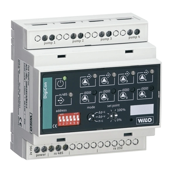
- Página 2 Fig. 1 pump 1 pump 2 pump 3 pump 4 0/0/0 0/0/0 0/0/0 0/0/0 rs 485 address mode set point 100% Baud power rs 485 rs 232...
- Página 3 Fig. 2 0-10V off max min on 24V ebm-ma ebm-sl 0-10V disable 0-10V disable 0-10V off max min on 24V ebm-ma ebm-sl...
- Página 4 Fig. 3 [min 100 % set point 10 V 0-10 V Fig. 4 1 2 3 4 1 2 3 4 pump 1 pump 2 pump 3 pump 4 pump 1 pump 3 DigiCon DigiCon-A DigiCon-A pump 2 pump 4 1 2 3 4 1 2 3 4...
- Página 5 Fig. 5 pump 1 pump 2 pump 3 pump 4 pump 1 pump 2 pump 3 pump 4 pump 1 pump 2 pump 3 pump 4 DigiCon Nr. 1 DigiCon Nr. 2 DigiCon Nr. 64 rs 485 rs 485 rs 485 RS 485 24V DC max.
- Página 6 Fig. 6b pump 1 pump 2 pump 3 pump 4 0/0/0 0/0/0 0/0/0 0/0/0 rs 485 address mode set point 100% Baud power rs 485 rs 232 Fig. 6c...
- Página 7 Einbau- und Betriebsanleitung Installation and operating instructions Notice de montage et de mise en service Istruzioni di montaggio, uso e manutenzione Instrucciones de instalación y funcionamiento...
-
Página 9: Über Dieses Dokument
Gefahr durch elektrische Spannung HINWEIS: ... Signalwörter: GEFAHR! Akut gefährliche Situation. Nichtbeachtung führt zu Tod oder schwersten Verletzungen. WARNUNG! Der Benutzer kann (schwere) Verletzungen erleiden. 'Warnung' beinhaltet, dass (schwere) Personenschäden wahrscheinlich sind, wenn der Hinweis missachtet wird. Einbau- und Betriebsanleitung Wilo-Control DigiCon/DigiCon-A... -
Página 10: Transport Und Zwischenlagerung
Gefahr der Beschädigung durch unsachgemäße Handhabung bei Transport und Lagerung. • Die Schnittstellen-Konverter DigiCon/DigiCon-A sind bei Transport und Zwischenlagerung gegen Feuchtigkeit, Frost und mechanische Beschädi- gung zu schützen. • Sie dürfen keinen Temperaturen außerhalb des Bereiches von - 10°C bis + 70°C ausgesetzt werden. WILO SE 04/2009... - Página 11 Nassläufer-Pumpen • Wilo-TOP-E mit IF-Modul PLR • Wilo-TOP-ED mit 2x IF-Modul PLR • Wilo-Stratos mit IF-Modul Stratos PLR • Wilo-Stratos-D mit 2x IF-Modul Stratos PLR • Wilo-Stratos-Z mit IF-Modul Stratos PLR Trockenläufer-Pumpen • Wilo-VeroLine-IP-E mit IF-Modul PLR • Wilo-VeroTwin-DP-E mit IF-Modul PLR •...
-
Página 12: Technische Daten
+/- 48 VDC Schnittstelle PLR • Max. Kabellänge 200 m • Min. Kabelquerschnitt 2x0,5 mm Schnittstelle RS 485 • Max. Kabellänge 1000 m • Min. Kabelquerschnitt 2x0,5 mm (für max. Leitungslänge) • Kabeltyp (Beispiel) J-Y(St)Y 2x2x0,8 abgeschirmt Tab. 3 WILO SE 04/2009... -
Página 13: Lieferumfang
• Bei Doppelpumpen wird die Schnittstelle PLR des Masters an den Schnittstel- len-Konverter angeschlossen. • Wird bei Doppelpumpen das integrierte Doppelpumpenmanagement nicht benutzt, so sind die beiden Antriebe wie zwei separate Einzelpumpen zu behan- deln. • Steuerfunktionen beziehen sich auf die Doppelpumpe als gesamtes Aggregat. Einbau- und Betriebsanleitung Wilo-Control DigiCon/DigiCon-A... - Página 14 Fig. 2, Pos.4 pumpe ma ist in Betrieb. Meldeleuchte LED ist aus: „Betrieb Doppel- • Doppelpumpe sl steht still. pumpe sl“ (sl = Slave) LED leuchtet dauernd grün: Fig. 2, Pos.5 • Doppelpumpe sl ist in Betrieb. Tab. 5 WILO SE 04/2009...
- Página 15 • Doppelpumpe sl ist in Betrieb. Kontakt wird parallel zur Mel- deleuchte „Betrieb Doppelpumpe sl“ angesteuert. Tab. 6 VORSICHT! Die potenzialfreien Meldekontakte dürfen nur mit einer Betriebsspannungs- art betrieben werden (z.B.: 230 VAC oder 24 VDC). Einbau- und Betriebsanleitung Wilo-Control DigiCon/DigiCon-A...
- Página 16 • Das Signal am Analogeingang „0-10V“ übersteu- ert den am Drehknopf „set point“ eingestellten Wert und den Sollwert, der über den Bus RS 485 gesendet wird. Tab. 7 VORSICHT! An die Steuereingänge darf keine Fremdspannung angelegt werden. WILO SE 04/2009...
- Página 17 • Tab. 8 zeigt die Prioritätsreihenfolge der Steuerkontakte und Busbefehle am DigiCon/DigiCon-A DigiCon/DigiCon-A Steuerkontakt „off“ Höchste Priorität Steuerkontakt „max“ Handbedienebene Steuerkontakt „min“ Steuerkontakt „on“ Busbefehl „max“ Busebene RS 485/PLR Busbefehl „min“ Busbefehl „on“ Niedrigste Priorität Tab. 8 Einbau- und Betriebsanleitung Wilo-Control DigiCon/DigiCon-A...
-
Página 18: Bedienelemente
Einstellungen an die entsprechende Pumpe gesendet. Die Einstellungen werden nur übernommen, wenn über den Bus RS 485 keine Befehle an die entspre- chende Pumpe gesendet wer- den (falls Pumpe ausgeschaltet war, wird sie jetzt eingeschaltet). Tab. 9 WILO SE 04/2009... - Página 19 Baudrate der Schnitt- Fig. 2, Pos.20 stelle RS 485 eingestellt. DIP-Schalter „Z“ An diesen DIP-Schaltern kann Leitungsimpedanz je Leitung ein Abschlusswider- 120 Ω stand der Schnittstelle RS 485 Fig. 2, Pos.21 zugeschaltet werden. Tab. 9 Einbau- und Betriebsanleitung Wilo-Control DigiCon/DigiCon-A...
- Página 20 Wertigkeiten ermittelt, und durch Addition des Wertes des leitungsge- bundenen Anschlusses an die zughörigen Klemmen. Beispiele: Adresse von Pumpe 1 an DigiCon Nr.1(DIP-Schalter 000000): (0)+0=0 Adresse von Pumpe 4 an DigiCon Nr.1(DIP-Schalter 000000): (0)+3=3 Adresse von Pumpe 3 an DigiCon Nr.12(DIP-Schalter 001011): (32+8+4)+2=46 WILO SE 04/2009...
- Página 21 • Der Sollwert über die Schnittstelle RS 485/PLR überschreibt den am Drehknopf „set point“ eingestellten Sollwert. DigiCon/DigiCon-A Handbedienebene Analogeingang „0-10V“ Höchste Priorität Drehknopf „set point“ Busebene RS 485/PLR Sollwert über RS 485/PLR Niedrigste Priorität Tab. 12 Einbau- und Betriebsanleitung Wilo-Control DigiCon/DigiCon-A...
- Página 22 HINWEIS: Die Schnittstellen-Konverter DigiCon und die Handbedienebene Digi- Con-A besitzen eine Kennzeichnungsfläche (20mm x 10mm, Fig. 1, 2, Pos.22), in direkt die Bauteilbezeichnung lt. Anlagenschema eingetragen werden kann. Alternativ kann auf dieser Fläche ein Aufkleber angebracht werden. WILO SE 04/2009...
- Página 23 • Die Steuereingänge für potenzialfreie Steuerkontakte „off“, „max“, „min“ und „on“ (Fig. 4, Pos.1, 2, 3, 4) können durch Anlegen einer Drahtbrücke in ihrer Funktion überprüft werden. • Falls der Analogeingang „0-10V“ belegt ist, wird er durch den Schalter „set“ (Fig. 2, Pos.17) freigegeben. Einbau- und Betriebsanleitung Wilo-Control DigiCon/DigiCon-A...
- Página 24 Kabelschirm überprüfen. Meldeleuchte „Kommunika- • Kabel zwischen Pumpe und tion Pumpe“ leuchtet konstant DigiCon überprüfen. rot. • IF-Modul überprüfen. Kabel zwischen GA und Digi- Kabel reparieren, alternativ Con ist unterbrochen. Pumpe(n) lokal am DigiCon steuern. Tab. 13 WILO SE 04/2009...
- Página 25 Pumpe(n) lokal am DigiCon rot. steuern. • RS 485 Kabel: Anschluss, Abschlusswiderstände und Kabelschirm überprüfen. Tab. 13 Lässt sich die Betriebsstörung nicht beheben, wenden Sie sich bitte an das Fachhandwerk oder an die nächstgelegene Wilo-Kundendienststelle oder Vertretung. Einbau- und Betriebsanleitung Wilo-Control DigiCon/DigiCon-A...
- Página 26 Deutsch 11 Ersatzteile Für Wilo-Control DigiCon und DigiCon-A sind keine Ersatzteile verfügbar. Im Schadensfall ist das komplette Gerät zu tauschen und die defekte Einheit an den Hersteller zurückzugeben. Technische Änderungen vorbehalten! WILO SE 04/2009...
-
Página 27: About This Document
Acutely dangerous situation. Non-observance results in death or the most serious of injuries. WARNING! The user can suffer (serious) injuries. 'Warning' implies that (serious) injury to persons is probable if this information is disregarded. Installation and operating instructions Wilo-Control DigiCon/DigiCon-A... -
Página 28: Transport And Interim Storage
Careless handling during transport and storage can cause damage. • The DigiCon/DigiCon-A interface converters must be protected from moisture, frost and mechanical damage during transport and interim storage • They must not be exposed to temperatures outside the range - 10°C to + 70°C. WILO SE 04/2009... -
Página 29: Intended Use
Glandless pumps • Wilo-TOP-E with IF-Module PLR • Wilo-TOP-ED with 2x IF-Module PLR • Wilo-Stratos with IF-Module Stratos PLR • Wilo-Stratos-D with 2x IF-Module Stratos PLR • Wilo-Stratos-Z with IF-Module Stratos PLR Glanded pump • Wilo-VeroLine-IP-E with IF-Module PLR • Wilo-VeroTwin-DP-E with IF-Module PLR •... -
Página 30: Technical Data
Loop resistance per control input Control input “Analogue In 0...10 V” • Input resistance > 200 kΩ • Overvoltage protection +/- 48 VDC PLR interface • Max. cable length 200 m • Min. cable cross-section 2x0.5 mm Tab. 3 WILO SE 04/2009... -
Página 31: Scope Of Delivery
• DigiCon interface converter or DigiCon-A manual operation level • Installation and operating instructions • CD with documentation and details of the PLR protocol (DigiCon only) • 8-pole (2 x 4) plug (DigiCon-A only) Installation and operating instructions Wilo-Control DigiCon/DigiCon-A... -
Página 32: Description And Function
English 6 Description and function 6. 1 Description of the equipment Wilo-Control DigiCon Wilo-Control DigiCon-A The DigiCon interface converter converts The DigiCon-A manual operation level the PLR interface (point-to-point inter- allows the higher-ranking control of pumps face) into an RS 485 serial digital interface that are connected to DigiCon interface with bus capability. -
Página 33: Signal Lamps
“Double pump opera- LED is off: tion sl” • Double pump sl stationary. signal lamp LED lights up green (sl = Slave) continuously: Fig. 2, item 5 • Double pump sl is operating. Tab. 5 Installation and operating instructions Wilo-Control DigiCon/DigiCon-A... - Página 34 RS 485 interface in the last minute. LED lights up green continuously: - Fault-free communication on the RS 485 interface within the last minute. LED lights up red continuously: - Communication on the interface defective within the last minute. Tab. 5 WILO SE 04/2009...
- Página 35 Contact is activated parallel to the “Double pump operation sl” signal lamp. Tab. 6 CAUTION! The potential-free signal contacts may only be operated with one type of operating voltage (e.g.: 230 VAC or 24 VDC). Installation and operating instructions Wilo-Control DigiCon/DigiCon-A...
- Página 36 • The signal at the analogue input “0-10V” over- rides the value set at the “setpoint” knob and the setpoint transmitted via the RS 485 bus. Tab. 7 CAUTION! No external voltage may be applied to the control inputs. WILO SE 04/2009...
- Página 37 • Δp-v: 0% = H 100% = H • n-c: 0% = min. speed, 100% = max. speed The values H , min. speed and max. speed depend on the pump type. Tab. 9 Installation and operating instructions Wilo-Control DigiCon/DigiCon-A...
- Página 38 Fig. 2, item 20 switch block. DIP switch “Z” At these DIP switches, a termi- Cable impedance 120 nation resistance can be con- Ω nected to the RS 485 interface Fig. 2, item 21 for each cable. Tab. 9 WILO SE 04/2009...
- Página 39 “1” and by adding the value of the hard-wired connection to the corresponding terminals. Examples: Address of pump 1 at DigiCon no.1(DIP switch 000000): (0)+0=0 Address of pump 4 at DigiCon no.1(DIP switch 000000): (0)+3=3 Address of pump 3 at DigiCon no.12(DIP switch001011): (32+8+4)+2=46 Installation and operating instructions Wilo-Control DigiCon/DigiCon-A...
- Página 40 • The setpoint via the RS 485/PLR interface overwrites the setpoint set at the “setpoint” knob. DigiCon/DigiCon-A Manual operation level Analogue input “0-10V” Highest priority “Setpoint” knob Bus level RS 485/PLR Bus level RS 485/PLR Lowest priority Tab. 12 WILO SE 04/2009...
- Página 41 (20mm x 10mm, Fig. 1, 2, item 22), on which the component reference can be indicated according to the plant diagram. Alternatively, a sticker can be applied to this surface. Installation and operating instructions Wilo-Control DigiCon/DigiCon-A...
- Página 42 “max”, “min” and “on” (Fig. 4, items 1, 2, 3, 4) can be checked by connecting a wire bridge. • If the analogue input “0-10V” is occupied, it is released by the “set” switch (Fig. 2, item 17). WILO SE 04/2009...
- Página 43 • Check cable between pump lamp lights up red constantly. and DigiCon. • Check IF-Module. Cable between BMS and Digi- Repair cable, alternatively, con- Con is interrupted. trol pump(s) locally at the Digi- Con. Tab. 13 Installation and operating instructions Wilo-Control DigiCon/DigiCon-A...
- Página 44 • RS 485 cable: check connec- tion, termination resistances and cable screen. Tab. 13 If the fault cannot be remedied, please contact the respective trade or get in touch with your nearest Wilo customer service or agent. WILO SE 04/2009...
-
Página 45: Spare Parts
English 11 Spare parts No spare parts available for Wilo-Control DigiCon and DigiCon-A. In the event of damage, the complete device must be replaced and the defective unit returned to the manufacturer. Subject to change without prior notice. Installation and operating instructions Wilo-Control DigiCon/DigiCon-A... -
Página 46: Signalisation Des Consignes De La Notice
Situation extrêmement dangereuse. Le non-respect entraîne la mort ou des blessures graves. AVERTISSEMENT ! L'utilisateur peut souffrir de blessures (graves). « Avertissement » implique que des dommages corporels (graves) sont vraisemblables lorsque la consi- gne n'est pas respectée. WILO SE 04/2009... -
Página 47: Qualification Du Personnel
DigiCon/DigiCon-A doivent être protégé de l'humidité, du gel et de tout dommage mécanique. • Ils ne doivent pas être exposés à des températures situées en dehors de la plage comprise entre - 10 °C et + 70 °C. Notice de montage et de mise en service Wilo-Control DigiCon/DigiCon-A... -
Página 48: Informations Produit
• Wilo-TOP-E avec module IF PLR • Wilo-TOP-ED avec 2 modules IF PLR • Wilo-Stratos avec module IF Stratos PLR • Wilo-Stratos-D avec 2 modules IF Stratos PLR • Wilo-Stratos-Z avec module IF Stratos PLR Pompes à moteur ventilé • Wilo-VeroLine-IP-E avec module IF PLR •... -
Página 49: Caractéristiques Techniques
• Protection contre les surtensions +/- 48 VDC Interface PLR • Longueur de câble max. 200 m • Section de câble min. 2x0,5 mm (pour une max. longueur de câble) Tab. 3 Notice de montage et de mise en service Wilo-Control DigiCon/DigiCon-A... -
Página 50: Etendue De La Fourniture
• Convertisseur d'interface DigiCon ou commande manuelle DigiCon-A • Notice de montage et de mise en service • CD avec documentation et détails du protocole PLR (DigiCon uniquement) • Fiche à 8 pôles (2 x 4) (DigiCon-A uniquement) WILO SE 04/2009... -
Página 51: Description Et Fonctionnement
• Les fonctions de commande se réfèrent à la pompe double en tant que groupe global. Notice de montage et de mise en service Wilo-Control DigiCon/DigiCon-A... - Página 52 » La DEL est allumée en vert en (ma = Maître) continu : fig. 2, pos. 4 • Pompe simple ou pompe dou- ble ma en service. Tab. 5 WILO SE 04/2009...
- Página 53 RS 485 sans interruption au cours de la dernière minute. La DEL est allumée en rouge en continu : - communication sur l'inter- face défectueuse au cours de la dernière minute. Tab. 5 Notice de montage et de mise en service Wilo-Control DigiCon/DigiCon-A...
-
Página 54: Contacts De Signalisation
« Marche pompe double sl ». Tab. 6 ATTENTION ! Les contacts de signalisation secs ne doivent être utilisés qu'avec une seule nature de tension de service (p. ex. : 230 VAC ou 24 VDC). WILO SE 04/2009... -
Página 55: Entrés De Commande Sur Digicon-A
» ainsi que la valeur de consigne envoyée sur le bus RS 485. Tab. 7 ATTENTION ! Aucune tension perturbatrice ne doit être appliquée aux entrées de com- mande. Notice de montage et de mise en service Wilo-Control DigiCon/DigiCon-A... - Página 56 Contact de commande « min » Contact de commande « on » Instruction de bus « max » Niveau bus RS 485/PLR Instruction de bus « min » Instruction de bus « on » Priorité minimale Tab. 8 WILO SE 04/2009...
-
Página 57: Éléments De Commande
RS 485 à la pompe correspon- dante (si la pompe était désac- tivée, elle est désormais réactivée). Tab. 9 Notice de montage et de mise en service Wilo-Control DigiCon/DigiCon-A... - Página 58 Bauds de l'interface RS 485. fig. 2, pos. 20 Commutateur DIP Ces commutateurs DIP permet « Z » d'activer pour chaque câble Impédance du câble une résistance de terminaison 120 Ω de l'interface RS 485. fig. 2, pos. 21 Tab. 9 WILO SE 04/2009...
-
Página 59: Vitesse En Bauds
4 sur le DigiCon N° 1 (commutateur DIP 000000) : (0)+3=3 adresse de la pompe 3 sur le DigiCon N° 12 (commutateur DIP 001011) : (32+8+4)+2=46 Notice de montage et de mise en service Wilo-Control DigiCon/DigiCon-A... - Página 60 « set point ». DigiCon/DigiCon-A Commande manuelle Entrée analogique « 0-10 V » Priorité maximale Bouton tournant « set point » Valeur de consigne via RS 485/ Priorité minimale Niveau bus RS 485/PLR Tab. 12 WILO SE 04/2009...
- Página 61 REMARQUE: Les convertisseurs d'interface DigiCon et la commande manuelle DigiCon-A possèdent une surface d'identification (20 mm x 10 mm, fig. 1, 2, pos. 22), permettant la saisie directe de la désignation de composant selon le Notice de montage et de mise en service Wilo-Control DigiCon/DigiCon-A...
-
Página 62: Mise En Service
« off », « max », « min » et « on » (fig. 4, pos. 1, 2, 3, 4) en installant un strap. • Si l'entrée analogique « 0-10 V » est occupée, c'est l'interrupteur « set » (fig. 2, pos. 17) qui la débloque. WILO SE 04/2009... - Página 63 Pour tous les travaux d'entretien et de réparation, il convient de commuter les convertisseurs d'interface, la ou les pompes et l'installation hors tension et de les protéger contre toute réactivation intempestive. Notice de montage et de mise en service Wilo-Control DigiCon/DigiCon-A...
-
Página 64: Pannes, Causes Et Remèdes
DigiCon. toujours allumé en rouge. • Vérifier le module IF Le câble entre le GTB et le Réparer la câble ou, autre alter- DigiCon. native, piloter la (les) pompe(s) localement sur le DigiCon. Tab. 13 WILO SE 04/2009... - Página 65 Tab. 13 S'il s'avère impossible de supprimer le défaut de fonctionnement, veuillez- vous adresser à un artisan spécialisé ou à l'agence ou au service après-vente Wilo le plus proche. Notice de montage et de mise en service Wilo-Control DigiCon/DigiCon-A...
-
Página 66: Pièces De Rechange
Français 11 Pièces de rechange Pour le Wilo-Control DigiCon et le DigiCon-A, aucune pièce de rechange n'est nécessaire. En cas de panne, il faut remplacer l'appareil complet et retourner l'unité défec- tueuse au fabricant. Sous réserve de modifications techniques ! -
Página 67: Informazioni Sul Documento
L'inosservanza può provocare infortuni gravi o mortali. AVVISO! Rischio di (gravi) infortuni per l'utente. La parola di segnalazione “Avviso” indica l'elevata probabilità di riportare (gravi) lesioni in caso di mancata osservanza di questo avviso. Istruzioni di montaggio, uso e manutenzione Wilo-Control DigiCon/DigiCon-A... -
Página 68: Qualifica Del Personale
• Proteggeri convertitori di porta DigiCon/DigiCon-A durante il trasporto e il magazzinaggio da umidità, gelo e danni meccanici. • Essi non devono essere esposti a temperature al di fuori del campo di - 10 °C a + 70 °C. WILO SE 04/2009... -
Página 69: Campo D'applicazione
• Wilo-Stratos-Z con modulo IF Stratos PLR Pompe a motore ventilato • Wilo-VeroLine-IP-E con modulo IF PLR • Wilo-VeroTwin-DP-E con modulo IF PLR • Wilo-CronoLine-IL-E con modulo IF PLR • Wilo-CronoTwin-DL-E con 2x moduli IF PLR Tab. 2 Istruzioni di montaggio, uso e manutenzione Wilo-Control DigiCon/DigiCon-A... -
Página 70: Dati E Caratteristiche Tecniche
Italiano 5 Dati e caratteristiche tecniche 5.1 Chiave di lettura Esempio: Wilo-Control DigiCon Control Denominazione della serie DigiCon Denominazione del tipo: DigiCon DigiCon-A Dati tecnici DigiCon DigiCon-A Alimentazione 24 VDC ± 25 % L'alimentazione avviene mediante DigiCon Assorbimento di corrente... - Página 71 • Convertitore di porta DigiCon oppure comando manualeDigiCon-A • Istruzioni di montaggio, uso e manutenzione • CD con documentazione e dettagli del protocollo PLR (solo DigiCon) • a 8 poli (2 x 4) spina (solo DigiCon-A) Istruzioni di montaggio, uso e manutenzione Wilo-Control DigiCon/DigiCon-A...
-
Página 72: Descrizione E Funzionamento
Italiano 6 Descrizione e funzionamento 6.1 Descrizione degli apparecchi Wilo-Control DigiCon Wilo-Control DigiCon-A Il convertitore di porta DigiCon trasforma Il comando manuale DigiCon-A permette il l'interfaccia PLR (interfaccia punto a punto) controllo di gerarchia superiore delle in una interfaccia bus RS 485 seriale, digi- pompe collegate al convertitore di porta tale. -
Página 73: Segnalazioni Luminose
• la pompa doppia sl è ferma. pompa doppia sl” Il LED verde è costantemente (sl = Slave) illuminato: fig. 2, pos. 5 • la pompa doppia sl è in fun- zione. Tab. 5 Istruzioni di montaggio, uso e manutenzione Wilo-Control DigiCon/DigiCon-A... - Página 74 Il contatto viene attivato parallela- mente alla segnalazione luminosa “Funzionamento pompa doppia sl”. Tab. 6 ATTENZIONE! I contatti di segnalazione liberi da potenziale devono essere alimentati solo con un tipo di tensione di esercizio (ad es.: 230 VAC oppure 24 VDC). WILO SE 04/2009...
- Página 75 • Il segnale sull'ingresso analogico “0-10V” supera il valore impostato dalla manopola “set point” e il valore nominale che viene inviato mediante il Bus RS 485. Tab. 7 ATTENZIONE! Non collegare tensioni estranea agli ingressi di comando. Istruzioni di montaggio, uso e manutenzione Wilo-Control DigiCon/DigiCon-A...
- Página 76 Contatto di comando “off” Priorità massima Contatto di comando “max” Comando manuale Contatto di comando “min” Contatto di comando “on” Comando Bus “max” Livello Bus RS 485/PLR Comando Bus “min” Comando Bus “on” Priorità minima Tab. 8 WILO SE 04/2009...
-
Página 77: Elementi Di Comando
“set point” vengono inviate alla relativa pompa. Le impostazioni vengono regi- strate solo se non vengono inviati comandi mediante Bus RS 485 alla relativa pompa (se la pompa è spenta, si accende). Tab. 9 Istruzioni di montaggio, uso e manutenzione Wilo-Control DigiCon/DigiCon-A... - Página 78 RS 485. Interruttore DIP “Z” Su questi interruttori DIP è Impedanza cavo 120 Ω possibile inserire per ogni con- fig. 2, pos. 21 duttore un resistenza termi- nale dell'interfaccia RS 485. Tab. 9 WILO SE 04/2009...
- Página 79 Indirizzo della pompa 1 su DigiCon n. 1 (interruttore DIP 000000): (0)+0=0 indirizzo della pompa 4 su DigiCon n. 1 (interruttore DIP 000000): (0)+3=3 indirizzo della pompa 3 su DigiCon n. 12 (interruttore DIP 001011): (32+8+4)+2=46 Istruzioni di montaggio, uso e manutenzione Wilo-Control DigiCon/DigiCon-A...
- Página 80 • Il valore nominale mediante l'interfaccia RS 485/PLR sovrascrive il valore nomi- nale impostato sulla manopola “set point”. DigiCon/DigiCon-A Comando manuale Ingresso analogico “0-10 V” Priorità massima Manopola “set point” Valore nominale mediante Priorità minima Livello Bus RS 485/PLR RS 485/PLR Tab. 12 WILO SE 04/2009...
- Página 81 (20 mm x 10 mm, fig. 1, 2, pos. 22), in cui è possibile inserire direttamente la denominazione del componente secondo lo schema dell'impianto. In alternativa è possibile incollare un adesivo su questa superficie. Istruzioni di montaggio, uso e manutenzione Wilo-Control DigiCon/DigiCon-A...
-
Página 82: Messa In Servizio
“off”, “max”, “min” e “on” (fig. 4, pos. 1, 2, 3, 4) utilizzando un ponticello a filo. • Se l'ingresso analogico “0-10 V” è occupato, viene abilitato mediante l'interrut- tore “set” (fig. 2, pos. 17). WILO SE 04/2009... - Página 83 Prendere le misure di protezione necessaire per escludere pericoli causati da corrente elettrica. Per tutti i lavori di manutenzione e riparazione è necessario togliere la ten- sione dal convertitore di porta/pompa(e)/impianto e assicurarli contro il reinserimento non autorizzato. Istruzioni di montaggio, uso e manutenzione Wilo-Control DigiCon/DigiCon-A...
-
Página 84: Guasti, Cause E Rimedi
• Controllare il cavo tra pompe “Comunicazione pompe” è e DigiCon. accesa costantemente in • Verificare il modulo IF rosso. Il cavo tra BMS e DigiCon è Riparare il cavo, in alternative interrotto. comandare localmente la/e pompa/e con DigiCon. Tab. 13 WILO SE 04/2009... - Página 85 Tab. 13 Nel caso non sia possibile eliminare l'inconveniente, rivolgersi all'installatore oppure al più vicino punto di assistenza tecnica o rappresentanza Wilo. Istruzioni di montaggio, uso e manutenzione Wilo-Control DigiCon/DigiCon-A...
-
Página 86: Parti Di Ricambio
Italiano 11 Parti di ricambio Per Wilo-Control DigiCon e DigiCon-A non sono disponibili parti di ricambio. In caso di guasto si deve sostituire tutto l'apparecchio e restituire l'unità guasta al costruttore. Salvo modifiche tecniche! WILO SE 04/2009... -
Página 87: Generalidades
¡ADVERTENCIA! El usuario podría sufrir lesiones que podrían incluso ser de cierta gravedad. “Advertencia” implica que es probable que se produzcan daños personales si no se respetan las indicaciones. Instrucciones de instalación y funcionamiento Wilo-Control DigiCon/DigiCon-A... -
Página 88: Cualificación Del Personal
• Los convertidores de interface DigiCon/DigiCon-A deben protegerse frente a la humedad, heladas y daños mecánicos durante el transporte y almacena- miento intermedio. • No deben exponerse a temperaturas fuera del intervalo comprendido entre –10 °C y +70 °C. WILO SE 04/2009... - Página 89 • Wilo-TOP-E con módulo IF PLR • Wilo-TOP-ED con 2 uds. de módulo IF PLR • Wilo-Stratos con módulo IF Stratos PLR • Wilo-Stratos-D con 2 uds. de módulo IF Stratos PLR • Wilo-Stratos-Z con módulo IF Stratos PLR Bombas de rotor seco •...
-
Página 90: Especificaciones Del Producto
Español 5 Especificaciones del producto 5.1 Claves del tipo Ejemplo: Wilo-Control DigiCon Control Denominación de la serie DigiCon Denominación de tipo: DigiCon DigiCon-A Datos técnicos DigiCon DigiCon-A Tensión de alimentación 24 VDC ± 25 % Suministro realizado a través de DigiCon... - Página 91 • Convertidor de interface DigiCon o nivel de mando manual DigiCon-A • Instrucciones de instalación y funcionamiento • CD con documentación y detalles del protocolo PLR (sólo DigiCon) • Enchufe de 8 polos (2 x 4) (sólo DigiCon-A) Instrucciones de instalación y funcionamiento Wilo-Control DigiCon/DigiCon-A...
-
Página 92: Descripción Y Funcionamiento
Español 6 Descripción y funcionamiento 6.1 Descripción de los aparatos Wilo-Control DigiCon Wilo-Control DigiCon-A El convertidor de interface DigiCon con- El nivel de mando manual DigiCon-A per- vierte la interface PLR (interface punto a mite el control a un nivel superior de las punto) en una interface serial digital con bombas que están conectadas a un conver-... -
Página 93: Funciones Y Manejo Del Convertidor De Interface/Nivel De Mando Manual
LED desconectado: “Funcionamiento de • Bomba doble sl parada. bomba doble sl” LED continuamente encendido (sl = slave) con luz verde: Fig. 2, pos. 5 • Bomba doble sl en funciona- miento. Tab. 5 Instrucciones de instalación y funcionamiento Wilo-Control DigiCon/DigiCon-A... -
Página 94: Contactos De Indicación
“Funciona- miento de bomba doble sl” . Tab. 6 ¡PRECAUCIÓN! Los contactos de indicación libres de tensión sólo pueden funcionar con un tipo de tensión de servicio (p. ej.: 230 VAC o 24 VDC). WILO SE 04/2009... -
Página 95: Entradas De Control En Digicon-A
“set point” y el valor de consigna enviado a través del bus RS 485. Tab. 7 ¡PRECAUCIÓN! En las entradas de control no se puede aplicar ninguna tensión externa. Instrucciones de instalación y funcionamiento Wilo-Control DigiCon/DigiCon-A... -
Página 96: Prioridades De Las Órdenes De Bus Y Contactos De Control
• Δp-v: 0 % = H 100 % = H • n-c: 0 % = velocidad mín., 100 % = velocidad máx. Los valores H , veloci- dad mín. y velocidad máx. dependen del tipo bomba. Tab. 9 WILO SE 04/2009... - Página 97 RS 485. Bloque de interrupto- En este bloque de interrupto- res DIP “address” res DIP se ajusta la dirección Fig. 1, pos. 19 del convertidor de interface correspondiente. Tab. 9 Instrucciones de instalación y funcionamiento Wilo-Control DigiCon/DigiCon-A...
- Página 98 Ejemplos: Dirección de bomba 1 a DigiCon nº 1 (interruptor DIP 000000): (0)+0=0 Dirección de bomba 4 a DigiCon nº 1 (interruptor DIP 000000): (0)+3=3 Dirección de bomba 3 a DigiCon nº 12 (interruptor DIP 001011): (32+8+4)+2=46 WILO SE 04/2009...
-
Página 99: Prioridad De Especificación De Valor De Consigna
DigiCon /DigiCon-A Nivel de manejo manual Entrada analógica “0-10 V” Prioridad máxima Botón giratorio “set point” Valor de consigna a través Prioridad mínima Nivel de bus RS 485/PLR de RS 485/PLR Tab. 12 Instrucciones de instalación y funcionamiento Wilo-Control DigiCon/DigiCon-A... -
Página 100: Instalación
INDICACIÓN: Los convertidores de interface DigiCon y el nivel de mando manual DigiCon-A están provistos de una superficie de identificación (20 mm x 10 mm, Fig. 1, 2, pos. 22), en la que se puede registrar directamente la denominación del WILO SE 04/2009... -
Página 101: Puesta En Marcha
“off”, “max”, “min” y “on” (Fig. 4, pos. 1, 2, 3, 4) se puede comprobar estableciendo un puenteado mediante cable. • Si la entrada analógica “0-10 V” está ocupada, ésta es activada por el interrup- tor “set” (Fig. 2, pos. 17). Instrucciones de instalación y funcionamiento Wilo-Control DigiCon/DigiCon-A... -
Página 102: Mantenimiento
DigiCon. temente iluminado en rojo. • Comprobar el módulo IF. El cable entre la GTC y el Digi- Reparar el cable, o bien regular Con está interrumpido. la(s) bomba(s) localmente en el DigiCon. WILO SE 04/2009... - Página 103 Tab. 13 Si no se puede subsanar la avería de funcionamiento, contactar con la empresa especializada o con la delegación o agente del servicio técnico de Wilo más próximo. Instrucciones de instalación y funcionamiento Wilo-Control DigiCon/DigiCon-A...
- Página 104 Español 11 Repuestos Para Wilo-Control DigiCon y DigiCon-A no hay repuestos disponibles. En caso de daños hay que cambiar el aparato completo y remitir al fabricante la unidad defectuosa. Queda reservado el derecho a realizar modificaciones técnicas. WILO SE 04/2009...
- Página 105 Borromeo (Milano) 1065 Baku T +386 1 5838130 Poland T +38 044 2011870 Estonia T +39 25538351 T +994 12 5962372 wilo.adriatic@wilo.si WILO Polska Sp. z.o.o. wilo@wilo.ua WILO Eesti OÜ wilo.italia@wilo.it info@wilo.az 05-090 Raszyn 12618 Tallinn Vietnam T +48 22 7026161...
- Página 106 WILO SE Nortkirchenstraße 100 44263 Dortmund Germany T 0231 4102-0 F 0231 4102-7363 wilo@wilo.com www.wilo.de Wilo-Vertriebsbüros in Deutschland G1 Nord G3 Ost G5 Süd-West G7 West WILO SE WILO SE WILO SE WILO SE Vertriebsbüro Hamburg Vertriebsbüro Dresden Vertriebsbüro Stuttgart Vertriebsbüro Düsseldorf...