ABB Busch-Jalousiecontrol II 6411 U-101-500 Manual De Instrucciones
Ocultar thumbs
Ver también para Busch-Jalousiecontrol II 6411 U-101-500:
- Manual de instrucciones (21 páginas)
Tabla de contenido

Manuales relacionados para ABB Busch-Jalousiecontrol II 6411 U-101-500


Resumen de contenidos para ABB Busch-Jalousiecontrol II 6411 U-101-500
- Página 1 0073-1-6600 Rev. 1 06.01.2006 Busch-Jalousiecontrol® II Unterputzeinsätze 6411 U-101-500 6411 U/S-101-500 GER ENG FRE DUT SPA POL RUS Betriebsanleitung Nur für autorisiertes Elektrofachpersonal...
-
Página 2: Tabla De Contenido
GER ..........3 ENG ........45 FRE .........86 DUT ........132 SPA ........173 POL........215 RUS ........259... -
Página 3: Ger
Einsatzgebiete Einsatzgebiete Die Unterputzeinsätze 6411U-101 bzw. 6411U/S-101 werden eingesetzt zur Steuerung von – Jalousien/Lamellen – Rollladen – Markisen – Lichtkuppelverdeckungen, etc. In dieser Betriebsanleitung wird im folgenden der Begriff „Jalousie“ synonym für die oben aufgezählten Anwendungsmöglichkeiten eingesetzt. Beide Einsätze besitzen verschiedene Betriebsarten - z.B. zum einfachen Fahren der Jalousie oder zur Lamellenverstellung (siehe Kapitel „Betriebsarten“). - Página 4 Einsatzgebiete Besonderheiten der Type 6411U/S-101 Der Unterputzeinsatz 6411U/S-101 besitzt einen zusätzlichen Klemmblock zum Anschluss von Helligkeitssensor und Glasbruchmelder und ein Stellrad zur Einstellung eines Schwellwertes für den Helligkeitssensor. Somit lassen sich wahlweise Helligkeitssensor 6414 und/oder Glasbruchmelder 6413 anschließen.
- Página 5 Einsatzgebiete Fig. 1 Kombinationsmöglichkeiten...
- Página 6 Einsatzgebiete Fig. 2 6411 U/x-101 Einzelsteuerung...
- Página 7 Einsatzgebiete Jalousiecontrol 1 steuert die ganze Gruppe der Jalousiemotoren. Mit allen weiteren Jalousiecontrol- Geräten können die Jalousien auch einzeln gefahren werden. Fig. 3 Jalousiecontrol 1 Jalousiecontrol 2 Jalousiecontrol 3 Eine Kombination der UP-Einsätze 6411U/x-101, 6411 U/x und 6410U-102 ist möglich.
- Página 8 Einsatzgebiete Fig. 4 Nebenstelle 6411 U/x-101 Mehrphasenbetrieb...
- Página 9 Wichtige Hinweise Wichtige Hinweise Ein Mehrphasenbetrieb ist ausschließlich in Deutschland zulässig. Arbeiten am 230 V Netz dürfen nur von Fachpersonal ausgeführt werden! Vor Montage, Demontage Netzspannung freischalten! Durch Nichtbeachtung von Installations- und Bedienungs-hinweisen können Brand und andere Gefahren entstehen! Wird ein Mehrphasenbetrieb (2 Phasen) zur Steuerung und Funktion des Unterputzeinsatzes 6411U/x-101 gewünscht, so sind folgende Bedingungen zwingend nach Vorschrift DIN VDE 0100 zu erfüllen:...
-
Página 10: Wichtige Hinweise
Wichtige Hinweise ACHTUNG LEBENSGEFAHR! Werden unterschiedliche Phasen am Unterputzeinsatz 6411U/x-101 zugelassen, so muss dafür gesorgt werden, dass im Fehlerfall oder bei Arbeiten an der Anlage allpolig abgeschaltet wird. Diese Betriebsart ist ausschließlich in Deutschland zulässig. Bei Einsatz in unterschiedlichen FI Kreisen siehe Schaltbild im Anwenderhandbuch Busch- ®... -
Página 11: Technische Daten
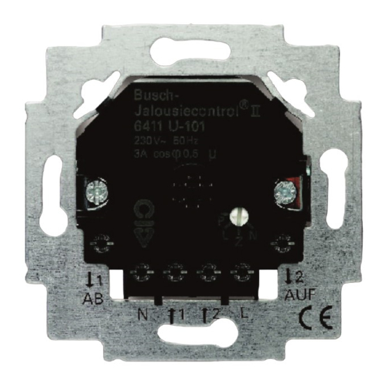
Technische Daten Technische Daten Unterputzeinsatz 6411U/x-101 Nennspannung: 230 V ~ ± 10%, 50 Hz max. Schaltstrom: 3 A cos ϕ 0,5 Leistungsaufnahme: < 1 W Relaiseinschaltdauer ca. 3 Minuten Relaisumschaltpause: > 500 ms Max. Stromaufnahme pro < 3 mA Nebenstelleneingang: Sensoranschluss: SELV-Potential Schutzkleinspannung... - Página 12 Geräteüberblick Geräteüberblick Fig. 5 Geräteüberblick...
- Página 13 Geräteüberblick 1. Unterputzeinsatz 6411U/S-101 2. Netz- /Nebenstellenanschluss 3. Anschluss Jalousiemotor 4. Stellrad zum Wechsel der Betriebsart 5. Abnehmbare Abdeckung für Berührungsschutz (ab Werk montiert) 6. Klemmblock für den Anschluss des Sensors/Melders 7. Stellrad zur Einstellung des Schwellwertes für den Helligkeitssensor 8.
- Página 14 Betriebsarten Betriebsarten a. Wechsel der Betriebsart ● Betriebsartenschalter Fig. 6 6411 U/S-101 6411 U-101 ● Hebeln Sie das Bedienelement mittels Schrauben- dreher über den Rahmen ab. ● Drehen Sie das Stellrad auf die gewünschte Betriebsart. ● Befestigen Sie das Bedienelement wieder in der vorherigen Position.
- Página 15 Betriebsarten b. Betriebsarten Normalbetrieb (N) = Werkseinstellung ● Anwendungsbeispiel: AUF-/AB- Fahren der Jalousie ● Eine kurze Betätigung (Antippen) der Bedienfläche löst einen Fahrbefehl aus, durch den die Jalousie in die obere oder untere Endstellung fährt. Nochmaliges Betätigen unterbricht das Auf- oder Abfahren. ●...
- Página 16 Betriebsarten ● Bei einer langen Betätigung der Bedienfläche fährt die Jalousie für die Dauer der Bedienung getaktet auf- /abwärts. Dauert die Betätigung länger als drei Minuten, so schaltet der Unterputzeinsatz aus. Markisenfunktion (M) ● Diese Betriebsart ist nur in der Version 6411 U/S-101 mit einem angeschlossenem Sonnensensor wirksam.
- Página 17 Betriebsarten Zentrale (Z) ● Anwendungsbeispiel: Ein Jalousiecontrol- Unterputzeinsatz wird als Zentrale für weitere Jalousien eingesetzt. ● Jede Bedienung (kurz oder lang) dieser Zentrale wird als Fahrbefehl (3 Minuten) umgesetzt. Dadurch ist sichergestellt, dass alle untergeordneten Jalousien bis in die Endstellung fahren. ●...
- Página 18 Programmierung Programmierung a. Vorgehensweise ● Aktivieren Sie - analog wie im Kapitel „Betriebsarten“ beschrieben - diese Betriebsart und stecken Sie das jeweilige Bedienelement wieder auf. ● Dabei muss sich die Jalousie in der oberen Endposition befinden. Die Jalousie wird mit einer langen Bedienung auf die gewünschte Position nach unten gefahren.
- Página 19 Programmierung ● Vor dem Einlernen einer Rückfahrzeit muss zuvor eine Abfahrzeit von mindestens 10 Sekunden eingelernt worden sein. ● Hebeln Sie das Bedienelement mittels Schraubendreher wieder inkl. Rahmen ab. ● Verlassen Sie die Betriebsart „Programmierung“ und stellen Sie die ursprünglich gewünschte Betriebsart wieder ein.
- Página 20 Programmierung ● Ist die Programmierung richtig durchgeführt und befindet sich die Jalousie in der oberen Endstellung, fährt die Jalousie bei einem AB-Fahrbefehl die programmierte AB-Fahrzeit nach unten, stoppt für 0,5 s und fährt dann für die Zeit des programmierten Rückfahrimpulses wieder nach oben. ●...
- Página 21 Party-/Aussperrfunktion Party-/Aussperrfunktion ● Die Party-/Aussperrfunktion lässt sich in nur Kombination der UP-Einsätze 6411 U/x-101 und der Bedienelemente 6430-xx oder 6060-xx aktivieren. ● Mit dieser Funktion wird der UP-Einsatz aus einer Gruppensteuerung ausgeschlossen. Das bedeutet, Signale, die über die Nebenstelleneingänge kommen und die Vorort-Bedienung werden ignoriert.
- Página 22 Party-/Aussperrfunktion ● Ein Aktivieren der Partyschaltung deaktiviert die Sonnenschutz-, die Dämmerungs- bzw. die Markisenfunktion. In der Betriebsart Zentral und Programmierung kann die Partyschaltung nicht aktiviert werden.
- Página 23 Montage Montage Netzspannung abschalten! Das Gerät ist für den Einbau in handelsübliche Unterputzdosen geeignet; empfehlenswert ist der Einbau in eine Abzweigschalterdose mit einer Einbautiefe von 60 ● Beachten Sie beim Anschluss die Anschlussbeispiele Fig. 2, 3 und 4. ● Prüfen Sie jeweils die Fahrtrichtung der Jalousie. a.
- Página 24 Montage Ist für den Unterputzeinsatz 6411U/S-101 der Einsatz eines Helligkeitssensors 6414 /Glasbruchmelders 6413 geplant, ist die werkseitige Leitungslänge von ca. 2 m zu berücksichtigen. Anbringen des Bedienelementes Beim IR-Bedienelement 6066 stellen Sie zuvor die gewünschte Adresse ein (siehe Kapitel „Adressierung des IR-Bedienelementes“).
- Página 25 Montage b. Montage in Verbindung mit Nebenstellen Der Unterputzeinsatz kann über Nebenstellen betrieben werden. Dabei ist folgendes zu beachten: – Die maximale Leitungslänge ist abhängig von der maximal zulässigen Brummspannung an den Nebenstelleneingängen. Die Brummspannung darf jedoch 100 V nicht überschreiten (das entspricht in der Praxis mindestens 100 m Leitungslänge).
- Página 26 Bedienung Die Phase für die Nebenstelleneingänge „1“ und „2“ muß gleich und im gleichen Stromkreis sein. Bedienung Die Bedienung der Jalousie ist abhängig vom eingesetzten Bedienelement bzw. vom Einsatz der Sensoren. a. Bedienung über das Bedienelement 6430 Betriebsarten N, M (siehe auch Kapitel „Betriebsarten“) Sie können die Jalousie wie folgt steuern: Kurze Betätigung (Antippen) der oberen Auf = ∆:...
- Página 27 Bedienung Ab = ∇: Kurze Betätigung (Antippen) der unteren Fläche – die Jalousie wird in die untere Endstellung gefahren. Lange Betätigung der unteren Fläche – die Jalousie fährt abwärts, solange die Taste betätigt wird. Nochmalige Betätigung stoppt die Jalousiebewegung. Betriebsart L (siehe auch Kapitel „Betriebsarten“) Kurze Betätigung (Antippen) wirkt analog dem „Normalbetrieb“.
- Página 28 Bedienung b. Bedienung über das IR-Bedienelement 6066 Die manuelle Vorortbedienung sowie die Fernbedienung über den IR-Handsender 6010-25 erfolgen analog zur Betätigung des Bedienelementes 6430. Am IR-Bedienelement 6066 blinkt beim Sendebetrieb die rote LED. Über den IR-Handsender läßt sich das AUF- bzw. AB- Fahren der Jalousie in die beiden MEMO-Speicher M1 bzw.
- Página 29 Bedienung Löschen der MEMO-Speicher ● Drücken Sie die rote ALLES AUS-Taste am Handsender. ● Speichern Sie den ALLES AUS-Zustand in M1 bzw. M2. Vorher muss die Memo-Taste betätigt werden. Eine bestimmte Lamellenstellung läßt sich nicht auf einen MEMO-Speicher legen. Der Zugriff auf die MEMO-Speicher M1 und M2 erfolgt über den IR-Hand- bzw.
- Página 30 Bedienung Der Unterputzeinsatz interpretiert kurze Spannungsimpulse als „kurze Betätigung (Antippen)“ und lange Spannungsimpulse als „lange Betätigung“. Hinweis zu Prioritäten der Bedienung Der Glasbruchmelder hat höchste Priorität. Bei Auslösung werden die Nebenstelleneingänge abgeschaltet. Die Jalousie wird nach unten gefahren und kann nur durch eine Vorortbedienung wieder nach oben gefahren werden.
- Página 31 Helligkeitssensor Helligkeitssensor Der Helligkeitssensor 6414 ist nur in Verbindung mit dem Unterputzeinsatz 6411U/S-101 einsetzbar. a. Funktion Sonnenschutzfunktion Kombinierbar mit Betriebsarten N, L. Vorraussetzung für eine fehlerfreie Funktionalität der Sonnenschutzfunktion ist, das die Jalousie den Sensor überfahren kann. Ist dies nicht gewährleistet muss die Markisenfunktion (siehe Betriebsart M) verwendet werden.
- Página 32 Helligkeitssensor unter dem eingestellten Schwellwert liegenden Wert misst bzw. ein Stellbefehl von einem Bedienelement oder einer Nebenstelle erfolgt. Eine Bedienung durch eine Nebenstelle oder Bedienelement unterbricht die Sonnenschutzfunktion, die manuelle Bedienung wird ausgeführt. Eine erneute Aktivierung der Sonnenschutzfunktion erfolgt durch einen AUF-Fahrbefehl (3 Minuten Fahrzeit) oder durch den nächsten Hell/DunkelÜbergang.
- Página 33 Helligkeitssensor b. Anschluss Der Anschluss kann unter Spannung erfolgen. Gehen Sie bitte wie folgt vor: ● Hebeln Sie ggf. das Bedienelement mittels Schraubendreher inkl. Rahmen ab. ● Hebeln Sie die Abdeckung (siehe Fig. 5, Pos. 5) vom Unterputzeinsatz ab. ● Ziehen Sie den Klemmblock (siehe Fig.
- Página 34 Helligkeitssensor Die beiden Kabel dürfen nicht verpolt werden: S: Helligkeitssensor (hellgrau) Fig. 9 : Masse (weiß) – Verlegen Sie zur Zugentlastung die Sensorleitung im Unterputzeinsatz mit einer kleinen Schlaufe (siehe Fig. 5, Pos. 8). Die Sensorleitung sollte nicht verlängert werden, da ansonsten Funktionsbeeinträchtigungen entstehen.
- Página 35 Helligkeitssensor c. Einstellung (für Bedienelement 6430 bzw. 6066) Zur Einstellung des Schwellwertes für den Helligkeitssensor unabhängig von der aktuellen Helligkeit, gehen Sie bitte wie folgt vor: ● Stellen Sie sicher, dass der Helligkeitssensor an der geplanten Stelle angebracht und unverdeckt ist. ●...
- Página 36 Helligkeitssensor den Maximalwert (Linksanschlag) gedreht werden. Dadurch wird die Programmierung des Helligkeitswertes aktiviert. Die Jalousie fährt (falls diese nicht schon oben ist) als Zeichen der Quittierung dieser Betriebsart nach oben. Jetzt langsam das Stellrad (Fig. 5, Pos. 7) in Richtung abnehmender Helligkeit drehen, bis die Jalousie nach unten fährt.
- Página 37 Glasbruchmelder Glasbruchmelder Der Glasbruchmelder (Art.-Nr. 6413) ist nur in Verbindung mit dem Unterputzeinsatz 6411U/S-101 einsetzbar. Dieser Sensor ist ein optionales Zusatzgerät, welches eine zerspringende Fensterscheibe erkennen kann. Bitte beachten Sie, dass sich der Unterputzeinsatz 6411U/S-101 in Verbindung mit dem Glasbruchmelder nicht als Einbruch-/Überfallschutz eignet, da die hierfür vorgeschriebene Sabotagesicherheit lt.
- Página 38 Glasbruchmelder Während bzw. nach der Auslösung des Schaltbefehls kann die Jalousie weder über den Helligkeitssensor noch über ein Timersignal noch über eine Nebenstelle nach oben gefahren werden. Die herunter gefahrene Jalousie kann nur über das Bedienelement des betroffenen Unterputzeinsatzes wieder nach oben gefahren werden.
- Página 39 Glasbruchmelder b. Anschluss Der Anschluss kann unter Spannung erfolgen. Gehen Sie dazu bitte - wie im Kapitel „Helligkeitssensor“ im Absatz b. beschrieben - vor. Auf die richtige Polung der Zwillings-Schaltlitze ist allerdings nur beim Helligkeitssensor zu achten. Weitere Informationen zur Funktion, Befestigung, etc.
- Página 40 Adressierung IR-Bedienelement Adressierung IR-Bedienelement Die Adresse des IR-Bedienelementes 6066 ist werksseitig auf die Zahl „1” eingestellt. Eine Änderung der Adresse können Sie über das Adressrad auf der Rückseite des IRBedienelementes vornehmen. Beachten Sie bei der Adressierung den „IR-Empfangsbereich“ (Fig. 12 und 13). Fig.
- Página 41 IR-Empfangsbereich IR-Empfangsbereich Fig. 12...
- Página 42 IR-Empfangsbereich Fig. 13...
- Página 43 Störungsbeseitigung Störungsbeseitigung Diagnose Mögl. Ursache/Abhilfe Jalousien fahren – Ausgänge am 6411U/S-101 unterschiedlich (bei wechseln Gruppensteuerung): – Nebenstelleneingänge am 6411U/S-101 vertauschen – Lastleitung von Steuerleitung trennen Jalousie fährt nicht – Nebenstelleneingang mit bei Gruppen- höherer Priorität liegt an (z.B. steuerung: Windalarm) Jalousie fährt nicht: –...
- Página 44 Störungsbeseitigung Bei Einsatz des Timer-Bedienelements 6455 oder 6412- 101 finden Sie weitere Informationen in der zugehörigen Betriebsanleitung. Zusätzlich können folgende IR-spezifische Störungen auftreten: Diagnose Mögl. Ursache/Abhilfe LED an: – Infrarot-Fremdlicht beseitigen – Netzspannung anlegen LED blinkt dauernd: – Dauerfremdsignal beseitigen LED blinkt nicht bei –...
-
Página 45: Eng
Fields of application Fields of application The 6411U-101 and 6411U/S-101 flush-mounted inserts are used to control – shutters/louvres – roller blinds – sunblinds – domelight covers, etc. From now on, the term "shutter" is synonymous for the above listed applications in the operating instructions. -
Página 46: Fields Of Application
Fields of application Special features of the type 6411U/S-101 The flush-type insert 6411U/S-101 has an additional terminal block to connect the brightness sensor and glass breakage detector and a knob for setting a threshold value for the brightness sensor. In this way either the brightness sensor 6414 and/or the glass breakage detector 6413 can be connected. - Página 47 Fields of application Fig. 1 Possible combinations...
- Página 48 Fields of application Fig. 2 6411 U/x-101 Stand-alone control...
- Página 49 Fields of application Shutter control 1 controls the entire shutter motor bank. The shutters can also be moved individually by means of the other shutter control equipment. Fig. 3 Shutter control 1 Shutter control 2 Shutter control 3 UP inserts 6411U/x-101, 6411 U/x and 6410U- 102 can be combined.
- Página 50 Fields of application Fig. 4 Extension 6411 U/x-101 Multi-phase operation...
- Página 51 Important information Important information Multi-phase operation is permissible only in Germany. Work on the 230 V supply system may only be performed by specialist staff! De-energize mains power supply prior to installation and/or disassembly! Failure to observe installation and operating instructions may result in fire and other hazards! If multi-phase (2 phase) operation is desired for the control...
- Página 52 Important information CAUTION DANGER! If different phases are permissible on the 6411U/x-101 flush-mounted insert, it must be ensured that all poles are disconnected in case of faults or when working on the unit. This mode of operation is permissible only in Germany.
-
Página 53: Technical Data
Technical data Technical data Flush-mounted insert 6411U/x-101 Rated voltage: 230 V ~ ± 10%, 50 Hz Max. switching current: 3 A cos ϕ 0,5 Power input: < 1 W Cyclic duration factor of approx. 3 minutes relay (max. movement operation time): Shortest switch-over time: >... - Página 54 Overview of unit Overview of unit Fig. 5 Overview of unit...
-
Página 55: Overview Of Unit
Overview of unit 1. Flush-mounted insert 6411U/S-101 2. Supply system/extension connection 3. Connection for shutter motor 4. Adjustment knob for changing the mode of operation 5. 5. Detachable cover for shock-hazard protection (mounted ex works) 6. Terminal block for connection of the sensor/detector 7. - Página 56 Modes of operation Modes of operation a. Changing the mode of operation ● Operating mode switch Fig. 6 6411 U/S-101 6411 U-101 ● Use a screwdriver to lift the control element over the frame. ● Rotate the adjustment knob to the desired mode of operation.
-
Página 57: Modes Of Operation
Modes of operation b. Modes of operation Normal operation (N) = factory setting ● Application example: Moving the shutter UP/DOWN ● A brief actuation (tapping) of the operating area triggers a motion command that moves the shutter to the upper or lower limit position. If this is done again, the up/down motion is suspended. - Página 58 Modes of operation ● If the operating area is pressed continuously, the shutter moves up/down – timed - as long as this is done. If this is done for more than three minutes, the flush-type insert is switched off. Sun-shutter function (M) ●...
- Página 59 Modes of operation "Central" (Z) ● Application example: A shutter control flush-mounted insert is used as a central control unit for other shutters. ● Any actuation (short or long) of this central control unit is interpreted as a motion command (3 minutes) and put into effect.
- Página 60 Programming Programming a. Procedure ● Activate this mode of operation as described in the chapter "Modes of operation" and re-attach the respective operating element. ● For practical purposes, the shutter is in its upper limit position.The shutter is moved downwards to the desired position by long actuation.
- Página 61 Programming ● Use a screwdriver to lift the control element off with the frame once more. ● Exit the "Programming" mode of operation and reset the originally desired mode of operation. ● Re-attach the operating element. Programming can simplified, if an extension has been installed and is used to program the intermediate position.
- Página 62 Programming b. Clearing the programming ● With the control element removed, switch to “Programming” mode and then back to the previous operating mode. Any existing programming is deleted.
- Página 63 Party/lock-out function Party/lock-out function ● The party/lock-out function can only be activated in combination with the flush-type inserts 6411 U/x-101 and the control elements 6430-xx. ● This function excludes the flush-type insert from a group-controlled unit. That means that signals received via the extension unit inputs and on-site operation are ignored.
- Página 64 Installation Installation Switch off the supply voltage! The unit is suitable for installation in conventional flushmounted boxes; we recommend installation in a branchcircuit switch box with an installation depth of 60 ● When connecting, take note of the connection examples Fig. 2, 3 and 4. ●...
- Página 65 Installation If the use of a brightness sensor 6414/glass breakage detector 6413 is planned for the flush-type insert 6411U/S- 101, the factory-set line length of approx. 2 m must be taken into account. Attaching the operating element First set the desired address on the 6066 IR operating element (see chapter "Setting the address on the IR operating element").
- Página 66 Installation b. Installation in conjunction with extensions The flush-mounted insert can be operated via extensions. Please note the following in this connection: – The maximum line length depends on the maximum permissible ripple voltage at the extension inputs. However, the ripple voltage may not exceed 100 V (in practice this is equivalent to a minimum line length of 100 m).
- Página 67 Operation The phase for extension inputs "1" and "2" must be the same and in the same circuit. Operation Operation of the shutter depends on the operating element used or the employment of sensors. a. Operation via the 6430 operating element Modes of operation N, E (see also chapter on "Modes of operation") Brief actuation (tapping) of the upper surface...
- Página 68 Operation Down = ∇: Brief actuation (tapping) of the lower surface – the shutter is moved into the lower end position. Long actuation of the lower surface – The shutter moves down as long as the key is pressed. Pressing it again stops the shutter motion. Mode of operation L (see also chapter on "Modes of operation") Brief actuation (tapping) has the same effect as in “normal...
- Página 69 Operation b. Operation via the 6066 IR operating element Manual local operation and remote control via the IR handheld transmitter (Article no. 6010-25) are effected in the same way as in the actuation of the 6430 operating element. The red LED on the 6066 IR operating element flashes in the transmit mode.
- Página 70 Operation The upwards and downwards movement of the shutter can be stored in the M1 or M2 MEMO memories via the IR hand-held transmitter: ● Actuate the operating elements or the IR hand-held transmitter in the desired direction (UP/DOWN). ● Save the direction in M1 or M2.
- Página 71 Operation c. Operation via extensions All types of signal generators are suitable that generate a 230 V signal (no permanent signal) for extension units “1” and “2” (see fig. 1). Operation depends on the respective range of function of the extension and on the selected mode of operation. The flush-type insert interprets short voltage pulses as “short actuation (tapping)”...
- Página 72 Brightness sensor Brightness sensor The brightness sensor 6414 can only be used in conjunction with the 6411U/S-101 flush-mounted insert. a. Function Sunshade function Can be combined with operating modes N, L. Precondition for the faultless sun protection functionality is that the shutter can cross the sensor. If this is not ensured, then the sun-blind function (see operating mode M) must be used.
- Página 73 Brightness sensor adjusting command is received from an operating element or an extension. The sunshade function is interrupted by operation from an extension or operating element and manual operation is executed. The sunshade function is re-activated by a move up command (3 minutes motion time) or by the next light/ dark changeover.
- Página 74 Brightness sensor b. Connection Connection can be made under voltage. Proceed as follows: ● If necessary, use a screwdriver to lift off the control element with the frame. ● Lift the cover (see Fig. 5, Pos. 5) off the flushmounted insert.
- Página 75 Brightness sensor The polarity of the two cables must be respected: S: Brightness sensor (light grey) Fig. 9 : Earth (white) – Lay the sensor lead in the flush- mounted insert with a small loop for strain relief (see Fig. 5, Pos. 8). Do not extend the sensor lead, since this could lead to impaired performance.
- Página 76 Brightness sensor c. Setting (for operating element 6430 or 6066) Please proceed as follows to set the threshold value for the brightness sensor irrespective of the current brightness: ● Ensure that the brightness sensor is attached at the planned position and uncovered. ●...
- Página 77 Brightness sensor maximum value (all the way to the left). In this manner, the programming of the brightness value is activated. The shutter moves upwards (if it is not already at the top) as an acknowledgement of this mode of operation. Next, slowly turn the adjustment knob (Fig.
- Página 78 Glass break detector Glass break detector The glass break detector (Article. no. 6413) can only be used in conjunction with the 6411U/S-101 flush-mounted insert. This sensor is an optional accessory unit which can detect a bursting window pane. Please note that the 6411U/S-101 flush- mounted insert in conjunction with the glass break detector is not suitable as a burglary/ robbery protection device, since there is no...
-
Página 79: Glass Break Detector
Glass break detector The shutter cannot be moved upwards via the brightness sensor, a timer signal or via an extension during or after triggering of the switching command. Once the shutter has moved down, it can only be moved up-wards again via the operating element of the flushmounted insert concerned. - Página 80 Glass break detector You will find further information on the function and attachment in the operating manual of the glass break detector.
- Página 81 Addressing the IR control element Addressing the IR control element The address on the 6066 IR operating element is set ex works at number "1". You can change the address via the rotary addressing device on the back of the IR operating element.
- Página 82 IR receiving range IR receiving range Fig. 12...
- Página 83 IR receiving range Fig. 13...
- Página 84 Fault elimination Fault elimination Diagnosis Poss. cause/remedy Shutters move – change outputs on the variably (with group 6411U/S 6411U/S-101 control): – exchange extension inputs on the 6411U/S-101 – Disconnect load line from control line The shutter does – Extension unit with higher not move if group priority is applied (e.g.
-
Página 85: Fault Elimination
Fault elimination You will find further information about the use of a 6455 oder 6412-101 timer operating element in the operating manual. In addition, the following IR-specific faults can occur: Diagnosis Poss. cause/remedy LED on: – eliminate IR light from external source –... -
Página 86: Domaines D'utilisation
Domaines d’utilisation Domaines d’utilisation Les insertions encastrées 6411U-101 et/ou 6411U/S-101 sont utili-sées pour la commande de: – jalousies/lamelles – volets roulants, stores en toile – recouvrements pour coupole en verre, etc. Dans ces instructions de service, le terme "jalousie" estutilisé par la suite comme synonyme pour les possibilités d’application énumérées ci-dessus. - Página 87 Domaines d’utilisation Particularités des types 6411U/S-101 L'insert encastré 6411U/S-101 est équipé d'un bornier supplémentaire permettant de raccorder un capteur de luminosité et un détecteur de bris de vitre ainsi que d'une mollette pour régler une valeur seuil pour le capteur de luminosité.
- Página 88 Domaines d’utilisation Fig. 1 Possibilités de combinaison...
- Página 89 Domaines d’utilisation Fig. 2 6411 U/x-101 Commande individuelle...
- Página 90 Domaines d’utilisation Le contrôle de jalousie 1 commande le groupe entier desmoteurs de jalousie. Avec tous les autres appareils decontrôle de jalousie, les jalousies peuvent être aussi action-nées individuellement. Fig. 3 Contrôle de Contrôle de Contrôle de jalousie 1 jalousie 2 jalousie 3 Il est possible de combiner les insertions 6411U/x-101, 6411 U/x et 6410U-102.
- Página 91 Domaines d’utilisation Fig. 4 Poste supplémentaire 6411 U/x-101 Fonctionnement polyphasé...
- Página 92 Remarques importantes Remarques importantes Un fonctionnement polyphasé est autorisé uniquement en Allemagne! Des travaux sur le réseau de 230 V ne doivent êtreeffectués que par du personnel qualifié autorisé. Déconnecter la tension secteur avant tout montage et démontage! Le non-respect des consignes d'installation et d'utilisation peut entraîner un incendie ou être la source d'autres dangers ! Si un fonctionnement polyphasé...
-
Página 93: Remarques Importantes
Remarques importantes Seule la même phase doit être raccordée aux entréesde poste supplémentaire bornes 1 et 2. ATTENTION DANGER DE MORT Si différentes phases sont autorisées au niveau del’insertion encastrée 6411U/x-101, il faut faire en sorte que,dans la cas de panne ou lors de travaux sur l’installa-tion, le courant puisse être coupé... - Página 94 Remarques importantes En cas d'utilisation via 3 phases, voir Schéma de câblage ® dans le manuel de l'utilisateur Busch-Jalousiecontrol Veillez à ce que – les remarques des fabricants respectifs de moteursde jalousies soient respectées si vous voulez raccorder plusieurs moteurs en parallèle, –...
-
Página 95: Données Techniques
Données techniques Données techniques Insertion encastrée 6411U/x-101 Tension nominale: 230 V ~ ± 10%, 50 Hz Courant d’enclenchement 3 A cos ϕ 0,5 max.: Puissance absorbée: < 1 W Durée d’enclenchement durelais: environ 3 minutes Durée de commutationla plus courte: >... -
Página 96: Vue D'ensemble De L'appareil
Vue d’ensemble de l’appareil Vue d’ensemble de l’appareil Fig. 5 Vue d’ensemble de l’appareil... - Página 97 Vue d’ensemble de l’appareil 1. Insertion encastrée 6411U/S-101 2. Raccordement secteur/poste supplémentaire 3. Raccordement moteur de jalousie 4. Roue de réglage pour le changement du mode de fonctionnement 5. Recouvrement amovible pour protection contre les con-tacts accidentels (monté départ usine) 6.
- Página 98 Modes de fonctionnement Modes de fonctionnement a. Changement du mode de fonctionnement ● Sélecteur de mode de fonctionnement Fig. 6 6411 U/S-101 6411 U-101 ● Retirez l'élément de commande du cadre, à l'aide d'un tournevis. ● Tournez la roue de réglage sur le mode de fonctionnement souhaité.
-
Página 99: Modes De Fonctionnement
Modes de fonctionnement b. Modes de fonctionnement Fonctionnement normal (N) = Réglage en usine ● Exemple d'application: mouvement de MONTÉE/DESCENTE de la persienne ● Une légère pression (tapotement) sur la commande déclenche un ordre de déplacement de descente ou de montée de la persienne jusqu'à la position finale inférieure ou supérieure. - Página 100 Modes de fonctionnement FRE 100 ● Une pression prolongée sur la commande fait monter/descendre la persienne aussi longtemps que la commande est actionnée. Si l'actionnement dépasse trois minutes, l'insert encastré se met automatiquement à l'arrêt. Fonction « stores banne » (M) ●...
- Página 101 Modes de fonctionnement FRE 101 ● Dans le cas où la valeur de luminosité n'est pas atteinte, une remontée automatique de la persienne n'a lieu que si le temps de marche garantit que le soleil est « en vue » du capteur solaire. Centrale (Z) ●...
- Página 102 Modes de fonctionnement FRE 102 automatiquement jusqu’à une position déterminée et régler les lamelles. ● Après commutation dans un autre mode de fonctionne- ment, la durée de marche programmée est uniquement active si auparavant, la jalousie a été remontée par l’intermédiaire d’un ordre de marche (3 minutes) - ce n’est qu’ainsi que l’on peut garantir que la position souhaitée est atteinte.
- Página 103 Programmation FRE 103 Programmation a. Façon de procéder ● Comme décrit au chapitre "Modes de fonctionnement",activez ce mode de fonctionnement et fixez de nouveau l’élément de commande respectif. ● Pour des raisons pratiques, la persienne se trouve dans la position finale supérieure. Une commande prolongée permet de faire descendre la persienne jusqu'à...
- Página 104 Programmation FRE 104 persienne signale si cette durée est dépassée ou, au contraire, n'est pas atteinte. ● Avant de pouvoir mémoriser une heure de remontée, il faut en premier lieu programmer une heure de descente de 10 secondes au moins. ●...
- Página 105 Programmation FRE 105 ● Si la programmation est réalisée correctement et que la jalousie se trouve dans la position finale supérieure, la jalousie, sur un ordre de marche vers le bas, est abaissée pendant la durée programmée de marche vers le bas, s’arrête pour 0,5 seconde et remonte alors pour la durée de l’impulsion de retour programmée.
- Página 106 Fonction « fête/lockout » FRE 106 Fonction « fête/lockout » ● La fonction « fête/lockout » ne peut être activée qu'en combinaison avec les inserts encastrés 6411 U/x-101 et les éléments de commande 6430-xx. ● Cette fonction exclut l'insert encastré d'une commande de groupes.
- Página 107 Fonction « fête/lockout » FRE 107 ● L'activation de la fonction « fête » désactive la fonction de protection contre le soleil, de crépuscule et de stores banne. En mode de fonctionnement Central et Programmation, la fonction « fête » ne peut pas être activée.
- Página 108 Montage FRE 108 Montage Mise hors circuit de la tension de réseau! L’appareil est conçu pour le montage dans des boîtes debranchement encastrées de type commercial. Nous re- commandons le montage dans une boîte de branchementencastrée d’une profondeur de 60 mm. ●...
- Página 109 Montage FRE 109 de verre brisé estprévue pour l’insertion encastrée 6411U/S-101, il faut tenir comptede la longueur de ligne d’environ 2 m livrée par l’usine. Mise en place de l’élément de commande Dans le cas de l’élément de commande IR 6066, voussélectionnez tout d’abord l’adresse souhaitée (voir chapitre"...
- Página 110 Montage FRE 110 entrées de postes supplémentaires. La tension d’ondulation ne doit toutefois pas dépasser 100 V (ce qui correspond en pratique à une longueur de ligne d’au moins 100 m). – Pour éviter des perturbations dues à des processus de commutation des moteurs de jalousies, les lignes d’alimentation des moteurs et des postes supplémentaires ne doivent pas être posées dans un...
- Página 111 Commande FRE 111 La phase pour les entrées de postes supplémentaires"1" et "2" doit être identique et dans le même circuit. Commande La commande de la jalousie est fonction de l’élément decommande utilisé et/ou de l’utilisation de capteurs. a. Commande par l’intermédiaire de l’élément de com-mande 6430 Mode de fonctionnement N, E (voir aussi chapitre"Modes de fonctionnement")
- Página 112 Commande FRE 112 Descente Pression brève (tapotement) de la surface = ∇: inférieure – la jalousie est amenée en position finale inférieure. Pression longue de la surface inférieure – la persienne descend aussi longtemps que la touche est actionnée. Une pression répétée met fin au déplacement de la persienne.
- Página 113 Commande FRE 113 Descente Si vous appuyez longtemps sur la surface = ∇: inférieure, la persienne se déplace vers le bas tant que la surface est actionnée. b. Commande par l’intermédiaire de l’élément de commande IR 6066 La commande manuelle sur place ainsi que la télécom- mande par l’intermédiaire de l’émetteur manuel IR (art.
- Página 114 Commande FRE 114 Effacement des mémoires MEMO ● Appuyez sur la touche rouge "TOUT EST ARRETE" sur l’émetteur portatif. ● Mémorisez TOUS les états d'ARRÊT dans M1 ou M2. Pour ce faire, la touche Memo doit être préalablement actionnée. Une position définie des lamelles ne peut pas êtremémorisée dans une mémoire MEMO.
- Página 115 Commande FRE 115 c. Commande par l’intermédiaire de postes supplémaires Tous les types de transmetteurs de signaux qui délivrent un signal de 230 V (pas de signal continu) vers les entrées de commandes supplémentaires « 1 » et « 2 » sont appropriés pour les commandes supplémentaires (voir Fig.
- Página 116 Commande FRE 116 L'entrée de commande supplémentaire ↑2 pour MONTÉE arrive en deuxième position, par ordre de priorité (alarme de vent). Lorsque l'entrée est sous tension, la persienne monte et reste en haut tant que l'entrée de la commande supplémentaire ↑2 est sous tension. Toutes les autres commandes sont égales en droits.
- Página 117 Capteur de luminosité FRE 117 Capteur de luminosité Le capteur de luminosité (art. n° 6414) ne peut être utiliséqu’en rapport avec l’insertion encastrée 6411U/S- 101. a. Fonction Fonction antisolaire Possibilité de combinaison avec les modes de fonctionnement N, L. La condition requise pour un fonctionnement optimal de la fonction de protection contre le soleil est que la persienne puisse passer sur le capteur.
-
Página 118: Capteur De Luminosité
Capteur de luminosité FRE 118 mesure pendant plus de 15 minutesune valeur inférieure à la valeur seuil indexée ou bien si unordre de réglage est donné par un élément de commandeou un poste supplémentaire. Une commande par l’intermédiaire d’un poste supplémen- taire ou d’un élément de commande interrompt la fonctionantisolaire, la commande manuelle est exécutée. - Página 119 Capteur de luminosité FRE 119 b. Raccordement Le raccordement peut se faire sous tension. Veuillez procédér comme suit: ● Retirer, si nécessaire, l'élément de commande et le cadre, à l'aide d'un tournevis. ● Soulevez le cas échéant le recouvrement (voir Fig. 5, Rep.
- Página 120 Capteur de luminosité FRE 120 S: Capteur de luminosité (gris clair) Fig. 9 : Masse (blanc) – Pour délester la traction, posez la ligne de capteurdans l’insertion encastrée avec une petite boucle (voir Fig. 5, Rep. 8). La ligne de capteur ne doit pas être prolongée, car sinonil en résulte une altération des fonctions.
- Página 121 Capteur de luminosité FRE 121 ● Assurez-vous que le capteur de luminosité est monté à l’endroit prévu et qu’il n’est pas couvert. ● Modifiez la position de la roue de réglage – vers la droite, si la fonction antisolaire Fig. 10 doit être déclenchée déjà...
- Página 122 Capteur de luminosité FRE 122 de réglage(Fig. 5, Rep. 7) lentement en direction de la luminosité décroissante jusque ce que la jalousie s’abaisse. La luminosité actuelle est ainsi mémorisée. La fonction antisolaire est directement active. d. Réglage par l’intermédiaire de l’élément de com- mande de minuterie 6455, 6412-101 Aussi bien la fonction antisolaire que la fonction crépuscu- laire ne peuvent être réglées qu’en rapport avec...
- Página 123 Détecteur de verre brisé FRE 123 Détecteur de verre brisé Le détecteur de verre brisé (art. n° 6413) ne peut être utiliséqu’en rapport avec l’insertion encastrée 6411U/S- 101. Ce capteur est un appareil supplémentaire optionnel qui peutreconnaître une vitre qui éclate. Veuillez tenir compte du fait que l’insertion encastrée 411U/S-101 en rapport avec le détecteur de verre brisé...
- Página 124 Détecteur de verre brisé FRE 124 Pendant et/ou après le déclenchement de l’ordre decommutation, la jalousie ne peut être remontée ni par l’intermédiaire du capteur de luminosité ni par l’intermédiaire d’un signal de minuterie ni par l’intermédiaired’un poste supplémentaire. La jalousie abaissée peutêtre remontée uniquement par l’intermédiaire de l’élément de commande de l’insertion encastrée...
- Página 125 Détecteur de verre brisé FRE 125 b. Raccordement e raccordement peut être effectué sous tension. Veuillezprocéder comme décrit au chapitre "Capteur de lumino-sité", partie b. Il ne faut toutefois veiller à la polarité exacte du fil à brinsmultiples jumelé que dans le cas du capteur de luminosité.
- Página 126 Adressage de l'élément de FRE 126 commande IR Adressage de l'élément de commande IR L’adresse de l’élément de commande IR 6066 est régléeen usine sur le chiffe “1”. Vous pouvez procéder à unemodification de l’adresse par l’intermédiaire de la roued’adresse à la face arrière de l’élément de commande IR.Lors de l’adressage, tenez compte de la "zone de réceptionIR"...
- Página 127 I Zone de réception IR FRE 127 I Zone de réception IR Fig. 12...
- Página 128 I Zone de réception IR FRE 128 Fig. 13...
- Página 129 Aide en cas de panne FRE 129 Aide en cas de panne Diagnostic Cause possible/Remède Les jalousies – Remplacer les sorties sur marchent de façon 6411U/S-101 différente (en cas – Echanger les entrées de de commande de postes supplémentaires sur groupe): 6411U/S-101 –...
-
Página 130: Aide En Cas De Panne
Aide en cas de panne FRE 130 Le déplacement de – Fonction « fête » activée. la persienne n'est plus commandé par la commande supplémentaire ni par la commande sur site : Si vous utilisez l’élément de commande de minuterie 6455 ou 6412-101, vous trouverez d’autres informations dans les instructions de service en faisant partie. - Página 131 Aide en cas de panne FRE 131 En outre, les perturbations suivantes typiques pour IRpeuvent se produire: Diagnostic Cause possible/Remède DEL allumée : – Eliminer la lumière parasiteinfrarouge – Appliquer la tension de réseau La LED clignote en – Eliminer le signal parasite permanence: permanent La LED ne clignote...
-
Página 132: Dut 132
Toepassingsgebieden DUT 132 Toepassingsgebieden De inbouwsokkels 6411U-101 resp. 6411U/S-101 worden gebruiktvoor de besturing van - jaloezieën/lamellen - rolluiken, markiezen - lichtkoepel-kappen etc. In deze gebruiksaanwijzing wordt hierna het begrip "jaloezie" als synoniem voor de hierboven genoemde toepassingsmogelijkheden gebruikt. Beide sokkels hebben verschillende modi - bijv. om dejaloezie gewoon te bewegen of om de lamellen te verstel-len (zie hoofdstuk: "Modi"). - Página 133 Toepassingsgebieden DUT 133 Fig. 1 Combinatiemogelijkheden...
- Página 134 Toepassingsgebieden DUT 134 Fig. 2 6411 U/x-101 Afzonderlijke besturing...
- Página 135 Toepassingsgebieden DUT 135 Jaloeziecontrol 1 bestuurt de gehele groep jaloezie- motoren. Met alle verdere jaloeziecontrol-apparaten kunnen de jaloezieën ook apart bewogen worden. Fig. 3 Jalousiecontrol 1 Jalousiecontrol 2 Jalousiecontrol 3 Een combinatie van de inbouwsokkels 6411U/x- 101, 6411 U/x und 6410U-102is mogelijk.
- Página 136 Toepassingsgebieden DUT 136 Fig. 4 Nevenpost 6411 U/x-101 Meerfasenbedrijf...
- Página 137 Belangrijke aanwijzingen DUT 137 Belangrijke aanwijzingen Een meerfasenbedrijf is uitsluitend in Duitsland toegestaan. Werkzaamheden op het 230 V net mogen uitsluitend worden doorgevoerd door bekwaam personeel! Vóór de montage en demontage netspanning uitschakelen! Als de installatie- en bedieningsinstructies niet opgevolgd worden, dan kan dit leiden tot brand of andere gevaren! Is een meerfasenbedrijf (2 fasen) voor de sturing en functie van de inbouwsokkel 6411U/x-101 gewenst, dan...
-
Página 138: Belangrijke Aanwijzingen
Belangrijke aanwijzingen DUT 138 OPGELET LEVENSGEVAAR! Worden verschillende fasen op de inbouwsokkel 6411U/x-101 toegestaan, dan moe t ervoor worden gezorgd dat bijeen fout of bij werkzaamheden aan de installatie bijalle polen worden uitgeschakeld. Deze modus is uitsluitend in Duitsland toegestaan. Bij gebruik in verschillende FI-circuits zie aansluitschema ®... -
Página 139: Technische Gegevens
Technische gegevens DUT 139 Technische gegevens Inbouwsokkel 6411U/x-101 Nominale spanning: 230 V ~ ± 10%, 50 Hz Max. schakelstroom: 3 A cos ϕ 0,5 Vermogensopname: < 1 W Relaisinschakelduur: ca. 3 Minuten Kortste omschakeltijd: > 500 ms Max. stroomopnameper nevenpostingang: <... - Página 140 Apparaatoverzicht DUT 140 Apparaatoverzicht Fig. 5 Apparaatoverzicht...
- Página 141 Apparaatoverzicht DUT 141 1. Inbouwsokkel 6411U/S-101 2. Net-/nevenaansluiting 3. Aansluiting jaloeziemotor 4. Stelwieltje om de modus te wisselen 5. Afneembare kap voor bescherming tegen aanraking (in de fabriek gemonteerd) 6. Klemblok voor de aansluiting van de sensor/melder 7. Stelwieltje om de drempelwaarde voor de helderheidssensor in te stellen 8.
- Página 142 Modi DUT 142 Modi a. Verandering van de modus ● Bedrijfsmodi-schakelaar Fig. 6 6411 U/S-101 6411 U-101 ● Licht het bedieningselement met een schroevendraaier via het frame eraf. ● Draai het stelwieltje op de gewenste modus. ● Bevestig het bedieningselement weer in devorige positie.
- Página 143 Modi DUT 143 b. Modi Normaalbedrijf (N) = fabrieksinstelling ● Toepassingsvoorbeeld: OMHOOG-/OMLAAG bewegen van de jaloezie ● Door kort indrukken (aantippen) van het bedieningsvlak wordt een bewegingscommando uitgevoerd, waardoor de jaloezie in de bovenste of onderste eindstand wordt gebracht. Door nog eens indrukken wordt het omhoog of omlaag bewegen onderbroken.
- Página 144 Modi DUT 144 ● Als het bedieningsvlak lang wordt ingedrukt, beweegt de jaloezie voor de duur van deze bediening gepulst omhoog/omlaag. Duurt het indrukken langer dan drie minuten, dan schakelt het inbouw-inzetstuk uit. Markiezenfunctie (M) ● Deze bedrijfsmodus is alleen in de versie 6411U/S-101 met een aangesloten zonnesensor effectief.
- Página 145 Modi DUT 145 "Centrale" (Z) ● Toepassingsvoorbeeld: een jaloeziecontrol- inbouwsokkelwordt als centrale voor verdere jaloezieën gebruikt. ● Ledere bediening (kort of lang) van deze centrale wordt als bewegingscommando (3 minuten) geïnterpreteerd en omgezet. Daar door is men ervan verzekerd dat alle ondergeschikte jaloezieën tot in de eindstand bewegen.
- Página 146 Programmering DUT 146 Programmering a. Handelwijze ● Activeer–analoog zoals het in het hoofdstuk "Modi" beschreven is-deze modus en steek het desbetref- fende bedieningselement er weer op. ● Praktisch gezien bevindt de jaloezie zich in de bovenste eindstand. De jaloezie wordt bij lang indrukken omlaag in de gewenste positie gebracht.
- Página 147 Programmering DUT 147 ● Voor het programmeren van een teruglooptijd moet eerst een neerlaattijd van tenminste 10 seconden geprogrammeerd zijn. ● Licht het bedieningselement met schroevendraaier opnieuw incl. frame eraf. ● Verlaat de modus "programmering" en stel de oorspron-kelijk gewenste modus weer in. ●...
- Página 148 Programmering DUT 148 ● Is de programmering juist uitgevoerd en bevindt zich de jaloezie in de bovenste eindstand, dan beweegt de jaloezie bij een omlaag-bewegings-commando de geprogrammeerde omlaag-bewegingstijd naar beneden, stopt 0,5 s en beweegt dan voor de tijd van de geprogrammeerde terugbewegingsimpuls weer naar boven.
- Página 149 Party-/blokkeerfunctie DUT 149 Party-/blokkeerfunctie ● De party-/blokkeerfunctie kan alleen in combinatie van de UP-inzetstukken 6411U/x-101 met de bedieningselementen 6430-xx worden geactiveerd. ● Met deze functie wordt het UP-inzetstuk uit een groepsbesturing uitgesloten. Dat betekent dat signalen, die via de nevenaansluitingsingangen komen, en de lokale bediening genegeerd worden.
- Página 150 Party-/blokkeerfunctie DUT 150 ● Een activeren van de partyschakeling deactiveert de zonbeschermings-, de schemerings- resp. de markiezenfunctie. In de bedrijfsmodus Centraal en Programmering kan de partyschakeling niet geactiveerd worden.
- Página 151 Montage DUT 151 Montage Netspanning uitschakelen! Het apparaat is geschikt voor de inbouw in in de handel- gebruikelijke inbouwdozen, de inbouw in eenaftak- schakeldoos met een inbouwdiepte van 60 mm verdient aanbeveling. ● Let bij de aansluiting op de aansluitvoorbeelden Fig. 2, 3 en 4.
- Página 152 Montage DUT 152 helderheidssensor 6414/ glasbraakmelder 6413 voorgezien, dan dientmen rekening te houden met de leidinglengte van defabriek van ca. 2 m. Aanbrengen van het bedieningselement Bij het IR-bedieningselement 6066 eerst het gewensteadres instellen (zie hoofdstuk "Adressering van het IR-bedieningselement"). ●...
- Página 153 Montage DUT 153 b. Montage in combinatie met nevenposten De inbouwsokkel kan via nevenposten worden gebruikt. Gelieve hierbij op het volgende te letten: – De maximale leidinglengte is afhankelijk van de maxi- maal toelaatbare rimpelspanning op de nevenpost- ingangen. De rimpelspanning mag echter 100 V niet teboven gaan (dit stemt in de praktijk overeen met min- stens 100 m leidinglengte).
- Página 154 Bediening DUT 154 De fase voor de nevenpostingangen "1" en"2" moet gelijk en in hetzelfde stroomcircuit zijn. Bediening De bediening van de jaloezie is afhankelijk van het gebruiktebedieningselem. resp. van het gebruik van de sensoren. a. Bediening via het bedieningselement 6430 Modi N, E (zie ook het hoofdstuk "Modi") Kort indrukken (aantippen) van het Omhoog =∆:...
- Página 155 Bediening DUT 155 Omlaag= ∇: Kort indrukken (aantippen) van het onderste vlak – de jaloezie wordt in de onderste eind- stand bewogen. Lang indrukken van het onderste vlak – De jaloezie beweegt omlaag zolang de toets ingedrukt wordt. Nog eens indrukken zet de jaloeziebeweging stil. Modus L (zie ook hoofdstuk "Modi") Kort indrukken (aantippen) werkt analoog aan de „normaalmodus”.
- Página 156 Bediening DUT 156 b. Bediening via het IR-bedieningselement 6066 De handmatige lokale bediening alsook de afstandsbedie- ning via de IR-handzender 6010-25 verlopen analoog met de bediening van het bedieningselement 6430. Op het IR- bedieningslement 6066 knippert bij het zendbedrijf de rode LED.
- Página 157 Bediening DUT 157 Een bepaalde lamellenstand kan niet op een MEMO-geheugen worden gelegd. De toegang tot de MEMO-geheugens M1 en M2 verloopt via de IR-hand resp. wandzender. Nadere inlichtingen vindt u in de bijbehorende IR-gebruiksaanwijzingen. c. Bediening via de nevenposten Als nevenaansluitingen zijn alle soorten signaalgevers die een 230-V-signaal (geen continu signaal) naar de nevenaansluitingsingangen „1”...
- Página 158 Bediening DUT 158 Aanwijzing bij prioriteiten van de bediening De glasbraakmelder heeft de hoogste prioriteit. Bijin werkingstelling worden de nevenpostingangen uitge- schakeld. De jaloezie wordt naar beneden bewogen en kan slechts door een lokale bediening weer naar boven wordenbewogen. De nevenaansluitingsingang ↑2 voor OMHOOG heeft op een na hoogste prioriteit (windalarm).
- Página 159 Helderheidssensor DUT 159 Helderheidssensor De helderheidssensor (6414) is alleen in combi-natie met de inbouwsokkel 6411U/S-101 bruikbaar. a. Functie Zonweringsfunctie Combineerbaar met bedrijfsmodi N, L. Voorwaarde voor een storingsvrije functie van de zonbeschermingsfunctie is dat de jaloezie over de sensor kan bewegen. Als dit niet gegarandeerd is, dan moet de markiezenfunctie (zie bedrijfsmodus M) worden gebruikt.
- Página 160 Helderheidssensor DUT 160 instelcommando van een bedieningselement of een nevenpost volgt. Een bediening door een nevenpost of bedieningselement onderbreekt de zonweringsfunctie, de handmatige bedie- ning wordt uitgevoerd. Een hernieuwde activering van dezonweringsfunctie volgt door een omhoog-bewegings- commando (3 minuten bewegingstijd) of door de volgendelicht/donker-overgang.
- Página 161 Helderheidssensor DUT 161 b. Aansluiting De aansluiting kan onder spanning geschieden. Ga a.u.b. als volgt te werk: ● Licht evt. het bedieningselement met schroevendraaier incl. frame eraf. ● Verwijder event. de kap (zie Fig. 5, Pos. 5) van de inbouwsokkel. ●...
- Página 162 Helderheidssensor DUT 162 De sensorleiding moet niet worden verlengd omdat anders de functie wordt aangetast. Let er a.u.b. op dat bij instelwerkzaamheden/her-plaatsing van de helderheidssensor de jaloezie event. plotseling in beweging wordt gezet. c. Instelling (voor het bedieningselement 6430 resp.6066) Voor de instelling van de drempelwaarde voor de helderheidssensor onafhankelijk van de actuele helder- heid, gaat u a.u.b.
- Página 163 Helderheidssensor DUT 163 ● Verander de positie van het stelwieltje – naar rechts als de zonweringsfunctie al Fig. 10 bij geringe helderheid in werking moet worden gezet, – naar links als de zonweringsfunctie pas bij grote helderheid in werking moet worden gezet.
- Página 164 Helderheidssensor DUT 164 beneden beweegt. Daarmee is de actuele helderheidswaarde opgeslagen. De zonweringsfunctie is direct actief. d. Instelling via het timer-bedieningselement 6455, 6412-101 Alleen in combinatie met het timer-bedieningselement zijn zowel de zonwerings- alsook de schemerfunctie instel- baar. De instelling van de drempelwaarden verloopt via het timer-bedieningselement;...
- Página 165 Glasbraakmelder DUT 165 Glasbraakmelder De glasbraakmelder (artikelnr. 6413) is alleen in combi- natie met de inbouwsokkel 6411U/S-101 bruikbaar. Deze sensor is een optioneel hulpapparaat, dat een springenderuit kan herkennen. Let er a.u.b. op dat de inbouwsokkel 6411U/S-101 in combinatie met de glas- braakmelder niet als inbraak-/overval- beveiliging geschikt is, omdat de hiervoor voorgeschreven sabotageveiligheid volgens...
- Página 166 Glasbraakmelder DUT 166 Tijdens resp. na de inwerkingstelling van het schakel-commando kan de jaloezie noch via de helderheidssensor noch via een timer- signaal noch via een nevenpost naar boven worden bewogen. De naar beneden bewogen jaloezie kan slechts via het bedieningselement van de betrokken inbouwsokkel weer naar boven worden bewogen.
- Página 167 Glasbraakmelder DUT 167 b. Aansluiting De aansluiting kan onder spanning verlopen. Ga daarvoor a.u.b. - zoals in het hoofdstuk "Helderheidssensor" onder b beschreven - te werk. Op de juiste pool van de tweeader-schakeldraad dientechter alleen bij de helderheidssensor te worden gelet.
- Página 168 Adressering IR- DUT 168 bedieningselement Adressering IR-bedieningselement Het adres van het IR-bedieningselement 6066 is door de fabriek op het getal "1" ingesteld. Het adres kunt u via het adreswieltje op de achterkant van het IR-bedienings- element wijzigen. Let bij de adressering op het "IR- ontvangstbereik"...
- Página 169 IR-ontvangstbereik DUT 169 IR-ontvangstbereik Fig. 12...
- Página 170 IR-ontvangstbereik DUT 170 Fig. 13...
- Página 171 Storingsoplossing DUT 171 Storingsoplossing Diagnose Mogelijke oorzaak/oplossing De jaloezieën – Uitgangen bij 6411U/S-101 bewegen schillend ververvangen (bij groepbesturing): – Nevenpostingangen bij 6411U/S-101 verwisselen – Belastingsleiding van stuurleiding koppelen Jaloezie beweegt – Nevenaansluitingsingang met niet bij hoge prioriteit is actief (bijv. groepsbesturing: windalarm) Jaloezie beweegt...
- Página 172 Storingsoplossing DUT 172 Bij het gebruik van het timer-bedieningselement 6455 of 6412 vindt u nadere inlichtingen in de bijbehorende gebruiksaanwijzing. Bovendien kunnen de volgende IR-specifieke storingenoptreden: Diagnose Mogelijke oorzaak/oplossing LED aan: – infrarood- extern lichtwegnemen – netspanning aanleggen LED knippert –...
-
Página 173: Campo De Aplicación Spa
Campo de aplicación SPA 173 Campo de aplicación Las aplicaciones empotradas 6411U-101 o 6411U/S-101 se emplean para el mando de – persianas/láminas – persianas arrollables – toldos – cubiertas de cúpulas transparentes, etc En estas instrucciones de empleo se empleará de ahoraen adelante el concepto "persiana"... - Página 174 Campo de aplicación SPA 174 Particularidades de los modelos 6411U/S-101 El dispositivo empotrable 6411U/S-101 dispone de un bloque de bornes adicional para conectar el sensor de brillo y la alarma de ruptura de cristales y una rueda de ajuste para ajustar el valor umbral del sensor de brillo. De esta forma, se pueden conectar el sensor de brillo 6414 y/o la alarma de ruptura de cristales 6413.
-
Página 175: Campo De Aplicación
Campo de aplicación SPA 175 Fig. 1 Posibilidades de combinación... - Página 176 Campo de aplicación SPA 176 Fig. 2 6411 U/x-101 Mando individual...
- Página 177 Campo de aplicación SPA 177 El control de persiana 1 controla el grupo completo demotores de la persiana. Con los demás dispositivos decontrol pueden ponerse en funcionamiento las persianastambién de manera individual. Fig. 3 Control de Control de Control de persiana 1 persiana 2 persiana 3...
- Página 178 Campo de aplicación SPA 178 Fig. 4 Aparato de extensión 6411 U/x-101 Servicio multifase...
-
Página 179: Indicaciones Importantes Spa
Indicaciones importantes SPA 179 Indicaciones importantes El servicio multifase solo está autorizado en Alemania. Los trabajos en red de 230 V solo pueden ser realizadospor personal autorizado especializado en electrónica. ¡Desconecte la tensión de red, antes de proceder al montaje o desmontaje! ¡Sírvase observar las instrucciones de instalación y manejo, para impedir incendios u otros peligros! -
Página 180: Atención, Peligro De Muerte
Indicaciones importantes SPA 180 En las entradas de extensión, los bornes 1 y 2 solopueden estar conectados a la misma fase. ATENCIÓN, PELIGRO DE MUERTE En caso de que se permitan diferentes fases en la aplicación empotrada 6411U/x-101, debe prestarse atención a que en caso de fallo o de trabajo estén desconectados todos los polos en la instalación. -
Página 181: Indicaciones Importantes
Indicaciones importantes SPA 181 el área de circulación de las persianas. – el aparato no tiene tensión en caso de realizar cualquier trabajo en la aplicación empotrada. -
Página 182: Datos Técnicos
Datos técnicos SPA 182 Datos técnicos Aplicación empotrada 6411U/x-101 Tensión nominal: 230 V ~ ± 10%, 50 Hz Corriente conexionadora 3 A cos ϕ 0,5 máx: Consumo de potencia: < 1 W Duración de conexión por relé: aprox. 3 minutos Tiempo de transito más corto: >... -
Página 183: Vista De Conjunto Del Equipo
Vista de conjunto del equipo SPA 183 Vista de conjunto del equipo Fig. 5 Vista de conjunto del equipo... -
Página 184: Vista De Conjunto Del Equipo Spa
Vista de conjunto del equipo SPA 184 1. Aplicación empotrada 6411U/S-101 2. Conexión de red/extensión 3. Conexión de motor de persiana 4. Rueda de ajuste para cambiar el modo de servicio 5. Cubierta desmontable para protección contra contacto accidental (montado en fábrica) 6. - Página 185 Modos de servicio SPA 185 Modos de servicio a. Cambio del modo de servicio ● Interruptor de modalidad Fig. 6 6411 U/S-101 6411 U-101 ● Levante el elemento de control del bastidor con un destornillador. ● Girar la rueda de ajuste hasta situarla sobre elmodo de servicio deseado.
-
Página 186: Modos De Servicio
Modos de servicio SPA 186 b. Modos de servicio Servicio normal (N) = ajuste de fábrica ● Ejemplo de aplicación: SUBIR/BAJAR la persiana ● Accionar brevemente (pulsar) la superficie de mando activa un comando de desplazamiento por el que la persiana se desplaza a la posición final superior o inferior. - Página 187 Modos de servicio SPA 187 a paso mientras se mantenga pulsada. Si se pulsa durante más de tres minutos, el dispositivo empotrable se apaga. Función de toldo (M) ● Esta modalidad sólo es posible en la versión 6411U/S- 101 con un sensor solar conectado. ●...
- Página 188 Modos de servicio SPA 188 ● Cada manipulación (breve o larga) de esta central se interpreta y transforma como una orden de accionamiento (3 minutos). De esta forma se asegura que todas las persianas subordinadas llegan hasta la posición final. ●...
- Página 189 Programación SPA 189 Programación a. Procedimiento ● Activar este modo de servicio – tal como se describe en el capítulo "modos de servicio" – y acople de nuevo el correspondiente elemento de control. ● Lo más práctico es que la persiana se encuentre en la posición final superior.
-
Página 190: Programación Spa
Programación SPA 190 ● Antes de programar el tiempo de retorno, se debe haber programado un tiempo de bajada de un mínimo de 10 segundos. ● Levante el elemento de control junto al bastidor con un destornillador. ● Abandonar el modo de servicio "Programación" y ajustede nuevo el modo de servicio deseado originalmente. -
Página 191: Programación
Programación SPA 191 ● Si la programación se ha realizado de manera correcta y la persiana se encuentra en la posición final superior, entonces la persiana baja durante el tiempo de bajada programado por medio de la orden de bajada, se detiene 0,5 s y sube de nuevo durante el tiempo de impulso de retroceso programado. - Página 192 Función de fiesta y de bloqueo SPA 192 Función de fiesta y de bloqueo ● La función de fiesta y de bloqueo sólo se puede activar en combinación con el dispositivo UP 6411 U/x-101 y el elemento de mando 6430-xx. ●...
- Página 193 Montaje SPA 193 Montaje ¡Desconexión de la tensión de red! El aparato está indicado para el montaje en cajas de distribución empotradas comerciales; se recomienda el montaje en una caja de conexión de derivación con una profundidad de montaje de 60 mm. ●...
-
Página 194: Montaje
Montaje SPA 194 Si se ha previsto usar un sensor de brillo 6414 / alarma de ruptura de cristales 6413 con el dispositivo empotrable 6411U/S-101, tenga en cuenta que la longitud del cable es de 2 m aproximadamente. Instalación del elemento de control En el elemento de control 6066 se ajustan previamente las direcciones deseadas (véase capítulo "direccionamiento del elemento de control IR"). - Página 195 Montaje SPA 195 b. Montaje en conexión con extensiones La aplicación empotrada puede funcionar por medio de extensiones. En estos casos debe tenerse en cuenta lo siguiente: – la longitud máxima de conducción depende de la ondulación máxima permitida en las entradas de extensiones.
- Página 196 Control SPA 196 La fase para las entradas de extensión "1" y "2" debe ser igual y debe estar en el mismo circuito de corriente. Control El control de la persiana depende del elemento de control ajustado o de la aplicación de sensores. a.
- Página 197 Control SPA 197 Abajo = ∇: Accionar brevemente (pulsar) la superficie inferior – la persiana bajará hasta la posición final inferior Accionar prolongadamente la superficie inferior – la persiana baja mientras se mantenga pulsada la tecla. Volver a accionar para el movimiento de la persiana. Modo de servicio L (véase también capítulo "modos deservicio") Accionar brevemente (pulsar) tiene un efecto análogo a la...
- Página 198 Control SPA 198 superficie inferior, la persiana baja paso a paso. b. Control mediante el elemento de control 6066 El mando manual in situ así como el mando a distancia mediante el emisor manual IR 6010-25 actúan de forma análoga al accionamiento del elemento de control 6430. En el elemento de control 6066, el LED rojo parpadea cuando está...
- Página 199 Control SPA 199 Borrar la memoria MEMO ● pulse el botón ALLES AUS en el emisor manual ● memorice el estado ALLES AUS en M1 o M2. Primero hay que pulsar la tecla Memo. No puede memorizarse un determinado ajuste de las láminas en una memoria MEMO.El acceso a las memorias MEMO M1 y M2 se efectúamediante el emisor manual IR o el emisor...
- Página 200 Control SPA 200 impulsos largos de tensión como “accionamiento prolongado”. Indicación de prioridades del control El avisador de rotura de cristal es la mayor prioridad. Encaso de que se produzca la rotura, se desconectan lasentradas de las extensiones. La persiana bajará hasta laposición final y solo podrá...
- Página 201 Sensor de luminosidad SPA 201 Sensor de luminosidad El sensor de luminosidad 6414 solo está disponible en conexión con la aplicación empotrada 6411U/S-101. a. Función Función de protección solar Combinable con las modalidades N, L. La condición para un funcionamiento perfecto de la función de protección solar es que la persiana pueda pasar por donde está...
-
Página 202: Sensor De Luminosidad
Sensor de luminosidad SPA 202 persiana subirá de nuevo hasta la posición final cuando el sensor detecte durante más de 15 minutos un valor por debajo del valor umbral regulado o cuando se produzca una orden de ajuste desde un elemento de control o una extensión. - Página 203 Sensor de luminosidad SPA 203 b. Conexión La conexión puede realizarse bajo tensión. Proceda como se detalla a continuación: ● Levante el elemento de control junto al bastidor con un destornillador. ● Levantar la cubierta (véase Fig. 5, Pos. 5) de la aplicación empotrada.
-
Página 204: Sensor De Luminosidad Spa
Sensor de luminosidad SPA 204 la conducción del sensor no debe alargarse, puesto que de ello se derivarían perjuicios para el funcionamiento. Preste atención a que durante los trabajos de ajuste o cambio de ubicación del sensor de luminosidad, la persiana puede ponerse en movimiento de forma repentina. - Página 205 Sensor de luminosidad SPA 205 ● Cambie la posición de la rueda de ajuste – hacia la derecha, cuando la función de Fig. 10 protección solar deba activarse incluso con una escasa luminosidad, – hacia la izquierda, cuando la función de protección solar deba activarse con una luminosidad más elevada ●...
- Página 206 Sensor de luminosidad SPA 206 decreciente hasta que la persiana inicie el movimiento de bajada. Así quedará memorizado el valor de luminosidad actual. La función de protección solar se activa directamente. d. Ajuste mediante el elemento de control de temporizador 6455, 6412-101 Las funciones de protección solar y de oscurecimiento solo pueden regularse en conexión con el elemento de control de temporizador.
-
Página 207: Avisador De Rotura De Cristal Spa
Avisador de rotura de cristal SPA 207 Avisador de rotura de cristal El avisador de rotura de cristal (nº. art. 6413) solo está disponible junto con la aplicación empotrada 6411U/S- 101. Este sensor es un dispositivo adicional y opcional que puede detectar la rotura del cristal de una ventana. -
Página 208: Avisador De Rotura De Cristal
Avisador de rotura de cristal SPA 208 Durante la orden de conmutación o después de su activación puede subirse la persiana mediante el sensor de luminosidad, mediante una señal del temporizador o mediante una extensión. La persiana bajada solo puede subirse de nuevo mediante el elemento de control de la aplicación empotrada. - Página 209 Avisador de rotura de cristal SPA 209 Solo debe prestarse atención a la polarización correcta de los hilos múltiples para conexión doble en el sensor de luminosidad. Puede encontrar más información acerca de funcionamiento, fijación, etc, en las instrucciones de empleo correspondientes al avisador de rotura de cristal.
- Página 210 Direccionam. de un elem. de SPA 210 control IR Direccionam. de un elem. de control IR La dirección del elemento de control 6066 está ajustado de fábrica en el número "1". Puede realizarse una modificación de la dirección mediante la rueda de dirección situada en la parte posterior del elemento de control IR.
- Página 211 Cobertura efectiva IR SPA 211 Cobertura efectiva IR Fig. 12...
- Página 212 Cobertura efectiva IR SPA 212 Fig. 13...
- Página 213 Reparación de averías SPA 213 Reparación de averías Diagnóstico Causa posible/solución Las persianas – Cambiar las salidas en la funcionan de 6411U/S-101 modo distinto – Permutar las entradas de (en mando de extensiones en la 6411U/S-101 grupo): – Separar la línea de carga de la línea de control La persiana no –...
-
Página 214: Reparación De Averías
Reparación de averías SPA 214 Puede encontrar más información para la utilización del elemento de control de temporizador 6455 o 6412-101 en las correspondientes instrucciones de empleo. Pueden aparecer adicionalmente las siguientes averías específicas de IR: Diagnóstico Causa posible/solución LED encendido: –... -
Página 215: Pol 215
Zakresy stosowania POL 215 Zakresy stosowania Moduły podtynkowe 6411U-101 albo 6411U/S-101 stosowane są do sterowania - żaluzji / lamelek - rolet, markiz - zasłon kopuł świetlnych itp. W treści niniejszej instrukcji eksploatacji używane jest pojęcie “żaluzja” jako synonim dla wszystkich wyżej wymienionych możliwości zastosowania. - Página 216 Zakresy stosowania POL 216 Rys. 1 Możliwości kombinacyjne...
- Página 217 Zakresy stosowania POL 217 Rys. 2 6411 U/x-101 Sterowanie pojedyncze...
- Página 218 Zakresy stosowania POL 218 Urządzenie sterownicze dla żaluzji 1 steruje całą grupą silników żaluzji. Przy pomocy innych urządzeń sterowniczych dla żaluzji istnieje również możliwość pojedynczego sterowania poszczególnymi żaluzjami. Rys. 3 Sterownik żaluzji Sterownik żaluzji Sterownik żaluzji Możliwa jest kombinacja modułów podtynkowych 6411U/x-101, 6411 U/x i 6410U-102.
- Página 219 Zakresy stosowania POL 219 Rys. 4 Urządzenie 6411 U/x-101 dodatkowe Praca wielofazowa...
- Página 220 Ważne wskazówki POL 220 Ważne wskazówki Praca wielofazowa jest dopuszczalna wyłącznie w Niemczech! Prace w sieci pod napięciem 230V mogą zostać wykonywane jedynie przez fachowców - elektryków. Przed montażem i demontażem odłączyć napięcie sieciowe! Skutkiem niedostosowania się do instrukcji instalacyjnych i obsługi mogą być pożary i inne zagrożenia! Jeżeli dla sterowania i działania modułu podtynkowego 6411U/S-101 planowana jest praca w trybie wielofazowym...
- Página 221 Ważne wskazówki POL 221 UWAGA Zagrożenie dla życia eżeli na module podtynkowym 6411U/x-101 dopuszczone zostaną różne fazy, to należy zadbać o to, aby w przypadku zakłócenia albo podczas prac przy instalacji wszystkie bieguny zostały odłączone od zasilania. Ten tryb pracy jest dopuszczalny wyłącznie w Niemczech.
-
Página 222: Ważne Wskazówki
Ważne wskazówki POL 222 W przypadku stosowania 3 faz, patrz schemat połączeń w ® podręczniku użytkownika sterownika żaluzji II firmy Busch. Proszę zadbać o to, aby – przestrzegane były wskazówki producentów silników, napędzających żaluzje, jeżeli chcecie Państwo podłączyć równolegle kilka silników, –... -
Página 223: Dane Techniczne
Dane techniczne POL 223 Dane techniczne Moduł podtynkowy 6411U/x-101 230 V ~ ± 10%, 50 Hz Napięcie nominalne Maksymalny prąd łączalny 3 A cos ϕ 0,5 < 1 W Pobór mocy Czas załączenia przekaźnika: około 3 minut > 500 ms Minimalny czas przełączania Maksymalny pobór prądu na <... -
Página 224: Przegląd Urządzenia
Przegląd urządzenia POL 224 Przegląd urządzenia Rys. 5 Przegląd urządzenia... - Página 225 Przegląd urządzenia POL 225 1. Moduł podtynkowy 6411U/S-101 2. Przyłącze sieci/przyłącze obwodów lokalnych 3. Przyłącze silnika żaluzji 4. Pokrętło regulacyjne do zmiany trybu pracy 5. Zdejmowana pokrywa, zabezpieczająca przed dotykiem (zamontowana fabrycznie) 6. Blok zacisków do podłączania czujnika / sygnalizatora 7.
- Página 226 Tryby pracy POL 226 Tryby pracy a. Zmiana trybu pracy ● Przełącznik trybów pracy Rys. 6 6411 U/S-101 6411 U-101 ● Ściągnąć element obsługi wraz z ramą przy użyciu wkrętaka. ● Proszę ustawić pokrętło regulacyjne na wymagany tryb pracy. ● Następnie proszę...
- Página 227 Tryby pracy POL 227 b. Tryby pracy Normalny tryb pracy (N) = ustawienie fabryczne ● Przykład zastosowania: przesuwanie żaluzji DO GÓRY/W DÓŁ ● Krótkie naciśnięcie (dotknięcie) przycisku sterującego uruchamia komendę ruchu, która przesuwa żaluzję do górnej lub dolnej pozycji krańcowej. Ponowne naciśnięcie przerywa ruch do góry lub w dół.
-
Página 228: Tryby Pracy
Tryby pracy POL 228 przycisku. Jeżeli przycisk jest naciśnięty dłużej niż trzy minuty, sterownik podtynkowy wyłącza się. Funkcja markizy (M) ● Ten tryb pracy jest aktywny tylko w wersji wkładki podtynkowej 6411U/S-101 z podłączonym czujnikiem solarnym. ● Funkcja ta jest możliwa w połączeniu z czujnikiem jasności 6414. - Página 229 Tryby pracy POL 229 Centrala (Z) ● Anwendungsbeispiel: Ein Jalousiecontrol- Unterputzeinsatz wird als Zentrale für weitere Jalousien eingesetzt. ● Jede Bedienung (kurz oder lang) dieser Zentrale wird als Fahrbefehl (3 Minuten) umgesetzt. Dadurch ist sichergestellt, dass alle untergeordneten Jalousien bis in die Endstellung fahren.
- Página 230 Programowanie POL 230 Programowanie a. Sposób postępowania ● Podobnie jak opisano w rozdziale ”Tryby pracy”, proszę aktywować ten tryb pracy i ponownie założyć dany element obsługowy. ● Żaluzja znajduje się w górnej pozycji krańcowej. Przez długie naciśnięcie przycisku sterującego żaluzja jest przesuwana w dół...
- Página 231 Programowanie POL 231 ● Przed zaprogramowaniem czasu ruchu powrotnego należy wcześniej zaprogramować czas ruchu w dół wynoszący przynajmniej 10 sekund. ● Ściągnąć ponownie element obsługi wraz z ramą przy użyciu wkrętaka. ● Proszę opuścić tryb pracy ”Programowanie” i ponownie ustawić poprzedni, wymagany tryb pracy. ●...
- Página 232 Programowanie POL 232 ● Po poprawnym przeprowadzonym programowaniu, jeżeli żaluzja znajduje się w górnej skrajnej pozycji, to po wydaniu polecenia opuszczania żaluzja porusza się w dół przez zaprogramowany czas opuszczania, następnie zatrzymuje się na 0,5 s i zostaje cofnięta do góry przez czas zaprogramowanego impulsu powrotnego.
- Página 233 Funkcja Party / ochrona przed POL 233 zatrzaśnięciem drzwi od zewnątrz Funkcja Party / ochrona przed zatrzaśnięciem drzwi od zewnątrz ● Funkcję Party / ochrony przed zatrzaśnięciem drzwi od zewnątrz blokady można uaktywnić tylko w połączeniu z wkładkami podtynkowymi 6411U/x-101 i elementami obsługi 6430-xx.
- Página 234 Funkcja Party / ochrona przed POL 234 zatrzaśnięciem drzwi od zewnątrz ● Włączenie funkcji Party deaktywuje funkcję ochrony przeciwsłonecznej, włączenia o zmroku lub funkcję markizy. W trybie pracy Centralnie i Programowanie nie można włączyć funkcji Party.
- Página 235 Montaż POL 235 Montaż Wyłączyć napięcie sieci ! Urządzenie nadaje się do zabudowy w typowych puszkach podtynkowych. Godną polecenia jest zabudowa w puszce rozgałęźnej o głębokości 60 mm. ● Przy podłączaniu proszę zwrócić uwagę na przykłady podłączania – rys. 2, 3 und 4. ●...
- Página 236 Montaż POL 236 detektora stłuczenia szkła 6413, należy uwzględnić długość istniejących przewodów wynoszącą ok. 2 m. Zakładanie elementu obsługowego W przypadku elementu obsługowego na podczerwień proszę najpierw ustawić odpowiedni adres (patrz rozdział “Adresowanie elementu obsługowego na podczerwień). ● Proszę nałożyć element obsługowy na moduł podtynkowy.
- Página 237 Montaż POL 237 100 V (odpowiada to w praktyce długości przewodu około 100 m). – Aby zapobiec zakłóceniom, powodowanym przez procesy przełączania napędów żaluzji, nie należy układać przewodów do silników i obwodów lokalnych w jednym kablu albo bezpośrednio obok siebie (minimalny odstęp wynosi 5 cm).
- Página 238 Obsługa POL 238 Obsługa Sposób obsługiwania żaluzji jest zależny od zastosowanego elementu obsługowego oraz od zastosowanych czujników. a. Obsługa za pomocą elementu obsługowego 6430 Tryby pracy N, E (patrz również rozdział “Tryby pracy”) Żaluzja może być sterowana w następujący sposób: Krótkie naciśnięcie (dotknięcie) górnego góry = przycisku sterującego...
- Página 239 Obsługa POL 239 Długie naciśnięcie dolnego przycisku sterującego – żaluzja przesuwa się w dół aż do zwolnienia przycisku. Ponowne naciśnięcie zatrzymuje ruch żaluzji. Tryb pracy L (patrz również rozdział “Tryby pracy”) Krótkie naciśnięcie (dotknięcie) powoduje działanie analogiczne do „normalnego trybu pracy“. Żaluzja przesuwa się...
- Página 240 Obsługa POL 240 b. Obsługa za pomocą elementu obsługowego na podczerwień 6066 Ręczna obsługa lokalna oraz zdalna obsługa przy pomocy przenośnego nadajnika na podczerwień 6010-25 przebiegają analogicznie do obsługi przy pomocy elementu obsługowego 6430. Podczas wysyłania sygnałów na elemencie obsługowym 6066 miga czerwona dioda świetlna LED.
- Página 241 Obsługa POL 241 Wymazywanie pamięci MEMO ● Na nadajniku przenośnym proszę przycisnąć czerwony przycisk Wszystko wyłączone. ● Zaprogramować stan WSZYSTKO WYŁ. w M1 lub M2. Wcześniej należy nacisnąć przycisk pamięci Memo. Konkretne ustawienie lamelek nie daje się zapamiętać w jednej z pamięci MEMO. Dostęp do pamięci MEMO możliwy jest przy pomocy przenośnego lub naściennego nadajnika na podczerwień.
- Página 242 Obsługa POL 242 c. Obsługa poprzez obwody lokalne Na urządzenia dodatkowe nadają się wszystkie typy nadajników sygnałów wysyłających sygnał 230 V (nie sygnał ciągły) do wejść urządzenia dodatkowego „1“ i „2“ (patrz rys. 1). Sposób obsługi zależy od zakresu funkcji danego obwodu lokalnego oraz od wybranego trybu pracy.
- Página 243 Czujnik jasności POL 243 Czujnik jasności Czujnik jasności 6414 może być stosowany tylko w połączeniu z modułem podtynkowym 6411U/S-101. a. Działanie Funkcja ochrony przed słońcem Możliwość kombinacji z trybami pracy N, L. Warunkiem bezbłędnego działania funkcji przeciwsłonecznej jest przejechanie żaluzji przez czujnik solarny.
- Página 244 Czujnik jasności POL 244 ponad 15 minut będzie mierzyć natężenie światła poniżej ustawionej dolnej wartości progowej natężenia światła, albo jeżeli z elementu obsługowego lub z obwodu lokalnego podane zostanie polecenie o ustawianiu. Obsługa przez obwód lokalny albo element obsługowy przerywa funkcję ochrony przed słońcem, wykonane zostanie polecenie ręczne.
- Página 245 Czujnik jasności POL 245 b. Podłączanie Podłączanie czujnika jest możliwe pod napięciem. Należy je wykonać w następujący sposób: ● Ściągnąć ewentualnie element obsługi wraz z ramą przy użyciu wkrętaka. ● W razie potrzeby proszę zdjąć pokrywę z modułu podtynkowego (patrz rys. 5, pozycja 5). ●...
- Página 246 Czujnik jasności POL 246 Obydwa kable nie mogą być zamieniane między sobą: S: Czujnik jasności (jasnoszary) Rys. 9 : Masa (biały) – Dla zabezpieczenia przewodu czujnika przed ewentualnym wyciągnięciem proszę ułożyć go z małą pętlą w module podtynkowym (patrz rys 5, pozycja 8). Nie należy przedłużać...
- Página 247 Czujnik jasności POL 247 c. Regulacja (dla elem. obsługowego 6430 lub 6066) W celu regulacji wartości progowej dla czujnika jasności niezależnie od aktualnego natężenia światła proszę postępować w następujący sposób: ● Proszę zadbać o to, aby czujnik światła był zamocowany w odpowiednim miejscu i nie był zasłonięty.
- Página 248 Czujnik jasności POL 248 regulacyjne (rys. 5, pozycja 7) na wartość minimalną (obrót w prawo do oporu), odczekać kilka sekund i następnie przestawić na wartość maksymalną (obrót w lewo do oporu). Powoduje to aktywację programowania wartości natężenia oświetlenia. Dla potwierdzenia tego trybu pracy żaluzja podnosi się do góry (o ile nie była ona już...
- Página 249 Czujnik jasności POL 249 d. Regulacja przy pomocy zegarowego elementu obsługowego 6455, 6412-101 Funkcja ochrony przed słońcem wraz z funkcją zmierzchową mogą być kombinowane ze sobą tylko przy użyciu elementu obsługowego z zegarem. Regulacja wartości progowych następuje poprzez element obsługowy z zegarem;...
-
Página 250: Sygnalizator Rozbicia Szyby Pol
Sygnalizator rozbicia szyby POL 250 Sygnalizator rozbicia szyby Sygnalizator rozbicia szyby 6413 może być stosowany tylko w połączeniu z modułem podtynkowym 6411U/S-101. Sygnalizator ten jest opcjonalnym wyposażeniem dodatkowym, które jest w stanie zasygnalizować rozbicie szyby. Proszę pamiętać, że moduł podtynkowy 6411U/S-101 w połączeniu z sygnalizatorem rozbicia szyby nie nadaje się... -
Página 251: Sygnalizator Rozbicia Szyby
Sygnalizator rozbicia szyby POL 251 Po załączeniu takiego impulsu żaluzja nie może zostać podniesiona do góry ani przy pomocy czujnika jasności ani przez sygnał zegarowy ani przez obwód lokalny. Opuszczona żaluzja może zostać podniesiona tylko przez element obsługowy danego modułu podtynkowego. Przy zastosowaniu elementu obsługowego z zegarem wysyłany jest osobny komunikat do elementu obsługowego –... - Página 252 Sygnalizator rozbicia szyby POL 252 Bliższe informacje na temat działania, mocowania itp., podane są w instrukcji eksploatacji dla sygnalizatora rozbicia szyby.
- Página 253 Adresowanie odbiornika POL 253 podczerwieni Adresowanie odbiornika podczerwieni Adres elementu obsługowego na podczerwień 6066 ustawiony jest fabrycznie na wartość ”1”. Zmiana adresu możliwa jest przez przekręcenie pokrętła regulacyjnego na tylnej ściance elementu obsługowego na podczerwień. Przy adresowaniu należy zwrócić uwagę na ”Zasięg odbioru sygnałów podczerwieni”...
- Página 254 Zasięg odbioru sygnałów POL 254 podczerwieni Zasięg odbioru sygnałów podczerwieni Rys. 12...
- Página 255 Zasięg odbioru sygnałów POL 255 podczerwieni Rys. 13...
- Página 256 Usuwanie zakłóceń POL 256 Usuwanie zakłóceń Diagnoza Możliwe przyczyny/środki zaradcze Żaluzje nie – zamienić wyjścia na module poruszają się 6411U/S-101 równocześnie – zamienić wejścia obwodów (przy sterowaniu lokalnych na module grupowym) 6411U/S-101 – Odłączyć przewód obwodu obciążającego od przewodu sterowniczego Żaluzja nie –...
-
Página 257: Usuwanie Zakłóceń
Usuwanie zakłóceń POL 257 Żaluzja nie – Uaktywniona jest funkcja przesuwa się Party. sterowana przez urządzenie dodatkowe i obsługę lokalną: W przypadku zastosowania elementu obsługowego z zegarem 6455 / 6412-101 dalsze informacje znajdziecie Państwo w odpowiedniej instrukcji obsługi. - Página 258 Usuwanie zakłóceń POL 258 Dodatkowo mogą występować następujące zakłócenia, szczególnie związane ze sterowaniem przy pomocy podczerwieni: Diagnoza Możliwe przyczyny/środki zaradcze Świeci się dioda – usunąć obce oświetlenie LED: beseitigen podczerwone – podłączyć napięcie sieci Dioda świetlna LED – wyeliminować trwały sygnał obcy stale miga Przy wysyłaniu...
-
Página 259: Область Применения
Область применения RUS 259 Базовые модели 6411U-101 или 6411U/S-101 приме- няются для управления – жалюзями или ламелями, ролладами, маркизами – другими устройствами регулирования освещенности В дальнейшем описании будет применяться термин "жалюзи", при этом подразумеваются все вышеуказанные возможности применения. Обе модели имеют различные режимы работы, например, простой... - Página 260 Область применения RUS 260 Особенности модели 6411U/S-101 Вставка 6411U/S-101 имеет дополнительный клеммный блок для подключения датчика освещенности и известитель боя стекла и регулятор для настройки порогового значения для датчика освещенности. Тем самым, можно по выбору подключать датчик освещенности 6414 и/или известитель...
- Página 261 Область применения RUS 261 Рис. 1 Комбинационные возможности...
- Página 262 Область применения RUS 262 Рис. 2 6411 U/x-101 Индивидуальное управление...
- Página 263 Область применения RUS 263 Пульт управления 1 позволяет управлять группой двигателей регуляторов положения жалюзей. Все следующие пульты управления позволяют управлять каждой жалюзей отдельно. Рис. 3 Пульт Пульт Пульт управления 1 управления 2 управления 3 Комбинация базовых моделей 6411U/x-101, 6411 U/x b 6410U-102 допускается.
- Página 264 Область применения RUS 264 Рис. 4 Вспомогательн 6411 U/x-101 ое устройство Вариант подключения к многофазной сети.
-
Página 265: Важные Указания
Важные указания RUS 265 ВНИМАНИЕ! Подключение к многофазной сети разрешено только в Германии. Работа с сетями 230 В может осуществляться только квалифицированными электриками, имеющими соответствующий допуск. Перед монтажом и демонтажом отключить напряжение! При несоблюдении указаний по монтажу и эксплуатации может возникнуть опасность пожара... - Página 266 Важные указания RUS 266 к клеммам 1 и 2 для подключения дополнительных устройств всегда должно подаваться напряжение одной и той же фазы. Внимание! Опасно для жизни! В случае подключения базовой модели 6411U/x-101 к многофазной (2-х фазной) сети обязательно должно быть предусмотренно...
- Página 267 Важные указания RUS 267 Перед использованием обязательно убедитесь, что: – в случае параллельного включения нескольких электродвигателей выполнены все рекомендации заводов-изготовителей для такого включения, – в зоне перемещения жалюзей никто не находится и нет посторонних предметов, – при необходимости каких-либо работ напряжение...
- Página 268 Tехнические данныеn RUS 268 Базовая модель 6411U/x-101 Номинальное напряжение: 230 В ~ ± 10%, 50 Гц Макс. ток переключения: 3 A cos ϕ 0,5 Потребляемая мощность: < 1 Вт Допустимая длительность до 3х мин. включения Мин. время > 500 мсек. переключения: Макс.
-
Página 269: Основные Детали
Основные детали RUS 269 Рис. 5 Основные детали... - Página 270 Основные детали RUS 270 1. Базовая модель 6411U/S-101 2. Подключение сети и дополнительных устройств 3. Подключение электродвигателя привода жалюзей 4. Переключатель режимов работы 5. Съёмная защитная крышка 6. Клемник для подключения сенсоров или датчиков 7. Регулятор чувствительности датчика освещённости 8. S Желоб для укладки проводов от датчиков 9.
- Página 271 Режимы работы RUS 271 Режимы работы a. Переключение режимов работы ● Переключатель режимов работы Рис. 6 6411 U/S-101 6411 U-101 ● Приподнимите отверткой элемент управления из рамы. ● Выберите переключателем необходимый Вам род работы. ● Установите блок управления на место. После...
- Página 272 Режимы работы RUS 272 b. Режимы работы Нормальный режим (N) - установлен на заводе. ● Пример применения: перемещение жалюзи ВВЕРХ/ВНИЗ ● Короткое нажатие (касание) кнопки управления вызывает команду на перемещение, после чего жалюзи перемещаются в верхнее или нижнее конечное положение. Повторное нажатие прерывает...
-
Página 273: Режимы Работы
Режимы работы RUS 273 ● При длительном нажатии кнопки управления жалюзи перемещаются в течение нажатия в тактовом режиме вверх/вниз. Если нажатие производится дольше трех минут, устройство отключается. Функция маркиз (M) ● Этот режим работы действует только в версии 6411U/S-101 с подключенным солнечным датчиком. ●... - Página 274 Режимы работы RUS 274 ● Автоматический подъем жалюзи при опускании освещенности ниже установленной величины может быть выполнен только в том случае, если путем времени работы датчику обеспечивается «свободная видимость» Солнца. Центральное управление (Z) ● Область применения: один базовый блок управляет группой жалюзей. ●...
- Página 275 Режимы работы RUS 275 Програмирование (P) ● Область применения: при опускании жалюзи должны автоматически остановиться в нужном положении и ламели повернуться под заданным углом. ● Запрограмированное время опускания активируется после переключения в какой-либо режим работы только в том случае, если перед этим...
- Página 276 Программирование RUS 276 Программирование a. Последовательность выполнения ● Переключите, как это было описано в предыдущей главе, переключатель режимов работы в положение "програмирование", и установите соответствующий блок управления на место. ● Оптимальным образом жалюзи находятся в верхнем конечном положении. Длительным нажатием жалюзи опускаются в требуемое положение.
- Página 277 Программирование RUS 277 Макс. время возврата составляет 25 с. Если время больше или меньше этого значения, то на это обращается внимание остановкой жалюзи. ● Перед обучением времени возврата предварительно должно быть проведено обучение времени опускания не менее 10 секунд. ● Приподнимите...
- Página 278 Программирование RUS 278 ● Если прграммирование выполнено правильно и жалюзи находятся в крайнем верхнем положении, то они при команде на опускание жалюзи в течение запрограммированного времени опускаются вниз, останавливаются на 0,5 сек. и возвращаются в течение заданного импульсом времени возврата в исходное...
- Página 279 Функция RUS 279 вечеринки/блокировки Функция вечеринки/блокировки ● Функция вечеринки/блокировки может активироваться только в комбинации устройств 6411 U/x-101 и элементов управления 6430-xx. ● С помощью этой функции устройство исключается из группового управления. Это означает, что сигналы, которые приходят через входы дополнительных устройств, и местное управление игнорируются.
- Página 280 Функция RUS 280 вечеринки/блокировки ● Активирование функции вечеринки деактивирует функцию защиты от солнечных лучей, функции сумерек и маркиз. В режимах «Централь» и «Программирование» функция вечеринки не может быть активирована.
- Página 281 Монтаж RUS 281 Монтаж Отключить напряжение питания! Базовый блок монтируется в стандартной скрытой коробке, рекомендуется использовать ответвительную коробку для скрытой проводки глубиной 60 мм. ● Примеры подключения показаны на рисунках 2 - 4. ● Убедитесь в правильном направлении движения жалюзей. А.
- Página 282 Монтаж RUS 282 Если для устройства 6411U/S-101 запланировано применение датчика освещенности 6414 /известителя боя стекла 6413, то учитывать заводскую длину проводов ок. 2 м. Установка блока управления В случае применения ИК блока управления 6066 установите необходимый адрес его приёмника (см. предыдущий...
- Página 283 Монтаж RUS 283 – Максимально допустимая длина проводов зависит от максимально допустимого уровня наводимого напряжения на входе для подключения допол- нительных устройств управления. В любом случае эта величина не должна превышать 100 В. (на практике это соответствует длине соединительной линии прибл. 100 м.) –...
- Página 284 Управление RUS 284 К клеммам 1 и 2 для подключения дополнительных устройств всегда должно подаваться напряжение одной и той же фазы и от одного и того же источника питания. Управление жалюзями зависит от применяемого блока управления, а также от используемых сенсоров. А.
- Página 285 Управление RUS 285 Вниз = ∇: Короткое нажатие (касание) нижней кнопки – жалюзи опускаются в крайнее нижнее положение. Длительное нажатие нижней кнопки – жалюзи опускаются, пока нажата кнопка. Повторное нажатие останавливает движение жалюзи. Режим работы L (см. раздел "Режимы работы") Короткое...
- Página 286 Управление RUS 286 Б. Управление с помощью ИК блока 6066 Управление вручную непосредственно с этого блока или дистанционно с помощью ИК пульта дистанцион- ного управления (арт. 6010-25) осуществляется аналогично управлению от блока 6430. Во время работы на ИК блоке 6066 моргает красный светодиод.
- Página 287 Управление RUS 287 Какое-либо определённое положение ламелей занести в память нельзя. Доступ к устройству памяти М1 или М2 осуществляется с помощью ИК ручного или настенного пультов управления. Дальнейшую информацию Вы найдёте в инструкции по использованию ИК пультов управления. В. Управление с помощью дополнительных устройств...
- Página 288 Управление RUS 288 Указания по приоритету управления Датчик целости стекла имеет высший приоритет. При его срабатывании все входы дополнительных устройств управления отключаются. Жалюзи опускаются вниз и могут быть подняты только от основного блока управления. Вход дополнительного устройства ↑2 для «ВВЕРХ» имеет...
- Página 289 Световой датчик RUS 289 Световой датчик Световой датчик 6414 может использоваться только со скрытым базовым блоком 6411U/S-101. А. Функция Защита от солнечного света. Можно комбинировать с режимами работы N, L. Условием бесперебойной работы функции защиты от солнечных лучей является возможность жалюзи переезжать...
- Página 290 Световой датчик RUS 290 будет замерять уровень освещённости, находящийся ниже заданного значения или если сигнал поступит от блока управления или дополнительного управ- ляющего устройства. Управление с помощью дополнительного управ- ляющего устройства или элемента останавливает автоматическую защиту от солнечного света и управление...
- Página 291 Световой датчик RUS 291 Б. Подключение Подключение возможно без снятия напряжения. Соблюдайте, пожалуста, такую последовательность: ● При необходимости, поднимите отверткой элемент управления вместе с рамой. ● При необходимости снимите крышку с базового блока (см. рис. 5, поз. 5). ● Осторожно выньте клеммный блок (см. рис. 5, поз. ●...
- Página 292 Световой датчик RUS 292 Не спутайте полярность проводов: S: провод светового датчика рис. 9 (светло-серый) : масса (белый) – Во избежании натяжения провода светового датчика, проложите его в скрытой коробке в виде петли (см. рис. 5, поз. 8). Не удлиняйте провод светового датчика, так как...
- Página 293 Световой датчик RUS 293 В. Установка (управ. элементов 6430 и 6066) При установке порогового значения для светового датчика независимо от данной освещённости необходимо проделать следующее. ● Убедитесь в том, что световой датчик установлен в нужное место и ничем не закрыт. ●...
- Página 294 Световой датчик RUS 294 чувствительности в сторону минимальных показаний (крайнее правое положение), выждать несколько секунд и затем повернуть его в сторону максимальных показаний (крайнее левое положение). При этом активируется программирование светового датчика. Жалюзи начинают подниматься (если они не были в верхнем положении), что означает...
- Página 295 Световой датчик RUS 295 освещённости от светлого к тёмному при снижении естественной освещённости. Установка порогового значения осуществляется с помощью реле времени. В этом случае регулятор чувствительности базового блока отключается. Подробную информацию по установке Вы найдёте в соответствующей инструкции по эксплуатации реле времени.
- Página 296 Датчик целостности стекла RUS 296 Датчик целостности стекла 6411U/S-101 можно использовать только вместе с базовым блоком 6411U/S. Этот датчик, реагирующий на нарушение целостности стекла, является дополнительным блоком, поставляемым по желанию заказчика. Обратите внимание на то, что базовый блок 6411U/S-101 с датчиком целостности стекла...
- Página 297 Датчик целостности стекла RUS 297 В момент подачи команды на закрывание жалюзей, а также во время её исполнения невозможно заставить жалюзи открыться ни с помощью светового датчика, ни другим дополнительным управляющим устройством. Жалюзи можно поднять только управляющим элементом сработавшего базового блока. При...
- Página 298 Датчик целостности стекла RUS 298 Дополнительную информацию о функции, установке и т. д. Вы найдёте в соответствующей инструкции по эксплуатации датчика целостности стекла.
- Página 299 Адресация инфракрасного RUS 299 элемента управления Положение переключателя направления приёма инфракрасного блока управления установлено заводом-изготовителем в 1-ое положение. Изменение направления производится переключателем, расположенным на обратной стороне ИК блока управления. При этой установке обратите внимание на зону приёма ИК-приёмника (рис.12 и 13). Рис.
- Página 300 Зона приёма ИК-приёмника RUS 300 Рис. 12...
- Página 301 Зона приёма ИК-приёмника RUS 301 Рис. 13...
- Página 302 Устранение неисправностей RUS 302 Диагностика Причина/Устранение Жалюзи – поменять местами выхода перемещаются базового блока 6411U/S-101 по-разному (при – поменять местами груп-повом дополнительные входа управлении базового блока 6411U/S-101 несколькими – Силовой провод отсоединить приводами): от управляющего провода Жалюзи не – Имеется вход перемещаются...
-
Página 303: Устранение Неисправностей
Устранение неисправностей RUS 303 я: J Жалюзи – Активирована функция больше не вечеринки. перемещаются от дополнительног о устройства и местного управления: При установке реле времени 6455 / 6412-101 следуйте указаниям в соответствующей инструкции по экплуатации. Дополнительно могут возникнуть следующие, специфичные для ИК датчиков неисправности. - Página 304 Устранение неисправностей RUS 304 Светодиод – устранить попадание на него постоянно постороннего инфракрасного моргает: сигнала Светодиод не – придерживаться зоны срабатывает на инфракрасного излучения подаваемый – сменить батарейки в сигнал: переносном или настенном пульте управления Зона инфракрасного излучения может от воздействия...