
Manuales relacionados para Allmatic AS24


Resumen de contenidos para Allmatic AS24
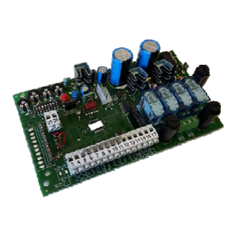
- Página 1 CENTRALE DI COMANDO AS24 Centralina di comando per 1-2 motori 24Vdc Guida per l’installazione...
- Página 2 1. Introduzione La centrale di comando AS24 è indicata per le installazioni a 1 o 2 ante battenti con motore a corrente continua 24V e un assorbimento massimo di 7A. Il quadro di comando permette una regolazione precisa della forza di spinta delle ante, della velocità e della sensibilità in fase di rallentamento, della velocità...
-
Página 3: Controlli Preliminari
4. Controlli preliminari Prima di dare alimentazione alla centrale, controllare tutti i cablaggi effettuati. In particolare controllare che non ci siano fili spellati, cortocircuiti tra fili e che tutti gli accessori siano collegati alla morsettiera nei punti indicati nello schema a pagina 1. Una volta data alimentazione verificare che: Il led POWER sia acceso fisso. - Página 4 6. Apprendimento corsa ante Questa procedura va effettuata SOLO dall’installatore e SOLO durante la messa in opera del sistema. Se non si utilizza un telecomando, è necessario utilizzare il tasto ROSSO (P1) e BLU (P2) presenti sulla scheda oppure con i pulsanti P.P e PED. Si deve quindi eseguire la procedura seguente. Chiudere il cancello, vedi punto 4 per muovere manualmente le ante.
- Página 5 8. Regolazione soglia sensore amperometrico in rallentamento Questa procedura va effettuata SOLO dall’installatore e SOLO durante la messa in opera del sistema. Per una corretta programmazione, prima di effettuare modifiche, riportare sempre il cancello in posizione totalmente chiusa. SLOW.DOWN. È possibile ruotare il trimmer SENS SLOW.DOWN.SENS in senso orario per aumen- Ripetere la misura...
- Página 6 10. Regolazione velocità motori in rallentamento Questa procedura va effettuata SOLO dall’installatore e SOLO durante la messa in opera del sistema. Per una corretta programmazione, prima di effettuare modifiche, riportare sempre il cancello in posizione totalmente chiusa. SLOW.DOWN. VELOCITY È possibile ruotare il trimmer SLOW.DOWN.VELOCITY.
- Página 7 12. Personalizzazione dell’apertura pedonale Questa procedura va effettuata SOLO dall’installatore e SOLO durante la messa in opera del sistema. Per una corretta programmazione, prima di effettuare modifiche, riportare sempre il cancello in posizione totalmente chiusa oppure con i pulsanti P.P e PED. Se non viene personalizzata, l’apertura pedonale corrisponde all’apertura totale della prima anta.
-
Página 8: Funzioni Avanzate
14.8 Impostazione del numero di ante La centralina AS24 è in grado di funzionare con i cancelli ad una o due ante. Questa impostazione viene effettuata posizionando il dip n° 8 so OFF se si vuole il funzionamento a due ante e su ON se si vuole il funzionamento ad un’anta singola. Questa impostazione DEVE essere eseguita prima dell’apprendimento delle corse. -
Página 9: Funzionamento Della Centralina
15. Modalità d’intervento delle fotocellule La modalità di intervento delle fotocellule è distinta: • Le fotocellule interne bloccano il movimento fino a rimozione dell’ostacolo, quindi comportano la riapertura completa del cancello. • Le fotocellule esterne non intervengono in apertura, mentre invertono immediatamente il moto fino alla riapertura completa nel caso di ostacolo in chiusura. -
Página 10: Risoluzione Problemi
19. Scheda aggiuntiva (non in dotazione) La centrale AS24 possiede un connettore (vedi schema pag.1) dove è possibile inserire una scheda aggiuntiva R2 per avere le uscite per il collegamento dell’elettroserratura e della luce di cortesia. Il tempo di accensione della luce di cortesia è di 1 min e 30 secondi. L’accensione avviene ad ogni operazione dell’utente. - Página 11 CONTROL UNIT AS24 Control unit for 1-2 motors 24Vdc Manual for installation...
-
Página 12: Configuration
1. Introduction The control unit AS24 is particularly indicated for the installation of 1 or 2 wing gates with motors with direct current 24V and a maximum absorption of 7A.The control unit allows a precise regulation of the thrust of the gates, of the velocity and sensitivity on slowing phase and of the velocity and sensitivity on the running phase. -
Página 13: Preliminary Checks
4. Preliminary checks Before connecting the control panel to the power supply, check all wirings which have been carried out. In particular check that there are no damaged wires, short-circuits between wires and that all accessories are connected to the terminal board in the points shown on the diagram on the previous page. - Página 14 6. Setting the wing stroke This procedure must ONLY be carried out by the installer and ONLY during the setting up of the system. If you do not utilize any transmitter, it is necessary to use the Red key (P1) and BLUE (P2) present on the card or with P.P and PED buttons. Then you must carry out the following procedure: Close the door, see point 4, to move the wings manually.
- Página 15 8. Adjusting threshold of the ampere sensor in slowing down This procedure must ONLY be carried out by the installer and ONLY during the put in function of the system. For a correct programming, before carrying out any modification, bring always back the door to the totally closed position. SLOW.DOWN.
- Página 16 10. Adjusting of the motors velocity in slowing down This procedure must ONLY be carried out by the installer and ONLY during the put in function of the system. For a correct programming, before carrying out any modification, bring always back the door to the totally closed position. SLOW.DOWN.
- Página 17 12. Personalization of pedestrian opening This procedure must ONLY be carried out by the installer and ONLY during the put in function of the system. For a correct programming, before carrying out any modification, bring always back the door to the totally close position. If not personalized, pedestrian opening corresponds to the total opening of first wing.
-
Página 18: Advanced Functions
14.8 Wings number setting The control unit AS24 can work with 1 or 2 wing gates. This setting is carried out putting the dip n° 8 on OFF if you want a 2 wing functioning and on ON if you want a single wing functioning. This setting MUST be carried out before the learning of the strokes. - Página 19 15. Modality of photocells intervention The modality of photocells intervention is different: The internal photocells unlock the movement until the obstacle is removed, so they involve the complete opening of the gate. • The external photocells do not intervene in opening, while they immediately invert the motion until the complete re opening in case of ob- •...
- Página 20 19. Additional card (not supplied as standard) The control unit AS24 has a connector (see diagram on page 1) where it is possible to insert an additional card in order to have the outputs for connection of the electric lock and the courtesy light. The lighting time of the courtesy light is fixed at 1 minute and 30 seconds. It lights for every operation of the user.
-
Página 21: Armoire De Commande As24
ARMOIRE DE COMMANDE AS24 Armoire de commande pour 1 - 2 moteurs 24Vdc Guide pour l’installation... - Página 22 1. Introduction La centrale de commande AS24 est indiquée pour les installations à 1 ou 2 moteurs à courant continu 24V et une absorption maximum de 7A. Le tableau de bord permet une régulation précise de la force de poussée, de la vitesse et de la sensibilité en phase de ralentissement, de la vitesse et de la sensibilité...
-
Página 23: Contrôles Préliminaires
4. Contrôles préliminaires Avant de donner alimentation à la centrale, contrôler tous les câblages effectués. En particulier, contrôler qu'il y n'ait pas fils écorchés, courts-circuits entre fils et que tous les accessoires soient branchés aux points indiqués dans le schéma à la page 1. Une fois alimenté le système, vérifier que: Le led POWER soit allumé... - Página 24 6. Apprentissage des courses Cette procédure doit être effectuée SEULEMENT par l'installateur et SEULEMENT pendant la mise en oeuvre du système. Si on n'utilise pas de télécommande, il est nécessaire d'utiliser la touche Rouge (P1) et BLEU (P2) présentent sur la fiche ou avec les boutons P.P et PED. Il faut exécuter ensuite la procédure suivante.
- Página 25 8. Régulation du seuil du capteur ampérométrique en ralentissement Cette procédure doit être effectuée SEULEMENT par l'installateur et SEULEMENT pendant la mise en œuvre du système. Pour une programmation correcte, avant d'effectuer des modifications reporter toujours l'automation en position totalement fermée. SLOW.DOWN.
- Página 26 10. Régulation vitesse moteur en ralentissement Cette procédure doit être effectuée SEULEMENT par l'installateur et SEULEMENT pendant la mise en œuvre du système. Pour une programmation correcte, avant d'effectuer des modifications reporter toujours l'automation en position totalement fermée. SLOW.DOWN. VELOCITY Il est possible de tourner le trimmer SLOW.
-
Página 27: Personnalisation De La Phase De Ralentissement
12. Personnalisation de l'ouverture piéton (ouverture partielle) Cette procédure doit être effectuée SEULEMENT par l'installateur et SEULEMENT pendant la mise en œuvre du système. Pour une programmation correcte, avant d'effectuer des modifications reporter toujours l'automation en position totalement fermée. Si elle n'est pas personnalisée, l'ouverture piéton correspond à... -
Página 28: Fonctions Avancées
14.8 Réglage du nombre de battant La centrale AS24 è capable de fonctionner avec des portails à 1 ou 2 battants. Ce réglage est effectué en plaçant le il dip n° 8 sur OFF si on désire le fonctionnement à deux battants et sur ON si on désire le fonctionnement à 1 battant. Ce réglage DOIT être fait avant d’effectuer la phase d’apprentissage des courses. -
Página 29: Fonctionnement De La Centrale
15. Modalité d'intervention des photocellules La modalité d’intervention des photocellules est différencié: Les photocellule interne bloquent le mouvement tant que l’obstacle est présent, après quoi, comporte la réouverture complète de l’automation • Les photocellule externe n'interviennent pas en ouverture, pendant qu'ils inversent immédiatement le mouvement jusqu'à... -
Página 30: Résolution Des Problèmes
19. Carte supplémentaire (pas en dotation) La carte AS24 à un connecteur (voir schéma page 1) où il est possible insérer une carte additionnelle pour avoir les sorties pour le branchement de l’électroserrure et de la minuterie d’éclairage. Le temps d’allumage de la minuterie d’éclairage est fixé à 1 min et 30 secondes. -
Página 31: Cuadro De Mando As24
CUADRO DE MANDO AS24 Cuadro de mando para 1-2 motores 24Vdc Guía para la instalación... -
Página 32: Introducción
1. Introducción El cuadro de control AS24 es especialmente indicado para las instalaciones de puertas de 1 o 2 hojas con motor de corriente continua 24V y con absorción máxima de 7A. El cuadro de control permite una regulación precisa de la fuerza de empuje de las hojas, de la velocidad y de la sensibilidad en fase de ralentización, de la velocidad y de la sensibilidad a régimen. -
Página 33: Controles Preliminares
4. Controles preliminares Antes de conectar el cuadro a la corriente, comprobar todos los cableados realizados. En particular comprobar que no hayan cables pelados, cortocircuitos entre hilos y que todos los accesorios sean conectados a a regleta de bornes en los puntos que indica el esquema de la página 1. Una vez conectada la alimentación verificar que: El led POWER se enciende permanente/fijo. -
Página 34: Atencion: Durante El Aprendizaje Del Recorrido Se Regula También El Desfase De Las Hojas
6. Aprendizaje recorrido hoja. Este procedimiento debe ser efectuado SOLO por el instalador y SOLAMENTE durante la puesta en funcionamiento del sistema. Si no se utiliza un emisor, es necesario utilizar la tecla Roja (P1) y Azul (P2) presentes en la tarjeta, o bien con los pulsadores P.P y PED. A este punto, se debe realizar el siguiente procedimiento. -
Página 35: Regulación Umbral Sensor Amperométrico En Ralentización
8. Regulación umbral sensor amperométrico en ralentización Este procedimiento debe ser realizada SOLO por el instalador y SOLO durante la puesta en funcionamiento del sistema. Para una correcta programación, antes de hacer modificaciones, llevar siempre la puerta en posición totalmente cerrada. SLOW.DOWN. - Página 36 10. Regulación velocidad motores en ralenti- Este procedimiento debe ser realizado SOLO por el instalador y SOLO durante la puesta en funcionamiento del sistema. Para una correcta programación, antes de hacer modificaciones, llevar siempre la puerta en posición totalmente cerrada. SLOW.DOWN.
-
Página 37: Personalización De La Fase De Ralentización
12. Personalización de la apertura peatonal. Este procedimiento debe ser efectuado SOLO por el instalador y SOLO durante la puesta en funcionamiento del sistema. Para una correcta programación, antes de efectuar modificaciones, llevar siempre la puerta en la posición totalmente cerrada o bien con los pulsadores P.P y PED. Si no ha sido personalizada la apertura peatonal corresponde a la apertura total de la primera hoja. -
Página 38: Funciones Avanzadas
14.8 Regulación del número de hojas El cuadro AS24 puede funcionar con las puertas de una o dos hojas. Esta regulación se realiza posicionando el dip n° 8 en OFF si se quiere el funcionamiento con dos hojas y en ON si se quiere el funcionamiento de una hoja individual. Esta regulación DEBE ser realizada antes del aprendizaje del recorrido. -
Página 39: Modalidad De Intervención De Las Fotocélulas
15. Modalidad de intervención de las fotocélulas La modalidad de intervención de las fotocélulas es distinta: Las fotocélulas internas blocan el movimiento hasta que se elimine el obstáculo, por lo tanto realizan la apertura completa de la puerta. • Las fotocélulas externas no funcionan en apertura, mientras invierte immediatamente el movimiento hasta la apertura completa en el caso •... -
Página 40: Solución De Problemas
19. Tarjeta adicional (no en dotación) El cuadro AS24 tiene un conector (ver esquema pág.1) donde es posible enchufar una tarjeta adicional R2 para tener las salidas para la conexión de la cerradura eléctrica y de la luz de cortesía. El tiempo de encendido de la luz de cortesía es de 1 min y 30 segundos. El encendido se realiza con cada operación del usuario. - Página 41 STEUERUNGSPLATINE AS24 Steuerungsplatine für 1-2 Motoren 24Vdc Installationsanleitung...
- Página 42 1. Einleitung Die Steuerung AS24 ist für den Betrieb von 1 oder 2 Fluegeltöre mit 24V Gleichstrommotoren und eine max Aufnahme von 7A geeignet. Die Schalttafel erlaubt eine präzise Regulierung des Flügelskraftschubes, der Geschwindlichkeit und der Empfindlichkeit in der Abnahmenphase, und der Geschwindigkeit und Empfindlichkeit während das Betrieb.
- Página 43 4. VORKONTROLLEN Bevor Speisung an die Platine geben, kontrollieren Sie bitte alle Verkabelungen. Besondersweise kontrollieren Sie bitte, daß es keine abhänteten Kabel, Kabelkurzschluesse sind, und daß alle Zubehöre an den Klammer -wie im Schema auf Seite 1-, verbunden sind . Nach Speisung prüfen Sie bitte: POWER Led ist fix eingeschaltet.
- Página 44 6. Torlauflernung Diese Prozedur muss NUR beim Installateur durchegeführt werden und NUR beim System Setzung im Betrieb. Falls kein Handsender benützt worden ist, ist es nötig ROTE- (P1) und BLAUE Taste (P2) auf der Platine oder mit P.P und PED Tasten benützen. Man muss dann folgendes Prozedur ausführen.
- Página 45 8. Regulierung von Strommessersensorschwelle im Verlangsamung Diese Prozedur muss NUR beim Installateur durchgeführt und NUR während System Setzung im Betrieb. Um eine korrekte Programmierung, bevor Änderungen durchzuführen, tragen Sie Gitter immer in Position total geschlossen. SLOW.DOWN. Es ist möglich Trimmer SLOW.DOWN.SENS im SENS Uhrzeigersinn umlaufen, um die Schwelle von Wiederholen Sie...
- Página 46 10. Regulierung von Motorgeschwindlichkeit in Verlangsamungsphase Diese Prozedur muss NUR beim Installateur durchgefuehrt und NUR während System Setzung im Betrieb. Um eine korrekte Programmierung, bevor Änderungen durchzuführen, tragen Sie Gitter immer in Position total geschlossen. SLOW.DOWN. VELOCITY Es ist möglich Trimmer SLOW. DOWN. VELOCI- TY im Uhrzeigersinn umlaufen, um Motorgesch- windlickeit zu erhöhen Geschwindlickeit ist zu niedrig...
- Página 47 Personalisierung der Fußgängeröffnung Diese Prozedur muss NUR beim Installateur durchgeführt und NUR während System Setzung im Betrieb. Um eine korrekte Programmierung, bevor Änderungen durchzuführen, tragen Sie Gitter immer in Position total geschlossen oder mit Tasten P.P und PED. Wenn nicht personalisiert, Fußgängeröffnung entspricht dem total Öffnung des ersten Flügels.
-
Página 48: Erweiterte Einstellungen
Kontakt öffnet sich, Gitter schliesst sich automatisch. 14.8 Flügelnummeransatz Die Steuerung AS24 kann mit Einfluegel– oder Zweifluegelgitter arbeiten. Dieser Ansatz ist aktiviert beim Positionieren dip n° 8 auf OFF für Zweiflügelfunktion und auf ON fuer Einflügelfunktion. Dieser Ansatz MUSS bevor Lauflernung durchgeführt werden. - Página 49 15. Eingriffweise der Photozellen Eingriffsweise von Photozellen ist getrennt: Innere Photozellen stoppen die Bewegung bis zum Hindernissbeseitigung, d.h. Sie öffnen Gitter wieder. • Äussere Photozellen arbeiten bei Öffnung nicht, aber die umkehren sofort die Bewegung bis zum komplette Wiederöffunung im Falle von •...
-
Página 50: Problemlösung
19. Zusatzplatine (nicht ausgerüstet) Die Steuerung AS24 hat einen Verbinder (sehen Sie Schema Seite.1) wo es möglich ist, eine Zusatzplatine R2 einzuführen. Das gibt die Möglichkeit Ausgänge für Verbindung mit Elektroschloss und Höflichkeitlicht zu haben. Zuendungszeit der Höflichkeitlicht ist 1 min und 30 Sek.