
Manuales relacionados para Megger DET5/4R


Resumen de contenidos para Megger DET5/4R
- Página 1 DET5/4R & DET5/4D Digital Earth Testers USER GUIDE GUIDE DE L’UTILISATEUR GEBRAUCHSANLEITUNG GUÍA DEL USUARIO...
-
Página 2: Safety Warnings
• Replacement fuses must be of the correct type and rating • Before charging the DET5/4R battery ensure that the correct supply fuse is fitted and the voltage selector is set correctly. • Warnings and precautions must be read and understood before the instrument is used. They must be observed during use. -
Página 3: Tabla De Contenido
General Testing Procedure Repair and Warranty Display symbols Setting-up the test spikes etc. Guide de l’utilisateur Basic test procedure Gebrauchsanleitung Battery charging (DET5/4R) Fitting or replacing the battery cells (DET 5/4D) Guía del usuario MEASURING TECHNIQUES Testing earth electrodes Fall-of-Potential method... -
Página 4: Illustrations
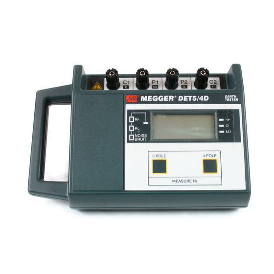
Illustrations Fig.1 DET5/4 Features and controls Fig.12 Resistance curve from Slope method Fig.2 A method of connection where fault tests conditions may occur Fig.13 Possible results from several Slope Fig.3 Low battery voltage indication method tests Fig.4 High Current spike resistance warning Fig.14 ‘Dead’... -
Página 5: General Description
This kit current circuit test leads does not affect the result. also includes test spikes (electrodes) for making In the DET5/4R and DET5/4D the resistance of the temporary earth spikes. Potential circuit test leads can also be ignored because... - Página 6 GENERAL DESCRIPTION decimal point automatically positioned. It also gives an over-range indication if the resistance under test exceeds 20 kΩ. This instruments has been designed to comply with the performance specifications of BS7430 (formerly CP 1013 from BSI), BS7671 (IEE Wiring Regulations) IEC 364, NFC 15-100 French Specification and VDE 0413 Part 7 (1982) German specification.
-
Página 7: Applications
The primary application of the DET5/4R and moisture conditions, (e.g. brought about by changing DET5/4D is in the testing of earth electrodes, whether weather conditions or different seasons of the year). -
Página 8: Features And Controls
To electrode under test (4 terminal test) To Potential test spike (3 terminal test) To Current test spike Battery compartment (and charger socket cover DET5/4R) ⁄ digit L.C.D. Low Battery indicator point Ω and kΩ range indicator points Low Battery and Range indicator... -
Página 9: Live Earth Safety Precautions
Fault working near high tension systems where any Isolation current unintentional ‘Live' earths may be encountered ® EARTH EARTH MEGGER MEGGER DET5/4D DET5/4D TESTER TESTER switches between the site earth and remote earths established Remote... -
Página 10: Operation
CIRCUIT CONDITION WARNING INDICATORS Warning LED’s to the left of the display will indicate any It is advisable that the battery of the DET5/4R is excessive resistance in the Current circuit or Potential fully charged before embarking on a test circuit, and any excessive electrical ‘Noise’... -
Página 11: Fig.4 High Current Spike Resistance Warning
High Current Spike Resistance (Rc) the soil near the electrode under test and / or the During a test, if the resistance of the Current circuit is remote Potential spike. Whatever causes the condition too high for accurate measurement, the Rc LED warning to appear should be cleared before a test can automatically illuminates, accompanied by the warning be regarded as valid. -
Página 12: Setting-Up The Test Spikes Etc
OPERATION SETTING UP THE TEST SPIKES ETC. and the solution may be to wait until the interference has subsided. Alternatively, choose a new position for For earth electrode testing and for earth resistivity the two remote test spikes, by re-siting them at right surveying, the instrument’s test leads are connected to angles to their first position;... -
Página 13: Basic Test Procedure
BASIC TEST PROCEDURE the instrument has commenced its test sequence. Four Terminal Measurement Once the button has been released, the test will After the test spikes have been set up and connected continue for approximately 30 seconds. to the instrument for the type of test to be carried out To switch the instrument ‘Off’... -
Página 14: Battery Charging (Det5/4R)
OPERATION BATTERY CHARGING (DET5/4R) It is advisable that the battery of the DET5/4R is fully When the fuse and voltage selector are correctly set, charged before embarking on a test sequence. It is plug the mains supply lead into a suitable socket outlet beneficial to the battery to keep it fully charged. -
Página 15: Measuring Techniques Testing Earth Electrodes
Insert the Current test spike into the ground some 30 to 50 metres away from the earth electrode to be tested. ® EARTH EARTH MEGGER MEGGER DET5/4D DET5/4D TESTER TESTER Firmly connect this spike to the instrument terminal 'C2'. -
Página 16: The 61,8% Rule
ONLY be done if the test lead can be kept short because its resistance will be included in the measurement. EARTH EARTH ® MEGGER MEGGER DET5/4D DET5/4D TESTER TESTER 3 POLE 4 POLE MEASURE R Note:- Earth electrode test lead resistance can be determined separately. -
Página 17: Electrode And Current Spike
Potential spike under test spike Fig 9. Resistance areas associated with an earth electrode and current spike. ® EARTH EARTH MEGGER MEGGER DET5/4D DET5/4D TESTER TESTER Theoretically, both the Current and Potential spikes 3 POLE 4 POLE should be at an infinite distance from the earth MEASURE R electrode. -
Página 18: The Slope Method
(Remember that the Potential spike must also be moved in ® EARTH EARTH TESTER TESTER MEGGER MEGGER DET5/4D DET5/4D 3 POLE 4 POLE accordance with the 61,8% Rule). The average of the MEASURE R three readings can then be calculated. -
Página 19: Fig.12 Resistance Curve From Slope Method
The earth resistance is measured at each separate Calculate the slope coefficient µ, where position of the Potential spike and the resistance curve is plotted from the results. At least six readings are µ = ( R3-R2 ) (R2-R1) needed. The diagram of Fig. 12 shows an example. Drawing the curve will show up any incorrect points which may be either rechecked or ignored. -
Página 20: Tests
MEASURING TECHNIQUES Testing Earth Electrodes another curve can be plotted, as shown in Fig. 13 for example. Fig.13 Possible results from several Slope method tests. This shows how the resistance is decreasing as the distance chosen for EC is increased. The curve indicates that the distances chosen for EC in tests (1) and (2) were not large enough, and that those chosen in tests (3) and (4) were preferable because... -
Página 21: Method Using 'Dead' Earth
METHOD USING A ‘DEAD’ EARTH the earth electrode and the ‘dead’ earth. The techniques using test spikes explained earlier are the preferred methods of earth testing. In congested areas it may not be possible to find suitable sites for the test spikes, nor sufficient space to run the test leads. -
Página 22: Bs7671 (16Th Edition Iee Wiring Regulations) Requirements
There are other methods of earth electrode testing Regulation 713-11 of BS7671 specifies that the among which are the Four Potential, Intersecting Curves and Star Delta methods. Megger Limited have produced resistance of earth electrodes must be measured. The accompanying Guidance Notes describe a method of a book entitled ‘A Simple Guide to Earth Testing’... -
Página 23: Determining 'Touch' Potential
DETERMINING ‘TOUCH’ POTENTIAL ‘Touch’ potential is the potential difference a person would experience across his body if he were, for example, standing on the ground outside the earthed perimeter fence of a substation and touching the fence Earthed Perimeter Fence at the time a fault occurred. -
Página 24: Determining 'Step' Potential
MEASURING TECHNIQUES Testing Earth Electrodes DETERMINING ‘STEP’ POTENTIAL ‘Step’ potential is the potential difference a person would experience between his feet as he walked across the ground in which a fault current was flowing. Earthed Perimeter Fence Firmly connect the instrument as follows :- SUBSTATION Terminal 'C1' to the substation earth. -
Página 25: Typical Variations In Soil Resistivity
MEASURING TECHNIQUES Measuring Soil Resistivity TYPICAL VARIATIONS IN SOIL RESISTIVITY first laid down and thereafter at periodic intervals. The resistance to earth of an earth electrode is Before sinking an electrode into the ground for a new influenced by the resistivity of the surrounding soil. The installation it is often advantageous to make a resistivity depends upon the nature of the soil and its preliminary survey of the soil resistivity of the... -
Página 26: Line Traverse
By this means depth surveys may be made. More details can be found in the Megger Limited publication ‘A Simple Guide to Earth Testing’ (Part Number 6171-230). -
Página 27: Calculation Of Resistivity
CALCULATION OF RESISTIVITY Assuming that the tests were carried out in homogeneous soil the resistivity is given by the formula:- ρ ρ = 2πaR where ‘R’ is the resistance measured in ohms, ‘a’ is the test spike spacing in metres and ‘ρ ρ ’ is the resistivity in ohm-metres. -
Página 28: Continuity Testing
4 pole tester, or connected as shown in Fig. 20. Ensure that the circuit is de- energised, before connecting the instrument for measurement. ® EARTH EARTH MEGGER MEGGER DET5/4D DET5/4D TESTER TESTER Note:- Due to the inherent high accuracy of the... -
Página 29: Circuit Description
CIRCUIT DESCRIPTION The instrument uses the four terminal method of measurement. A reversing d.c. test current is injected into the earth through terminals ‘C1’ and ‘C2’. The High Current Control logic potential developed across the earth is monitored with loop resistance ‘P1’... -
Página 30: Specifications
SPECIFICATION Earth Resistance Ranges: 0,01 Ω to 19,99 Ω 0,1 Ω to 199,9 Ω 1 Ω to 1,999 kΩ 10 Ω to 19,99 kΩ Accuracy (23°C ±2°C): ±7.5% ±3 digits (±10% at >0.5 ohms and ±0.05 ohm at <0.5 ohms for KEMA K85B requirements. - Página 31 These are loop resistances, therefore the resistance under test must be subtracted from these figures. If the ‘Rc’ indicator is not showing, the maximum error will not exceed 2%. Max. Potential Spike Resistance: An additional error (typically 1%) will be introduced by a Potential spike resistance of 75 kΩ.
- Página 32 Power Supply: Internal rechargeable sealed lead acid cells 12 V, 0,8 Ah capacity. Battery voltage range over which basic DET5/4R: accuracy is maintained, 10,0 V to 13,5 V. Battery life; 600 x 15 s tests Battery charging time, 10 hours max. (from completely exhausted).
- Página 33 Dimensions: 240 mm x 160 mm x 70 mm (9,4 in x 6,3 in x 2,75 in approx.) Weight: DET5/4R:1,27 kg (2,8 lb approx.) DET5/4D:0,82 kg (1.5 lb approx.) Cleaning: Wipe the disconnected instrument with a clean cloth dampened with soapy water or Isopropyl Alcohol (IPA)
-
Página 34: Accessories
6172-132 Standard Accessory kit 250579 Shorting bars (x2) 5131-365 Canvas case containing:- Power cord (for battery 2 x 20 in rods, leads charging DET5/4R) (25,50 &100 ft) OPTIONAL Instrument carrying harness 6220 - 537 Deluxe Accessory kit 250581 Carrying Case... -
Página 35: Chart For Use With Slope Method
Chart for use with the Slope Method Values of P t / EC for Values of µ µ 0.40 0.6432 0.6431 0.6429 0.6428 0.6427 0.6425 0.6424 0.6422 0.6421 0.642 0.41 0.6418 0.6417 0.6415 0.6414 0.6412 0.6411 0.641 0.6408 0.6407 0.6405 0.42 0.6404 0.6403... - Página 36 Chart for use with the Slope Method (continued) µ 0.64 0.6072 0.6071 0.6069 0.6068 0.6066 0.6064 0.6063 0.6061 0.606 0.6058 0.65 0.6056 0.6055 0.6053 0.6052 0.605 0.6048 0.6047 0.6045 0.6043 0.6042 0.66 0.604 0.6039 0.6037 0.6035 0.6034 0.6032 0.6031 0.6029 0.6027 0.6026 0.67...
- Página 37 µ 0.90 0.5618 0.5616 0.5614 0.5612 0.561 0.5608 0.5606 0.5604 0.5602 0.56 0.91 0.5598 0.5596 0.5595 0.5593 0.5591 0.5589 0.5587 0.5585 0.5583 0.5581 0.92 0.5579 0.5577 0.5575 0.5573 0.5571 0.5569 0.5567 0.5565 0.5563 0.5561 0.93 0.5559 0.5557 0.5555 0.5553 0.5551 0.5549 0.5547 0.5545...
- Página 38 Chart for use with the Slope Method (continued) µ 1.16 0.5046 0.5043 0.5041 0.5038 0.5036 0.5033 0.5031 0.5028 0.5025 0.5023 1.17 0.502 0.5018 0.5015 0.5013 0.501 0.5007 0.5005 0.5002 0.4997 1.18 0.4994 0.4992 0.4989 0.4987 0.4984 0.4981 0.4979 0.4976 0.4973 0.4971 1.19 0.4968...
- Página 39 µ 1.42 0.4232 0.4228 0.4225 0.4221 0.4217 0.4213 0.4209 0.4205 0.4201 0.4197 1.43 0.4193 0.4189 0.4185 0.4181 0.4177 0.4173 0.4168 0.4164 0.416 0.4156 1.44 0.4152 0.4148 0.4144 0.414 0.4136 0.4131 0.4127 0.4123 0.4119 0.4115 1.45 0.4111 0.4106 0.4102 0.4098 0.4094 0.409 0.4085 0.4081...
-
Página 40: Repair And Warranty
A number of independent instrument repair severe transport stresses. companies have been approved for repair work on most Megger instruments, using genuine Megger spare parts. New Instruments are Guaranteed for 3 Years from the Consult the Appointed Distributor/Agent regarding spare Date of Purchase by the User. -
Página 42: Consignes De Securite
S'assurer que les fusibles de rechange sont du type prévu et ont un pouvoir de coupure correct. Avant de recharger la batterie DET5/4R, s'assurer que le fusible d'alimentation correct est en position et que le sélecteur de tension occupe la plage correcte. - Página 43 à la terre à distance installées pour effectuer les essais. Une mise à la terre "sous tension" achemine du Courant courant depuis l'alimentation secteur ou risque de le de défaut EARTH EARTH ® MEGGER MEGGER DET5/4D DET5/4D TESTER TESTER faire en présence d'une anomalie. 3 POLE...
- Página 44 Il est recommandé de bien charger la batterie de à la tension maximale de défaut. Consulter à ce titre la DET5/4R avant d'effectuer une série d'essais. En Section intulée “Procédure d;essai de Base”. effet, si la charge de la batterie devient trop faible Procedure Generale D’essai...
- Página 45 lors d'un test puisse être considéré comme valide. Pour résoudre ce problème, il est possible de verser de l'eau sur le sol à proximité de la sonde de courant, de déplacer cette sonde ou d'utiliser plusieurs sondes. Fig. 2 indication d'une tension insuffisante de la batterie ou des piles Temoins Lumineux des Conditions des Circuits Les LED à...
- Página 46 vérifiée qu'au début d'un essai et ne constitue pas un Inversion de Polarite processus réalisé en continu. Pour revérifier cette Lorsque les conducteurs de potentiel sont inversés par résistance, il faut appuyer sur le bouton-poussoir rapport aux conducteurs de courant, l'écran clignote approprié...
- Página 47 à la plage de courant inférieure qui peut tolérer une ® EARTH EARTH TESTER MEGGER MEGGER DET5/4D DET5/4D TESTER résistance plus élevée de la sonde de courant. 3 POLE 4 POLE Cela entraîne cependant une perte de résolution.
-
Página 48: Recharge De La Batterie (Det5/4R)
Il est recommandé de bien recharger la batterie de celles des mesures à 4 bornes, si ce n'est qu'il faut l'instrument DET5/4R avant d'effectuer une séquence appuyer sur le bouton-poussoir 3 pole pour faire d'essai. Il est également avantageux de maintenir cette fonctionner cet instrument. - Página 49 suffit d'inverser la position du porte-fusible dans cette qui doit rester inutilisé pendant des périodes prolongées. prise. Lorsque le fusible et le sélecteur de tension sont corrects, brancher le conducteur d'alimentation secteur sur une prise femelle appropriée et mettre le circuit sous tension. Une LED s'allume au niveau de l'entrée de l'alimentation secteur portant la référence "CHARGE"...
-
Página 50: Accessoires Fournis
ACCESSOIRES FOURNIS NUMERO DE REFERENCE Guide Utilisateur 6172-132 2 barres de court-circuit 5131-365 Cordon électrique(pour recharge de batterie DET5/4R) EN OPTION Harnais de transport de l'instrument 6220-537 Coffret de transport 6231-585 Trousse d'essai de mise à la terre à quatre bornes... -
Página 51: Réparation Et Garantie
Réparation d’instruments et pièces de rechange imprimes. Si la protection d’un instrument s’est trouvee Pour le service des instruments Megger prendre affectée de quelque maniére il ne doit pas être utilisé et contact soit: doit être expeedié... -
Página 52: Gebrauchsanleitung
• Es müssen Ersatzsicherungen der richtigen Nennleistung installiert werden. • Achten Sie vor dem Aufladen der DET5/4R-Batterie darauf, daß die richtige Versorgungssicherung angebracht und der Spannungswähler auf die richtige Spannung eingestellt ist. • Vor Gebrauch des Instruments müssen Sie die Vorsichtsmaßnahmen lesen und verstehen. Sie sind während des Gebrauchs zu beachten. - Página 53 Arbeiten in der Nähe von Hochspannungsanlagen schalter unbedingt erforderlich, wenn unbeabsichtigt Fehlerstrom entfernt ® EARTH EARTH spannungsführende Erdungsleitungen zwischen der MEGGER MEGGER DET5/4D DET5/4D TESTER TESTER angebrachte Anlage und der Erdung von Nebenstationen für 3 POLE 4 POLE MEASURE R Prüfstäbe Prüfzwecke...
- Página 54 Falls Bedingungen für Prüfung zufriedenstellend sind, stabilisiert sich Leuchtanzeige und die angezeigten Werte können akzeptiert werden. Es empfiehlt sich, beim Arbeiten mit dem DET5/4R vor Beginn einer Prüfsequenz darauf Fig.2 Batteriespannungsanzeige zu achten, daß die Batterie voll aufgeladen ist. Es...
- Página 55 STROMKREIS-WARNANZEIGEN Verwendung von mehr als einem Stab gelöst werden. Prüfstab für Hochspannungswiderstand (Rp) Die Warnanzeigen auf der linken Seite der Bildanzeige Um anzuzeigen, daß der Widerstand des Stromkreises zeigen an, daß der Widerstand des Stromkreises oder zu hoch für eine genaue Messung ist, leuchtet der Spannungssonde und das elektrische 'Rauschen' automatisch die Rp-Leuchtanzeige zusammen mit der zu hoch ist.
- Página 56 Betrieb Fig.5 Anzeige für Polaritätsumkehrung Fig.4 Warnanzeige für übermäßige Rauschstörung Einrchtung Der Prüfstabe USW Unter solchen Bedingungen kann keine Messung Für die Prüfung von Elektroden und die Überwchung vorgenommen, vielmehr muß abgewartet werden bis des Erdwiderstands werden die Prüfkabel des die Störung sich abschwächt.
- Página 57 Strombereich ein, der einen höheren Stromabwiderstand verarbeiten kann. Dies führt zu einem Auflösungsverlust. ® EARTH EARTH TESTER TESTER MEGGER MEGGER DET5/4D DET5/4D Die Taste kann zu jedem Zeitpunkt losgelassen 3 POLE 4 POLE MEASURE R werden, nachdem das Instrument die Prüfsequenz Fig.5 Messung mit vier Anschlüssen...
- Página 58 Betrieb Messung mit drei Anschlüssen BATTERIELADUNG (DET5/4R) Bei diesem Prüfverfahren handelt es sich im Es ist ratsam, die Batterie des DET5/4R vor Beginn wesentlichen um dasselbe Verfahren wie bei der einer Prüfsequenz vollständig aufzuladen. Messung mit vier Anschlüssen, jedoch mit der Haltbarkeit der Batterie profitiert von der vollständigen...
- Página 59 Stecken Sie nach korrekter Einstellung von Sicherung EINSETZEN ODER AUSWECHSELN BATTERIEN (DET5/4D) und Spannungswähler den Neztzstecker in eine geeignete Netzsteckdose und schalten Sie das Gerät Achtung: Verwenden Sie nur Batterien des richtigen ein. Daraufhin erscheint neben der Stromversorgung Typs (Alkali IEC LR6). eine Leuchtanzeige mit der Markierung 'CHARGE', wodurch angezeigt wird, daß...
-
Página 60: Auf Wunsch Lieferbar
Zubehör MITGELIEFERT ZUBEHÖRNUMMER Gebrauchsanietung 6172-532 Erdshlußstäbe 5131-365 Netzkabel (für Batterieaufladung DET5/4R) AUF WUNSCH LIEFERBAR Tragegurt für das Instrument 6220-537 Trageghäuse 6231-585 Erdungsprüfkasten mit 4 Anschlüssen 6310-755 bestehend aus einer Tragetasche inklusive:- Fäustel, 4 Prüfstäbe aus galvanisiertem Stahl 12 mm stark (quadratsich) x 450 mm lang. -
Página 61: Reparaturen Und Garantie
Beschädigung, fehlende Anzeige der erwarteten Eine Reihe von Firmen sind für die Reparatur der Meßergebnisse; längere Lagerung unter widrigen meisten Megger - lnstrumente unter Verwendung von Bedingungen oder starke Transportbelastung. Original Megger -Ersatzteilen autorisiert. Wenden Sie NEUE INSTRUMENTE UNTERLIEGEN EINER GARANTIE... -
Página 62: Normas De Seguridad
NORMAS DE SEGURIDAD En instalaciones donde exista la posibilidad de que hayan tierras bajo tensión, se deben tomar medidas de precaución especiales y emplear interruptores y fusibles de aislamiento. Véase la página 63 para más información. Mientras el instrumento esté encendido, no deben tocarse las picas de tierra ni los cables de prueba y sus terminales. -
Página 63: Operación
Corriente por una mala instalación o por una condición de fallo. del fallo EARTH EARTH ® MEGGER MEGGER DET5/4D DET5/4D TESTER TESTER Picas de prueba Todas las personas encargadas de realizar este... -
Página 64: Procedimiento General Para La Realización De Pruebas
Antes de proceder con la secuencia de prueba, se PROCEDIMIENTO GENERAL PARA LA recomienda instalar en el probador DET5/4R una REALIZACIÓN DE PRUEBAS pila completamente cargada. Esta medida de Conecte y asegure firmemente los terminales del precaución evita los innumerables inconvenientes... -
Página 65: Indicadores De Aviso De La Condición Del Circuito
En cualquier caso, la condición de aviso debe corregirse antes de realizar la prueba. El problema puede deben volver a cargar (DET5/4R), o sustituir (DET5/4D), para poder seguir realizando las pruebas. Fig. 2 Indicación de voltaje bajo de las pilas solucionarse humedeciendo el área alrededor de la... -
Página 66: Polaridad Invertida
OPERACIÓN la pica o usando varias picas. Téngase en cuenta que POLARIDAD INVERTIDA la resistencia de la pica de potencial sólo se Si la polaridad de los cables de potencial está invertida comprueba al momento de iniciar la prueba y no es un con respecto a los cables de corriente, la pantalla proceso que se ejecuta continuamente. -
Página 67: Procedimiento Básico Para La Realización De Pruebas
® EARTH EARTH MEGGER MEGGER DET5/4D DET5/4D TESTER TESTER El pulsador puede liberarse en cualquier momento 3 POLE... -
Página 68: Carga De Las Pilas (Det5/4R)
Antes de proceder con la secuencia de prueba, se prueba es el mismo que se utiliza para la medición de recomienda instalar en el probador DET5/4R una pila cuatro terminales, excepto que hay que pulsar el botón completamente cargada. Esta medida de precaución 3 pole. -
Página 69: Instalación O Reemplazo De Las Pilas
portafusible en la toma. INSTALACIÓN O REEMPLAZO DE LAS PILAS (DET5/3D) Cuando el tipo fusible y la posición del selector de voltaje sean adecuados, enchufe el cable de Precaución:- Utilice únicamente pilas alcalinas IEC alimentación y encienda el instrumento. Se enciende el LR6. -
Página 70: Accesorios
ACCESORIOS INCLUIDOS NÚMERO DE PIEZA Guía del Usuario 6172-132 Barras de acortamiento (x2) 5131-365 Cable de alimentación (para cargar la pila DET5/4R) OPCIONAL 6220-537 Arnés de transporte 6231-585 Estuche 6310-755 Kit de la prueba de tierra de 4 terminales Bolsa que contiene:- Martillo de porra, 4 picas de acero galvanizado de 12 mm calibre x 450 mm de longitud;... -
Página 71: Reparacione Y Garantia
Reparación de Instrumentos y Piezas de Repuesto dirección adecuada. Al mismo tiempo, deberá Para un servicio de los instrumentos Megger contacte adjuntarse una copia de la factura y de la nota de por favor con: envío, por correo aéreo, a fin de acelerar los trámites... - Página 72 OTHER TECHNICAL SALES OFFICES Toronto CANADA, Sydney AUSTRALIA, Madrid SPAIN, Mumbai INDIA and the Kingdom of BAHRAIN. Megger products are distributed in 146 countries worldwide. This instrument is manufactured in the United Kingdom. The company reserves the right to change the specification or design without prior notice.