
Manuales relacionados para STAMOS MIG Serie


Resumen de contenidos para STAMOS MIG Serie
- Página 1 BEDIENUNGSANLEITUNG MIG MAG MMA S - M I G 2 5 0 C S - M I G 3 5 0 C W W W. S T A M O S - W E L D I N G . C O M...
-
Página 2: Allgemeine Sicherheitshinweise
INHALT | CONTENT | CONTENU | CONTENIDO | TREŚĆ Herzlichen Glückwunsch zum Kauf des aktuellen MIG/MAG/MMA Schweißgerät von Stamos Germany. Bitte lesen Sie die Anleitung aufmerksam um jederzeit die bestmöglichen Ergebnisse mit Ihrem neuen Schweißgerät zu erzielen. ALLGEMEINE SICHERHEITSHINWEISE Gerät Die Schweißgeräte für das manuelle Schutzgasschweißen mit automatischem Draht-... -
Página 3: Verhalten Im Notfall
Bediener und weitere Personen Verbote Offenes Feuer Da beim Schweißprozess Strahlen und Hitze entstehen, ist sicherzustellen, dass ent- sprechende Mittel angewandt und Schutzmaßnahmen für die eigene Person und für Offenes Licht Drittpersonen ergriffen werden. Rauchen Warnungen gefährliche elektrische Spannungen Stolpergefahr Setzen Sie sich und andere Personen niemals ohne Schutz den Auswirkungen des Lichtbogens oder des glühenden Metalls aus. -
Página 4: Vor Der Ersten Benutzung
Mindestalter: Das Gerät darf nur von Personen betrieben werden, die das Gefährdung Beschreibung Schutzmaßnahme 18. Lebensjahr vollendet haben. Eine Ausnahme stellt die Be- Durchstich / Hände können durch den Schutzhandschuhe tra- nutzung als Jugendlicher dar, wenn die Benutzung im Zuge Einstich Draht durchstochen werden gen und Hände vom... - Página 5 AUFBAU UND ANSCHLUSS Netzanschlussplan Die gelb-grüne Ader ist für den Schutzlei- Aufbau- und Anschlussplan teranschluss PE vorgesehen. Die drei Phasen (schwarz, braun und blau) können beliebig an L1, L2 und L3 angeschlossen werden. Bitte lassen Sie diese Arbeiten nur von einer qua- lifizierten Elektrofachkraft ausführen lassen).
- Página 6 Bedienpanel Drehknopf In- Einstellen der Induktivität (Beeinflussung duktivität der Schweißstabilität, Schmelztiefe und Taste Drahtvor- Manueller Drahtvorschub zum Einfädeln Spritzermenge) schub Drehknopf Einstellen des Schweißstroms (MMA) 2T/4T - Wipp- Wechsel zwischen Sperrfunktion/keine Schweißstrom schalter Sperrfunktion Funktions - Wechseln zwischen MIG und MMA Drehknopf Einstellen des Schweißstroms Wippschalter...
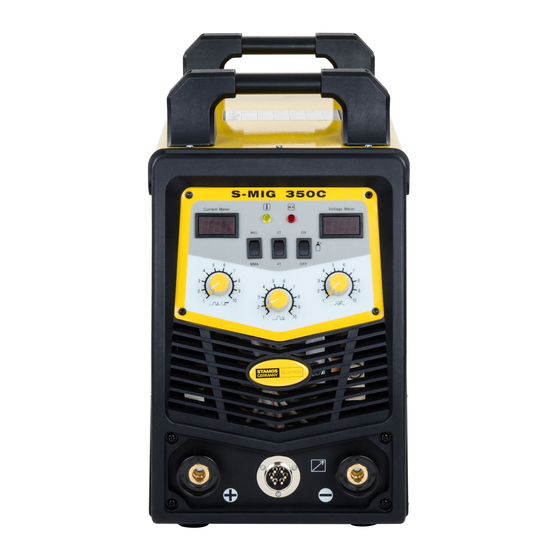
- Página 7 Gelbe LED Überhitzungsanzeige – kein Schweißstrom Rote LED Störungen Voltmeter Anzeige der Schweißspannung S-MIG 350 C INBETRIEBNAHME Anschlüsse Anschluss Bren- Anschluss des MIG/MAG-Brennerkabels nerkabel Drehknopf Einstellen des Schweißstroms Pluspol Stromversorgung für die Drahtvorschu- Schweißstrom beinheit oder das MMA Kabel Taster Drahtvor- Manueller Drahtvorschub zum Einfädeln Anschluss Steue- Anschluss der Steuerungsleitung der...
- Página 8 Bedienpanel Gas - Wippschal- Öffnen und Zuschalten des Magnetventils Gelbe LED Überhitzungsanzeige – kein Schweißstrom Rote LED Störungen Voltmeter Anzeige der Schweißspannung ÜBERBLICK IGbT - Ein Bipolartransistor mit isolierter Gate-Elektro- IGbT de (english Insulated Gate Bipolar Transistor, kurz IGBT) ist ein Halbleiterbauelement, das zunehmend in der Leistungselektronik verwendet wird, da es Vorteile des Bipolartransistors (z.B.
- Página 9 POWER-VENTILATOREN - Die hochqualitativen Vorbereitung der Drahtvorschubeinheit Ventilatoren gewährleisten eine optimale Abkühlung der Hitze die bei der Arbeit mit diesem Schweißgerät ent- Schauen Sie auf die Mobile Drahtvorschubeinheit steht. Bitte beachten Sie die Größe der Spulen-Halterung. Diese muss mit dem Durch- messerder Spule übereinstimmen.
-
Página 10: Notwendiges Zubehör
SCHUTZGAS-SCHWEISSEN / S-MIG 250P / Allgemeines Hauptsächlicher Einsatzbereich in Werkstätten, universell einsetzbar und sowohl für dünnere Bleche als auch für stärkere Materialien geeignet. Es gilt je mehr Schweiß- stufen das Gerät hat, desto besser kann man auch im Blechbereich arbeiten. Notwendiges Zubehör Mischgas Co2/Argon, Schweißdraht, Schweißschild, Druckminderer. - Página 11 Parametertabellen Störung Ursache & Abhilfe Beispiel Nähte oxidiertes • Bei langem Lichtbo- Stumpfstoß (I-Naht) gen in der Vertiefung Aussehen schweißen • Spannung einstellen • Draht verbogen oder zu weit aus der Draht- führung • Falsche Drahtvorschub- geschwindigkeit Blechstärke Abstand g Drahtstärke Schweiß...
- Página 12 Überlappungsstoß Blechstärke Größe der Drahtstärke Schweiß - Schweiß- Schweiß- Gasfluss t (mm) Ecke I (mm) (mm) strom (A) spannung geschw. (L / min) (cm / Min) 2,5 - 3,0 0,8 - 0,9 70 - 80 17 - 18 50 - 60 10 - 15 2,5 - 3,0 70 - 100...
- Página 13 Störung, Ursache Beseitigung Viele Spritzer beim Schweißen? Zu viel Draht Drahtvorschubsteller zurückdrehen Zu viel Schweißspannung Spannungsstufenschalter zurückschal- User Manual Werkstück unsauber Reinigen Vorschubmotor läuft nicht? Netzspannung fehlt Netzanschluss überprüfen MIG MAG MMA Netzspannungsschalter steht auf Null Spannungsstufe einstellen Brennerschalter nicht betätigt Brennerschalter betätigen Sicherung Durch autorisierte Elektrofachkraft...
-
Página 14: General Safety Warnings
Double insulated tools are equipped with a polarized plug (one blade is wi Stamos Germany. Please read these instructions carefully before use to achieve the der than the other). This plug will fit in a polarized outlet only one way. If the best results. -
Página 15: Specific Safety Rules
Do not force the tool. Use the correct tool for your application. The correct Always unplug the tool from its electrical outlet before performing and ins- tool will do the job better and safer at the rate for which it is designed. pection, maintenance, or cleaning procedures. -
Página 16: Disposing Of Packaging
WARNING Never use oil or grease on any inlet connector, outlet connector, or cylinder INHALATION HAZARD: Welding and Plasma Cutting Produce valves. TOXIC FUMES. Use only supplied Torch on this Inverter Air Plasma Cutter. Using compo- nents from other systems may cause personal injury and damage compo- Exposure to welding or cutting exhaust fumes can increase the risk of developing nents within. - Página 17 INSTALLATION 3-phase connection The yellow-green wire is used as a PE protec- Connection diagram tive wire connector. The three phases (black, brown and blue) can be freely connected to L1, L2 and L3 en (please have it done only by a qualified electrician).
- Página 18 User panel Inductance Ad- May change welding stability, depth of fusi- justment on and amount of splashes Inching Wire feed witch Current Adjust- Adjust welding current (MMA) 2T/4T-Rocker Choose between self- and nonself-locking ment Switch function Functions – Ro- Choose between MIG and MMA Current Adjust welding current cker Switch...
- Página 19 yellow LED overheat indicator red LED Abnormal indicator Voltmeter Displays the welding voltage S-MIG 350 C USAGE Connectors Connection Connect MIG torch cable Terminal Current Adjust welding current Adjustment Positive OUT Reliably connects with the cable of the Inching switch Wire feed wire feeder or MMA cable Aviation Socket...
- Página 20 Gas – Rocker Check the solenoid valve User panel Switch Yellow LED Overheat indicator Red LED Abnormal indicator Voltmeter Displays the welding voltage OVERVIEW IGbT - A bipolar transistor with insulated gate elect- IGbT rode (english Insulated Gate Bipolar Transistor, short IGBT) is a semiconductor device that is used increasingly in power electronics, as there advantages of the bipolar transistor (eg, good transmission behavior, high blocking...
- Página 21 SPOT / SLOT WELDING – Choose between spot POWER-VENTILATORS - This kind of high quality or slot welding (only S-MIG 250C) ventilators ensure an optimal cooling that arise by wor- king with this high end apparatus. POWER SWITCH – This welder has a main power switch on the rear panel .
-
Página 22: General Information
GAS-SHIELDED WELDING General information The main area of use is in workshops, universally as well as for thinner metal sheets and thicker materials. The more welding levels the device offers, the more effective it is with sheet metal. Required accessories Mixed-gas CO2/argon, welding wire, welding shield, pressure regulator. - Página 23 Rapid Search Table Disturbance Cause & solution Example Oxidized appearance • Apply a long arc in the I-shaped Butt Welding groove of welds • Adjust voltage • Wire bent or extending too far from the wire guide • Incorrect wire feed speed Plate thick- Gap g(mm)
- Página 24 Lap Welding Plate thick- Welding Solder wire Welding Welding Welding Gas flow (L/ ness t(mm) Angle size l diameter current (A) voltage (V) Speed (cm/ Min) (mm) (mm) Min.) 2,5 - 3,0 0,8 - 0,9 70 - 80 17 - 18 50 - 60 10 - 15 2,5 - 3,0...
-
Página 25: Instrukcja Obsługi
Disturbance, cause Solution Defective power supply element Bring the device to a service workshop Dirty feed spiral Clean and replace Much spatter while welding? Too much wire Reduce the setting of the wire feed Instrukcja obsługi regulator Welding voltage too high Reduce the setting of the voltage regulator Workpiece dirty... -
Página 26: Wskazówki Bezpieczeństwa
• Należy upewnić się, że obszar spawania jest suchy oraz wszystkie przedmioty WSKAZÓWKI BEZPIECZEŃSTWA wraz ze spawarką, które znajdują się na stanowisku spawalniczym. Urządzenie Spawarka ręcznego spawania w osłonie gazów z automatycznym podajnikiem drutu Bezpieczenstwo operatora oraz osób postronnych umożliwia łączenie części metalowych w procesie topienia łączonych krawędzi z zas- Ponieważ... -
Página 27: Ochrona Środowiska
Zakazy zakaz używania otwartego ognia oraz palenia Opis zagrożeń Opis Środki ochronne zakaz naciągania przewodów i węży Przebicie / Skale- Drut może przebić dłonie Należy nosić rękawice zakaz używania urządzenia w warunkach podwyższonej czenie ochronne i trzymać ręce z wilgotności daleka od miejsca, z którego Ostrzeżenie Ostrzeżenie przed niebezpiecznym, wysokim napięciem... -
Página 28: Przed Pierwszym Użyciem
M i n i m a l n y Urządzenie mogą eksploatować osoby, które ukończyły 18 lat. BUDOWA I PODŁĄCZENIE wiek: Wyjątek stanowi osoba nieletnia, która w ramach nauki zawo- du eksploatuje spawarkę pod kontrolą nauczyciela. Schemat podłączenia Szkolenie: Użytkowanie urządzenia wymaga jedynie odpowiedniego zasilanie 3-fazowe 400V regulator przepływu gazu wdrożenia, natomiast nie jest wymagane żadne specjalne sz-... - Página 29 Schemat podłączenia do sieci Żyła żółtozielona służy do podłączenia prze- wodu uziemienia PE. Trzy fazy (żyła czarna, brązowa i niebieska)mogą zostać podłączone dowolnie do L1, L2 oraz L3. Podłączenie może przeprowadzić wyłącznie wykwalifiko- wany elektryk. S-MIG 250 C UCHUCHOMIENIE Podłączenia Przycisk poda- Ręczny posuw drutu wania drutu...
-
Página 30: Panel Sterowania
Panel sterowania żółty wskaźnik Kontrolka przegrzania – brak prądu spa- wania Czerwony Zakłócenia wskaźnik LED Miernik Volt Wskaźnik napięcia spawania S-MIG 350 C URUCHOMIENIE Podłączenia Pokrętło Ustawienie indukcyjności (wpływa na Biegun dodatni Zasilanie prądem podajnika drutu lub kab- indukcyjności stabilność spawania, głębokość topienia) la MMA Pokrętło prąd Ustawienie prądu spawania (MMA) - Página 31 Panel sterowania Pokrętło Ustawienie indukcyjności (wpływa na indukcyjności stabilność spawania, głębokość topienia) Podłączenie Podłączenie kabla / węża z palnikiem MIG/ kabla / węża z Pokrętło Ustawienie napięcia spawania i prędkości palnikiem Pokrętło prąd Ustawienie prądu spawania napięcie spawa- posuwu drutu spawania Pokrętło prąd Ustawienie prądu spawania (także MMA)
- Página 32 Gaz – przełącznik Otwieranie i zamykanie wentyla magnety- - Bardzo wydajne wentylatory WENTYLATORY cznego zapewniają optymalne odprowadzenie ciepła podczas pracy spawarki. żółty wskaźnik Kontrolka przegrzania – brak prądu spawania WŁĄCZNIK SIECIOWY – To urządzenie posiada w tylnej części włącznik główny, który odcina zupełnie Czerwony Zakłócenia urządzenie od sieci zasilającej.
- Página 33 REGULATOR INDUKCYJNOŚCI - Ustawienie indukcyjności (wpływa na stabilność spawania, głębokość topienia). SPAWANIE PUNKTOWE / SPOINOWE – Tu mogą Państwo wybrać pomiędzy spawaniem punktowym a spoinowym (tylko w przypadku S-MIG 250C). Instalacja szpuli drutu oraz nawlekanie drutu Otworzyć lewe drzwiczki boczne spawarki pociągając z dźwignię. Należy zwrócić...
- Página 34 SPAWANIE W OTULINIE GAZÓW OCHRONNYCH Problem Przyczyna / pomoc Przykład Utleniony wygląd spoin • W przypadku długiego Ogólnie łuku elektryczne- Ogólne informacje na temat spawania w osłonie gazów obojętnych. go należy spawać w Ten sposób spawania znajduje zastosowanie w warsztatach, jest uniwersalny i nadaje zagłębieniu się...
- Página 35 Grubość Größe der Drahtstärke Schweiß - Schweiß- Schweiß- Gasfluss Tabela parametrów blachy Ecke I (mm) (mm) strom (A) spannung geschw. (L / min) Złącze grzbietowe (I-spaw) (cm / Min) t (mm) Wielkość 0,8 - 0,9 70 - 80 17 - 18 50 - 60 10 - 15 kąta...
-
Página 36: Rozwiązywanie Problemów
Złącze płaskie Opis problemów Rozwiązanie Duża ilość odprysków podczas spawania? Za dużo drutu Zmniejszyć posuw drutu elektrody Za duże napięcie spawania Zmniejszyć napięcie Brudny przedmiot spawany Wyczyścić Silnik podajnika nie pracuje? Brak zasilania w sieci Sprawdzić podłączenie do sieci elekt- rycznej Grubość... -
Página 37: Consignes De Sécurité Générales
Félicitation pour votre achat du poste à souder MIG/MAG/MMA de chez Stamos Germany Veuillez consulter et lire ce guide attentivement afin d'utiliser ce poste à souder le plus efficacement possible. CONSIGNES DE SÉCURITÉ GÉNÉRALES Appareil Les postes à souder manuels avec gaz de protection et déroulement automatique du fil permettent de relier diverses parties métalliques en les fusionnant grâce à... -
Página 38: Protection De L'environnement
UTILISATEUR ET ENTOURAGE Interdictions Incendie Étant donné que le processus de soudage provoque d’intense rayons lumineux et thermiques, il est obligatoire d’avoir pris des dispositions de sécurité et de protec- Feu ouvert tion tant pour l’utilisateur que pour les autres personnes présentes. Fumer Avertissements Tensions électriques dangereuses... -
Página 39: Avant La Première Utilisation
QUALIFICATION: Hormis des indications détaillées d’une personne compétente Danger Description Mesure préventive en la matière, l'utilisation de l'appareil ne nécessite aucune qualification particulière. Perforation / Il est possible de se Porter des gants de Piqûre AGE MINI- L'appareil peut être utilisé exclusivement par des personnes perforer la main à... -
Página 40: Montage Et Raccordement
MONTAGE ET RACCORDEMENT Plan de raccordement au secteur Le fil jaune-vert est destiné à la prise du con- Montage et branchements ducteur de protection (PE). Les trois phases (noir, marron et bleu) peuvent être connecté- es au choix à L1, L2 et L3. Les travaux sur le Régulateur de gaz Distributeur d’alimentation système électrique doivent uniquement être... -
Página 41: Bouton Rotatif
Panneau de commande Bouton rotatif pour Ajuster l'inductance (influence la l'inductance stabilité de soudage, la profondeur de sou- Touche pour dérouler le Dévider manuellement la bobine de fil dage et la quantité de projection) Bouton rotatif Ajuster le courant de soudage (MMA) Commutateur 2T/4T Actionne le mode blocage / pas de blocage du courant de soudage... - Página 42 LED jaune Indicateur de surchauffe / absence de cou- rant de soudage LED rouge Panne / Problème de fonctionnement Voltmètre Affichage de la tension de soudage S-MIG 350 C EN SERVICE Raccordements Raccordement de la tor- Raccordement du câble de la torche MIG/ Bouton rotatif Ajuster le courant de soudage Pôle positif...
- Página 43 Panneau de commande Interrupteur d'ouverture Ouverture et fermeture de l'électrovanne de l'arrivée du gaz LED jaune Indicateur de surchauffe / absence de courant de soudage LED rouge Panne / Problème de fonctionnement Voltmètre Affichage de la tension de soudage APERÇU IGbT = un transistor bipolaire à...
- Página 44 POWER-VENTILATEURS = Les ventilateurs ult- Préparation de l'unité de déroulement du fil ra-performants garantissent un refroidissement optimal de l'appareil pendant son utilisation. Regardez le système de déroulement du fil mobile Respectez la dimension du support de la bobine. Celui-ci doit correspondre au diamètre de la bobine.
-
Página 45: Soudage Avec Gaz De Protection / S-Mig 250P
SOUDAGE AVEC GAZ DE PROTECTION / S-MIG 250P / Informations générales Installation idéale en ateliers, application universelle, approprié aussi bien pour les tôles fines que pour les matériaux plus épais. Plus l'appareil possède des niveaux d'intensité de soudage différents, plus facile sera le travail de la tôle. Équipement nécessaire Gaz mixte CO2/Argon, fil de soudage, masque de soudage, réducteur de pression également adapté... -
Página 46: Tableaux De Paramètres
Tableaux de paramètres Problème Cause et solution Exemple Soudures oxydées • Si l'arc est trop long, Aboutage (Soudure) soudez plus en profon- apparentes deur • Ajustez la tension • Fil courbé ou trop éloigné dans le disposi- tif 'acheminement • Vitesse d'acheminement du fil non-adaptée Épaisseur... - Página 47 Recouvrement Épaisseur Distance Épaisseur Courant de Tension de Vitesse de Débit de de la tôle t g´(mm) du fil (mm) soudage (A) soudage (V) soudage gaz (L / min) (mm) (cm / Min) 2,5 - 3,0 0,8 - 0,9 70 - 80 17 - 18 50 - 60 10 - 15...
-
Página 48: Instruzioni Per L´uso
Problème, cause Solution Beaucoup de projections lors du soudage? Excès de fil Réduisez l'acheminement du fil Courant de soudage excessif Réduisez le courant avec le commuta- teur INSTRUZIONI PER L´USO Pièce d'ouvrage sale Nettoyez la pièce d'ouvrage Le moteur du dispositif d'acheminement du fil ne fonctionne pas? Pas de tension Réexaminez le raccordement au secteur... -
Página 49: Installazione Del Dispositivo
Grazie di aver acquistato questa saldatrice MIG/MAG/MMA di Stamos Germany Si UTENTE E ULTERIORI PERSONE prega di leggere attentamente queste istruzioni d'uso per ottenere sempre i migliori Scintille o calore eccessivo possono insorgere durante il processo di saldatura. Si risultati. -
Página 50: Protezione Dell'ambiente
DIVIETI Fuoco Rischi Descrizione Misure di prevenzione Traforo Puntura Le mani possono essere guanti protettivi, tenere le Luce perforate dal filo mani lontane dall'uscita del Fumo filo ATTENZIONE Tensione elettrica pericolosa Spruzzo di scorie Perle di saldatura possono Indossare abbigliamento Pericolo di inciampare schizzare e provocare ustio- protettivo e una maschera... -
Página 51: Trasporto E Stoccaggio
ETÀ MINIMA: L'apparecchio può essere usato solo da persone che abbi- STRUTTURA E COLLEGAMENTO ano compiuto il 18esimo anno d'età. Viene fatta eccezio- ne nel caso di utilizzo da parte di un giovane nell'ambito di Schema di collegamento e della struttura formazione professionale sotto la sorveglianza di persona- le specializzato. -
Página 52: Prima Accensione
Piano di collegamento Il contrassegno giallo-verde indica il collega- mento del conduttore di protezione PE. Le tre fasi (nero, marrone ed azzurro) possono essere fissate facoltativamente a L1, a L2 e a L3. Si prega di lasciar effettuare questi colle- gamenti da personale esperto. - Página 53 Pannello operatore Spia LED gialla Indicatore di surriscaldamento - nessuna corrente di saldatura Spia LED rossa Indica eventuali guasti Voltametro Indicatore della tensione di saldatura S-MIG 350 C PRIMA ACCENSIONE Collegamenti Manopola della Impostazione dell'induttività (influenza Polo positivo Alimentazione elettrica per l'unità spola induttività...
-
Página 54: Pannello Operatore
Pannello operatore Manopola Impostazione dell'induttività (influenza induttività la stabilità di saldatura, profondità di fusio- Collegamento del Collegamento per il cavo della torcia MIG/ ne e quantità degli schizzi) cavo della torcia Manopola Impostazione della tensione di saldatura e Manopola Regolazione della corrente di saldatura della tensione Velocità... -
Página 55: Visione D'insieme
Interruttore a Accendere e spegnere l'elettrovalvola VENTOLE POWER - Le ventole di alta qualità ga- bascula per il gas rantiscono un raffreddamento ottimale per disperdere il calore generato dall'utilizzo del dispositivo. Spia LED gialla Indicatore di surriscaldamento - nessuna corrente di saldatura INTERRUTTORE ALIMENTAZIO- –... - Página 56 Preparazione dell'unità spola avvolgi filo Guardare l'unità avvolgi filo mobile Prestare attenzione alla dimensione del sostegno della bobina Le grandezze de- vono corrispondere al diametro della bobina. Posizionare quindi la bobina sulla barra dentata. Svolgere il filo in senso orario. L'inizio del fino è solitamente assicurato alla bo- bina in modo che il filo non si possa staccare dalla bobina.
-
Página 57: Accessori Necessari
SALDATURA CON GAS DI PROTEZIONE /S-MIG 250P/ Problema Causa e rimedio Esempio Giunture apparente- • Saldare in profondità ISTRUZIONI GENERALI in caso di arco di luce Campo d’impiego principale in officine, impiegabile universalmente e anche per la- mente ossidate lungo miere più... - Página 58 Tabelle dei parametri Resisten- Dimensioni Resistenza Corrente Tensione di Velocità di Flusso di za della dell'angolo I del filo di saldatura saldatura saldatura gas (L/ min) Giunto saldato (giunto di testa) lamiera t (mm) (mm) (cm/ min) (mm) 2,5 - 3,0 0,8 - 0,9 70 - 80 17 - 18...
-
Página 59: Analisi Guasti
Giunto a sovrapposizione Problema, causa Soluzione Molti schizzi durante la saldatura? Troppo filo Riavvolgere la bobina dell'avvolgi filo Tensione di saldatura eccessiva Reinnestare l'interruttore dei livelli di tensione Pezzo da lavorare sporco Pulirlo Resistenza Punto di Resistenza Corrente Tensione di Tensione di Flusso di della amiera... -
Página 60: Consejos Generales De Seguridad
Felicidades por la compra de un equipo de soldadura MIG/MAG/MMA de Stamos Germany. Por favor, lea las instrucciones con atención para obtener en todo momento los mejores resultados con este equipo de soldadura. CONSEJOS GENERALES DE SEGURIDAD El equipo Los equipos de soldadura bajo gas protector con alimentación automática del hilo MANUAL DE INSTRUCCIONES permiten soldar piezas metálicas. -
Página 61: Protección Del Medio Ambiente
EL USUARIO Y OTRAS PERSONAS Prohibiciones Fuego abierto Durante los trabajos de soldadura se desprende radiación y calor. Por esta razón le recomendamos utilizar medios de protección adecuados para el usuario y terceras Luz abierta personas. Humo Peligros Tensión eléctrica Peligro de tropiezo Evite que el usuario y terceras personas se expongan a los efectos del arco voltaico y del metal candente. -
Página 62: Requisitos Al Usuario
EDAD Este equipo solo puede ser utilizado por mayores de 18 años. Riesgos Descripción Medida preventiva MÍNIMA: Los menores de edad podrán utilizar el equipo únicamente Pinchazo El hilo metálico puede Utilice siempre guantes de para fines formativos y siempre bajo supervisión de un pinchar las manos protección y mantenga las formador. -
Página 63: Montaje Y Conexión
MONTAJE Y CONEXIÓN Indicaciones para conexión a la corriente: Diagrama de montaje y conexión El cable amarillo/verde está previsto para la conexión a tierra PE. Las tres fases se pueden conectar a cualquiera de las tomas L1, L2 o L3. Por favor, deje que esta tarea la realice un regulador del flujo de enchufe trifásico electricista cualificado. - Página 64 Panel de funcionamiento Regulador de la Regula la inductancia (Influencia en la inductancia estabilidad de la soldadura, profundidad y Botón de alimentación Alimentación manual para enhebrar el hilo salpicadura de la soldadura). del hilo Regulador del amperaje Ajuste de la corriente de soldadura Interruptor - 2T/4T Cambio entre función de bloqueo - función de no bloqueo.
- Página 65 LED amarillo Indicador de sobrecalentamiento - ninguna corriente de soldadura LED rojo Avería Voltímetro Indica la tensión de soldadura S-MIG 350 C PUESTA EN FUNCIONAMIENTO Conexiones Conexión de la antorcha Conexión del cable MIG/MAG con manguera Regulador del amperaje Ajuste de la corriente de soldadura Regulador de la Regula la inductancia (Influencia en la inductancia...
-
Página 66: Descripción
Panel de funcionamiento Interruptor de Abre y cierra la válvula LED amarillo Indicador de sobrecalentamiento - ninguna corriente de soldadura LED rojo Avería Voltímetro Indica la tensión de soldadura DESCRIPCIÓN IGbT - El transistor bipolar con electrodo de puerta IGbT aislado (IGBT) es un componente semiconductor, que se utiliza cada vez más en la electrónica avanzada, ya que combina las ventajas del transistor bipolar (e.g. -
Página 67: Ventiladores
- Los ventiladores de gran Preparación de la unidad de alimentación del hilo VENTILADORES potencia garantizan una refrigeración óptima para el calor que genera este dispositivo de alta gama. Mire la unidad móvil de alimentación del hilo Tenga en cuenta el tamaño del soporte de la bobina, ya que tiene que coincidir con su diámetro. -
Página 68: Accesorios Necesarios
SOLDADURA AL ARCO CON GAS PROTECTOR /S-MIG 250P INFORMACIÓN GENERAL Se utiliza en todo tipo de talleres para la soldadura de materiales tanto finos como gruesos. Cuantos más niveles de soldadura tenga el equipo, mejor podrá soldar chapas metálicas finas. Accesorios necesarios Mezcla de gases Co2/Argón, hilo, careta de soldadura y regulador de presión. -
Página 69: Tablas De Parámetros
Tablas de parámetros Problema Causa y solución Ejemplo El cordón está oxidado • Cuando suelda en A tope (tipo I) profundidad con un arco largo • Ajuste el voltaje • Hilo doblado o muy lejos de la alimentación • Velocidad de alimentación del hilo incorrecta Grosor del... -
Página 70: Detección De Fallos
Unión tipo traslape Grosor del Distancia Diámetro Amperaje Voltaje(V) Velocidad Flujo del gas metal (mm) "I"´(mm) del hilo de soldadu- (l./min.) (mm) ra (cm/ min) 2,5 - 3,0 0,8 - 0,9 70 - 80 17 - 18 50 - 60 10 - 15 2,5 - 3,0 70 - 100... - Página 71 Problema, causa Solución ¿Se crea mucha salpicadura al soldar? Demasiado hilo Reduzca el avance del hilo Voltaje de soldadura muy elevado Reduzca el voltaje de soldadura desde el regulador de tensión Pieza de trabajo sucia Límpiela ¿El motor de alimentación no funciona? Corriente insuficiente Compruebe la conexión a la red eléctrica...
- Página 72 Hiermit bestätigen wir, dass die hier in dieser Anleitung aufgeführten Geräte CE-konform sind. We hereby certify that the appliances listed in this manual are CE compliant. Par la présente, nous confirmons que les appareils présentés dans ce mode d´emploi sont conformes aux normes Ce. Niniejszym potwierdzamy, że urządzenia opisane w tej instrukcji są...
- Página 73 Umwelt- und Entsorgungshinweise Hersteller an Verbraucher Sehr geehrte Damen und Herren, gebrauchte Elektro- und Elektronikgeräte dürfen gemäß europäischer Vorgaben [1] nicht zum unsortierten Siedlungsabfall gegeben werden, sondern müssen getrennt erfasst werden. Das Symbol der Abfalltonne auf Rädern weist auf die Notwendigkeit der getrennten Sammlung hin.