Tabla de contenido
Publicidad
Idiomas disponibles
Idiomas disponibles
Enlaces rápidos
ATTACH YOUR RECEIPT HERE
Serial Number ____________________ Purchase Date _____________________
Questions?
Call customer service at 1-877-4GATEHS, 8:00 a.m. - 8:00 p.m., EST, Monday - Friday.
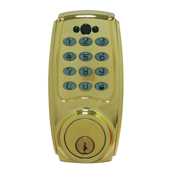
ELECTRONIC KEYPAD DEADBOLT
1
2
3
4
5
6
7
8
9
C
0
ITEM #0399129/0399128
MODEL #G27D01/G2X2D01
Español p. 37
Español p.
XX
Publicidad
Capítulos
Tabla de contenido
Solución de problemas

Manuales relacionados para Gate House G27D01

Resumen de contenidos para Gate House G27D01
- Página 1 ITEM #0399129/0399128 ELECTRONIC KEYPAD DEADBOLT MODEL #G27D01/G2X2D01 Español p. 37 Español p. ATTACH YOUR RECEIPT HERE Serial Number ____________________ Purchase Date _____________________ Questions? Call customer service at 1-877-4GATEHS, 8:00 a.m. - 8:00 p.m., EST, Monday - Friday.
-
Página 2: Tabla De Contenido
TABLE OF CONTENTS SAFETY INFORMATION..................PACKAGE CONTENTS..................PREPARATION....................... 03-08 INSTALLATION....................... 09-17 OVERVIEW OF FUNCTIONS.................. CODES INFORMATION..................SETTING MODE 1. AUTOMATIC - BOLT DIRECTION DETERMINATION........2. CHANGE PRESET OR CURRENT PROGRAMMING CODE......3. ADD NEW USER CODE..................4. DELETE INDIVIDUAL EXISTING USER CODE..........5. -
Página 3: Safety Information
SAFETY INFORMATION 1. Do not attempt to disassemble any internal components of this lockset as this WILL void the limited warranty. 2. Do not drop or hit/strike the lockset as excessive shock may result in permanent damage. 3. Do not use sharp objects to press key buttons. 4. -
Página 4: Package Contents
PACKAGE CONTENTS PART DESCRIPTION QUANTITY PART DESCRIPTION QUANTITY Exterior Assembly Interior Cover Power Strip Latch Tailpiece 3/4 in. (19 mm) Wood Screw Mounting Plate Strike Plate 2-1/8 in. (54 mm) Mounting Bolt 3 in. (76 mm) Wood Screw Interior Assembly Reinforced Strike Plate 13/16 in. -
Página 5: Preparation
PREPARATION Before beginning installation of product, make sure all parts are present. Compare parts with package contents list and hardware contents list. If any part is missing or damaged, do not attempt to assemble, install or operate the product. ESTIMATED ASSEMBLY TIME: 40 - 60 MINUTES TOOLS NEEDED FOR NEW INSTALLATION (NOT INCLUDED): •... - Página 6 PREPARATION 1. MARK DOOR WITH TEMPLATE (REFER TO PAGE 36, 37) a. Use TEMPLATE to mark centerline on door for keypad deadbolt about 3 in. (76 mm) to 6 in. (152 mm) above the existing knob or lever. b. Face door swings to align and fold template as shown. Template Centerline Mark door edge approximately...
- Página 7 PREPARATION 2. MARK AND DRILL PILOT HOLES Select backset: 2-3/8 in. (60 mm) or 2-3/4 in. (70 mm). Refer to page 09 for latch backset adjustment if needed. Mark and drill 1/8 in. (3 mm) pilot holes as shown. Centerline 2-1/8 in.
- Página 8 PREPARATION 3-1. DRILL HOLES a. Drill a 2-1/8 in. (54 mm) hole on the door face from both sides to avoid wood splitting. b. Use a 2 in. (51 mm) 6d common nail and press it from inside the 2-1/8 in. (54 mm) hole through the pilot hole to mark centerlines on jamb exactly opposite center of deadbolt latch hole.
- Página 9 PREPARATION 3-2. DRILL HOLES c. Drill a 1 in. (25 mm) hole in the door edge for the latch. d. Use faceplate of the latch (J) as a pattern for mortise and pilot holes. Chisel 1/8 in. (3 mm) deep. Faceplate should fit flush. 1 in.
- Página 10 PREPARATION 4. PREPARE DOOR JAMB AND INSTALL STRIKE PLATE Mark outline for dust box (O) and then drill a hole 1-3/16 in. (30 mm) deep by 1-9/16 in (40 mm) tall by 1 in. (25 mm) wide to allow for installation of dust box (O). Chisel a 5/32 in. (4 mm) deep outline for the strike plate (L) on the door jamb.
-
Página 11: Installation
INSTALLATION 1. LATCH BACKSET ADJUSTMENT Latch backset adjustment applies only when your door needs a 2-3/4 in. (70 mm) backset. Please follow below diagrams. Skip this if your door is for a 2-3/8 in. (60 mm) backset. For 2-3/4 in. Twist 1/8 turn and pull. - Página 12 INSTALLATION 2. INSTALL LATCH IN MORTISED AREA If the backset of your door is 2-3/8 in. (60 mm), install latch (J) with the 3/4 in. (19 mm) wood screws (K). Backset...
- Página 13 INSTALLATION Thread the power strip (B) on the exterior assembly (A) through the hole in the door and under the latch (J). The latch bolt should be retracted.
- Página 14 INSTALLATION The bulged part of mounting plate (B) must face toward the door. Slide the power strip (B) through the notch of the mounting plate (D).
- Página 15 INSTALLATION Keep the mounting plate (D) parallel to the door edge. Attach mounting plate (D) to door using 2-1/8 in. (54 mm) mounting bolt (E). Tighten.
- Página 16 INSTALLATION Firmly connect the power strip (B) to the connector port on the interior assembly (F). NOTE: Insert the red pins into the red sockets and make sure the colored part matches.
- Página 17 INSTALLATION The power strip (B) must be arranged as shown.
- Página 18 INSTALLATION Attach the interior assembly (F) using two 5/16 in. (8 mm) screws (H) – one on each side – and one 13/16 in. (20.5 mm) screw (G) on the bottom. Tighten. AUTO LOCK Install 4 AA Alkaline batteries (not included). NOTE: It is strongly recommended that you use only ALKALINE BATTERIES to operate this product.
- Página 19 INSTALLATION Remove the interior cover (I) to replace the Installation batteries or set codes. Place the interior cover (I) is complete. on the interior assembly (F).
-
Página 20: Overview Of Functions
OVERVIEW OF FUNCTIONS EXTERIOR INDICATED LIGHT 1. Green light: Indicates the user code entered is a valid code. 2. Red light: The user code entered is an invalid code or the Exterior unit is in programming mode. indicated light 3. Yellow light: Low battery warning. NOTE: All batteries should be replaced for home security. -
Página 21: Codes Information
CODES INFORMATION PROGRAMMING CODE (MASTER CODE) 1. Only one programming code will be allowed and the lockset can be programmed/activated by programming code. 2. A programming code is restricted to 6 digits. The preset programming code is 123456 (factory setting). 3. -
Página 22: Setting Mode
SETTING MODE AUTOMATIC - BOLT DIRECTION DETERMINATION 1. Install four ALKALINE Batteries. 2. Press [SET] button for more than 2 seconds. The red LED will light and the lockset will beep twice. You are now in programming mode. 3. Enter 123456 (or current programming code) and then press button. -
Página 23: Change Preset Or Current Programming Code
SETTING MODE CHANGE PRESET OR CURRENT PROGRAMMING CODE IMPORTANT: The preset programming code is 123456. Please change the programming code before operating the lockset. 1. Press [SET] button for more than 2 seconds. The red LED will light and the lockset will beep twice. You are now in programming mode. -
Página 24: Add New User Code
SETTING MODE ADD NEW USER CODE 1. Press [SET] button for more than 2 seconds. The red LED will light and the lockset will beep twice. You are now in programming mode. 2. Enter 123456 (or current programming code) and then press button. -
Página 25: Delete Individual Existing User Code
SETTING MODE DELETE INDIVIDUAL EXISTING USER CODE 1. Press [SET] button for more than 2 seconds. The red LED will light and the lockset will beep twice. You are now in programming mode. 2. Enter 123456 (or current programming code) and then press button. -
Página 26: Setting Mode
SETTING MODE DELETE ALL EXISTING USER CODES AT ONCE 1. Press [SET] button for more than 2 seconds. The red LED will light and the lockset will beep twice. You are now in programming mode. 2. Enter 123456 (or current programming code) and then press button. -
Página 27: Restore Factory Setting
SETTING MODE RESTORE FACTORY SETTING 1. Remove one battery from the battery pack. 2. Simultaneously press the [SET] button and replace the battery. The green LED will light and then the lockset will beep twice. All functions will be restored back to factory setting. -
Página 28: Auto Locking Function
SETTING MODE AUTO LOCKING FUNCTION Switch to [ON] position to activate auto locking function. Switch back to [OFF] position to cancel auto locking function. AUTO LOCK AUTO LOCK NOTE: 1. The latch bolt will be automatically latched after 10 seconds. Please make sure the door is properly closed while the auto locking function is on. -
Página 29: Operation Mode
OPERATION MODE LOCK OPERATION To lock: From outside: Press button to lock the door. The green LED will be on and the lockset will beep. From inside: Turn interior thumbturn to horizontal position to lock. To unlock: From outside: Enter a valid user code (4 to 6 digits) to retract the latch bolt. From inside: Turn interior thumbturn to vertical position to unlock. -
Página 30: Security Mode
OPERATION MODE SECURITY MODE 1. Alarm sounds for 10 seconds and unit deactives for 1 minute after 4 consecutive incorrect code access attempts. 2. Back-up key override: The deadbolt can be fully operated (locked or unlocked) by a valid conventional key from outside. -
Página 31: Troubleshooting
TROUBLESHOOTING PROBLEM CORRECTIVE ACTIONS 1. Check center of strike hole for alignment with The lockset does not latch hole on the door to ensure free movement operate correctly after of the latch bolt. installation. 2. Refer to page 19 [AUTOMATIC-BOLT DIRECTION DETERMINATION section]. - Página 32 TROUBLESHOOTING PROBLEM CORRECTIVE ACTIONS Yellow LED light keeps The battery is getting low. Replace ALL batteries flashing. for best performance. Only use alkaline batteries. 1. Check battery installation. 2. The battery is low if the yellow LED light keeps Keypad does not respond. flashing.
- Página 33 TROUBLESHOOTING PROBLEM CORRECTIVE ACTIONS 1. Make sure the whole code entering process is completed within 10 seconds. Cannot delete all user 2. Make sure the programming code has been codes. entered correctly. button should be pressed for more than 3 seconds. 1.
- Página 34 TROUBLESHOOTING PROBLEM CORRECTIVE ACTIONS 1. Make sure the programming code or user code has been entered correctly. Lockset is not able to 2. The battery is low if the yellow LED light keeps flashing. Please replace all batteries. unlock by keypad. 3.
-
Página 35: Information
INFORMATION SECURITY INSTRUCTION: 1. Do not disclose your programming code to anyone else. 2. Keep a written copy of user codes that you have programmed into the lock and place it in a safe place. You may use the table below to record your information. 3. -
Página 36: Warranty
WARRANTY The retailer of this product hereby warrants, subject to the conditions set forth below, that it will either repair or replace, at its option, this product if it proves to be defective by reason of improper workmanship or materials within the original purchaser's limited time. In order to obtain repairs or replacement under this limited warranty you must bring this product to the retailer's store in which you bought it. -
Página 37: Federal Communications Commission Statement
FEDERAL COMMUNICATIONS COMMISSION STATEMENT This device complies with Part 15 of the FCC. Operation is subject to the following two conditions: (1) this device may not cause harmful interference, and (2) this device must accept any interference received, including interference that may cause undesired operation. Changes or modifications not expressly approved by the party responsible for compliance could void the user‘s authority to operate the equipment. -
Página 38: Template
TEMPLATE TOOLS NEEDED Fold here Place on door edge FOR NEW INSTALLATION: Drill 1 in. (25 mm) hole at center of door edge. 2 in. 1-3/4 in. ø 2-1/8 in. (54 mm) Backset 2-3/8 in. (60 mm) 1-9/16 in. 1-3/8 in. Backset 2-3/4 in. -
Página 39: Cerradura Electrónica Con Pestillo Desde El Teclado
ARTÍCULO #0399129/0399128 CERRADURA ELECTRÓNICA CON PESTILLO DESDE EL TECLADO MODELO #G27D01/G2X2D01 ADJUNTE SU RECIBO AQUÍ Número de serie ___________________ Fecha de compra ___________________ ¿Preguntas? Llame a Servicio al Cliente al 1-877-4GATEHS, de lunes a viernes de 8 a.m. a 8:00 p.m. - Página 40 ÍNDICE INFORMACIÓN DE SEGURIDAD................CONTENIDO DEL PAQUETE ................PREPARACIÓN....................... 39-44 INSTALACIÓN......................45-53 DESCRIPCIÓN GENERAL DE LAS FUNCIONES..........INFORMACIÓN DE CÓDIGOS................MODO DE CONFIGURACIÓN 1. DETERMINACIÓN AUTOMÁTICA DE LA DIRECCIÓN DEL PERNO....2. CAMBIO DEL CÓDIGO DE PROGRAMACIÓN PREESTABLECIDOS O ACTUALES.. 3.
-
Página 41: Información De Seguridad
INFORMACIÓN DE SEGURIDAD 1. No intente desensamblar ningún componente interno de esta cerradura, ya que esto ANULARÁ la garantía limitada. 2. No deje caer ni golpee la cerradura, ya que sacudirla excesivamente podría provocar daños permanentes. 3. No use objetos afilados para presionar los botones. 4. -
Página 42: Contenido Del Paquete
CONTENIDO DEL PAQUETE PIEZA DESCRIPCIÓN CANTIDAD PIEZA DESCRIPCIÓN CANTIDAD Ensamble exterior Cubierta interior Enchufe múltiple Pestillo Tubo de descarga Tornillo para madera de 3/4 pulg (1,91 cm) Placa de montaje Placa del cerrojo Perno de montaje de 2-1/8 pulg (5,40 cm) Tornillo para madera de 3 pulg (7,62 cm) Ensamble interior Placa del cerrojo reforzada... -
Página 43: Preparación
PREPARACIÓN Antes de comenzar a instalar el producto, asegúrese de tener todas las piezas. Compare las piezas con la lista del contenido del paquete y la lista de aditamentos. No intente ensamblar, instalar ni usar el producto si falta alguna pieza o si estas están dañadas. - Página 44 PREPARACIÓN 1. MARQUE LA PUERTA CON LA PLANTILLA (CONSULTE LAS PÁGINAS 36 Y 37) a. Use la PLANTILLA para marcar la línea central en la puerta, para la cerradura con pestillo desde el teclado, aproximadamente a 7,62 cm (3 pulg) a 15,24 cm (6 pulg) por sobre la perilla o palanca existente.
- Página 45 PREPARACIÓN 2. MARQUE Y TALADRE ORIFICIOS GUÍA Seleccione el seguro: 6,03 cm (2-3/8 pulg) o 6,99 cm (2-3/4 pulg). Consulte la página 09 para conocer el ajuste del seguro del pestillo, de ser necesario. Marque y taladre orificios guía de 3,18 mm (1/8 pulg), como se muestra. Centerline 2-1/8 in.
- Página 46 PREPARACIÓN 3-1. TALADRE LOS ORIFICIOS a. Taladre un orificio de 5,40 cm (2-1/8”) en la superficie de la puerta, desde ambos lados para evitar astillar la madera. b. Use un clavo común de 2 pulg (5,08 cm) 6d y presiónelo desde el interior del orificio de 5,40 cm (2-1/8 pulg), a través del orificio guía, para marcar las líneas centrales en los marcos interiores para puertas, en los centros exactamente opuestos del orificio del pestillo de la cerradura.
- Página 47 PREPARACIÓN 3-2. TALADRE LOS ORIFICIOS c. Taladre un orificio de 2,54 cm (1 pulg) en el borde de la puerta para el pestillo. d. Use la placa frontal del pestillo (J) como diseño para la muesca y los orificios guía. Cincel de 3,18 mm (1/8 pulg) de profundidad.
- Página 48 PREPARACIÓN 4. PREPARE LA JAMBA DE LA PUERTA E INSTALE LA PLACA DEL CERROJO Marque el contorno para el colector de polvo (O) y luego taladre un orificio de 3,02 cm (1-3/16 pulg) de profundidad, 3,97 cm (1-9/16 pulg) de alto y 2,54 cm (1 pulg) de ancho para permitir la instalación del colector de polvo (O).
-
Página 49: Instalación
INSTALACIÓN 1. AJUSTE DEL SEGURO DEL PESTILLO El ajuste del pestillo solo se aplica cuando la puerta necesita un seguro de 6,99 cm (2-3/4 pulg). Siga los diagramas que aparecen a continuación. Omita esto si su puerta es para un seguro de 6,03 cm (2-3/8 pulg). Gire 1/8 de vuelta y jale. - Página 50 INSTALACIÓN 2. INSTALE EL PESTILLO EN EL ÁREA RANURADA Si el seguro de la puerta es de 6,03 cm (2-3/8 pulg), instale el pestillo (J) con los tornillos para madera de 3/4 pulg (1,91 cm). Seguro...
- Página 51 INSTALACIÓN Enrosque el enchufe múltiple (B) en el ensamble exterior (A) a través del orificio de la puerta y debajo del pestillo (J). El perno del pestillo debe estar retraído.
- Página 52 INSTALACIÓN La parte abultada de la placa de montaje (B) debe mirar hacia la puerta. Deslice el enchufe múltiple (B) a través de la ranura de la placa de montaje (D).
- Página 53 INSTALACIÓN Mantenga la placa de montaje (D) paralela al borde de la puerta. Fije la placa de montaje (D) a la puerta con el perno de montaje de 2-1/8 pulg (5,40 cm) (E). Apriete.
-
Página 54: Cómo Eliminar Todos Los Códigos De Usuario Individuales Existentes De Una Vez
INSTALACIÓN Conecte firmemente el enchufe múltiple (B) con el puerto del conector en el ensamble interior (F). NOTA: Inserte las clavijas rojas en los sockets rojos y asegúrese de que la parte coloreada combine. - Página 55 INSTALACIÓN El enchufe múltiple (B) debe estar en ladisposición que se muestra.
- Página 56 INSTALACIÓN Fije el ensamble interior (F) con dos tornillos de 5/16 pulg (7,94 mm) (H), uno a cada lado, y un tornillo de 13/16 pulg (2,06 mm) (G) en la parte inferior. Apriete. AUTO LOCK Instale 4 baterías alcalinas AA (no se incluyen). NOTA: Se recomienda encarecidamente que use solo BATERÍAS ALCALINAS para operar este producto.
- Página 57 INSTALACIÓN Coloque la cubierta interior (I) para reemplazar las baterías La instalación o configurar los códigos. está terminada. Coloque la cubierta interior (I) en el ensamble interior (F).
-
Página 58: Descripción General De Las Funciones
DESCRIPCIÓN GENERAL DE LAS FUNCIONES LUZ INDICADORA EXTERIOR 1. Luz verde: Indica si el código de usuario ingresado es un código válido. 2. Luz roja: El código de usuario ingresado no es un código Luz indicadora válido o la unidad está en modo de programación. exterior 3. -
Página 59: Información De Códigos
INFORMACIÓN DE CÓDIGOS CÓDIGO DE PROGRAMACIÓN (CÓDIGO MAESTRO) 1. Solo se permitirá un código de programación y la cerradura se puede programar/activar con el código de programación. 2. El código de programación está restringido a 6 dígitos. El código de programación preestablecido es 123456 (ajuste de fábrica). 3. -
Página 60: Modo De Configuración
MODO DE CONFIGURACIÓN DETERMINACIÓN AUTOMÁTICA DE LA DIRECCIÓN DEL PERNO 1. Instale cuatro baterías ALCALINAS. 2. Presione el botón [SET] (fijar) por más de 2 segundos. El LED rojo se iluminará y la cerradura emitirá un pitido dos veces. Ahora está en modo de programación. 3. -
Página 61: Cambio Del Código De Programación Preestablecidos O Actuales
MODO DE CONFIGURACIÓN CAMBIO DEL CÓDIGO DE PROGRAMACIÓN PREESTABLECIDOS O ACTUALES IMPORTANTE: El código de programación preestablecido es 123456. Cambie el código de programación antes de usar la cerradura. 1. Presione el botón [SET] (fijar) por más de 2 segundos. El LED rojo se iluminará... -
Página 62: Cómo Agregar Nuevo Código De Usuario
MODO DE CONFIGURACIÓN CÓMO AGREGAR NUEVO CÓDIGO DE USUARIO 1. Presione el botón [SET] por más de 2 segundos. El LED rojo se iluminará y la cerradura emitirá un pitido dos veces. Ahora está en modo de programación. 2. Ingrese 123456 (o el código de programación actual) y luego presione el botón Ingrese [20] y luego presione el botón . -
Página 63: Cómo Eliminar Códigos De Usuario Individuales Existentes
MODO DE CONFIGURACIÓN CÓMO ELIMINAR CÓDIGOS DE USUARIO INDIVIDUALES EXISTENTES 1. Presione el botón [SET] por más de 2 segundos. El LED rojo se iluminará y la cerradura emitirá un pitido dos veces. Ahora está en modo de programación. 2. Ingrese 123456 (o el código de programación actual) y luego presione el botón Ingrese [30] y luego presione el botón . - Página 64 MODO DE CONFIGURACIÓN CÓMO ELIMINAR TODOS LOS CÓDIGOS DE USUARIO INDIVIDUALES EXISTENTES DE UNA VEZ 1. Presione el botón [SET] por más de 2 segundos. El LED rojo se iluminará y la cerradura emitirá un pitido dos veces. Ahora está en modo de programación. 2.
-
Página 65: Cómo Restaurar La Configuración De Fábrica
MODO DE CONFIGURACIÓN CÓMO RESTAURAR LA CONFIGURACIÓN DE FÁBRICA 1. Retire una batería del paquete de baterías. 2. Simultáneamente presione el botón [SET] y vuelva a colocar la batería. El LED verde se iluminará y luego la cerradura emitirá un pitido dos veces. Todas las funciones se restaurarán al ajuste de fábrica. -
Página 66: Función De Bloqueo Automático
MODO DE CONFIGURACIÓN FUNCIÓN DE BLOQUEO AUTOMÁTICO Cambie a la posición [ON] (activado) para activar la función de bloqueo automático. Vuelva a la posición [OFF] (desactivado) para cancelar la función de bloqueo automático. AUTO LOCK AUTO LOCK NOTA: 1. El perno del pestillo se cerrará automáticamente en 10 segundos. Asegúrese de que la puerta esté... -
Página 67: Modo De Operación
MODO DE OPERACIÓN FUNCIONAMIENTO DE LA CERRADURA Para bloquear: From outside: Desde el exterior: Presione el botón para bloquear la puerta. El LED verde permanecerá encendido y la cerradura emitirá un pitido. Desde el interior: Gire el cierre manual interior a la posición horizontal para bloquearlo. Para desbloquear: Desde el exterior: Ingrese un código de usuario válido (4 a 6 dígitos) para retraer el perno del pestillo. -
Página 68: Modo De Seguridad
MODO DE OPERACIÓN MODO DE SEGURIDAD 1. La alarma suena por 10 segundos y la unidad se desactiva por 1 minuto después de 4 intentos de acceder con el código incorrecto. 2. Anulación de teclas de respaldo: El pestillo redondo se puede usar completamente (bloqueado o desbloqueado) con una llave común válida desde el exterior. -
Página 69: Solución De Problemas
SOLUCIÓN DE PROBLEMAS PROBLEMA ACCIONES CORRECTIVAS 1. Verifique que el centro del cerrojo esté alineado con el orificio del pestillo en la puerta para La cerradura no funciona garantizar un movimiento libre del perno del correctamente después pestillo. de la instalación. 2. - Página 70 SOLUCIÓN DE PROBLEMAS PROBLEMA ACCIONES CORRECTIVAS La batería se está agotando. Reemplace TODAS las La luz LED amarilla baterías para obtener un mejor rendimiento. Solo use permanece destellando. baterías alcalinas. 1. Verifique la instalación de las baterías. 2. La batería está baja si la luz LED amarilla se El teclado no responde.
-
Página 71: Información
SOLUCIÓN DE PROBLEMAS PROBLEMA ACCIONES CORRECTIVAS 1. Asegúrese de que todo el proceso de ingresar el código esté terminado dentro de 10 segundos. No se pueden borrar todos 2. Asegúrese de que código de programación se haya los códigos de usuario. ingresado correctamente. - Página 72 SOLUCIÓN DE PROBLEMAS PROBLEMA ACCIONES CORRECTIVAS 1. Asegúrese de que código de programación o el código de usuario se hayan ingresado correctamente. La cerradura no se puede 2. La batería está baja si la luz LED amarilla se desbloquear desde el mantiene destellando.
- Página 73 INFORMACIÓN INSTRUCCIÓN DE SEGURIDAD: 1. No revele a nadie el código de programación. 2. Mantenga una copia escrita de los códigos de usuario que haya programado en la cerradura y colóquela en un lugar seguro. Puede usar la tabla que aparece a continuación para registrar su información.
-
Página 74: Garantía
GARANTÍA El distribuidor de este producto, por medio de la presente, garantiza, sujeto a las condiciones establecidas a continuación, que reparará o reemplazara este producto, a su criterio, si se demuestra que tiene defectos producto de una mano de obra o materiales indebidos dentro del tiempo limitado del comprador original. -
Página 75: Declaración Sobre Interferencia De La Comisión Federal De Comunicaciones
DECLARACIÓN SOBRE INTERFERENCIA DE LA COMISIÓN FEDERAL DE COMUNICACIONES Este dispositivo cumple con la sección 15 de las reglas de la FCC. El funcionamiento está sujeto a las siguientes dos condiciones: (1) este dispositivo no debe causar interferencia perjudicial, y (2) deberá aceptar cualquier interferencia recibida, incluida la interferencia que pudiese causar el funcionamiento no deseado. -
Página 76: Plantilla
PLANTILLA HERRAMIENTAS Doble aquí Coloque en el borde de la puerta NECESARIAS PARA UNA NUEVA INSTALACIÓN: Taladre un orificio de 2,54 cm (1 pulg) al centro del borde de la puerta. 5,08 cm 51 4,45 cm 45 ø 5,40 cm (2-1/8 pulg) Seguro de 6,03 cm (2-3/8 pulg) 3,49 cm 35 3,97 cm 40... - Página 77 Questions/¿Preguntas? Call customer service at 1-877-4GATEHS, 8:00 a.m. - 8:00 p.m., EST, Monday - Friday. Llame al Departamento de Servicio al Cliente al 1-877-4GATEHS, de lunes a viernes de 8:00 a.m. a 8:00 p.m., hora estándar del Este. Printed in Taiwan/Impreso en Taiwán GCD-0000019 Rev.