Tabla de contenido
Publicidad
Idiomas disponibles
Idiomas disponibles
Enlaces rápidos
Harbor Breeze® is a registered trademark
of LF, LLC. All Rights Reserved.
ATTACH YOUR RECEIPT HERE
Serial Number
Questions, problems, missing parts? Before returning to your retailer, call or contact our
customer service department at 1-800-527-1292, 8:30 a.m. - 5:00 p.m., CST, Monday - Friday.
Purchase Date
1
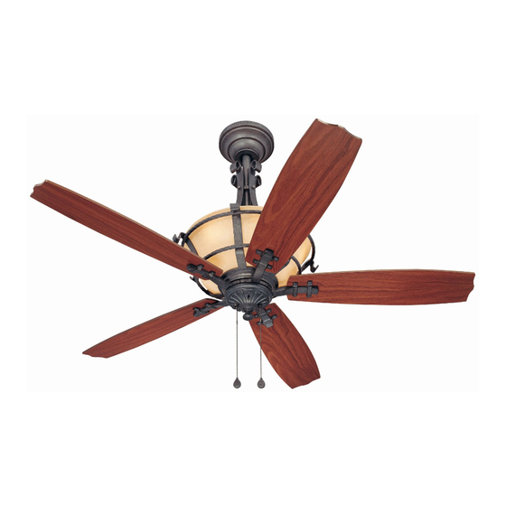
ITEM #0331092
LYNNHAVEN
MODEL #DTA54GPT5CL
Español p. 18
E192641
Publicidad
Capítulos
Tabla de contenido

Manuales relacionados para Harbor Breeze LYNNHAVEN DTA54GPT5CL


Resumen de contenidos para Harbor Breeze LYNNHAVEN DTA54GPT5CL
- Página 1 ITEM #0331092 LYNNHAVEN MODEL #DTA54GPT5CL Harbor Breeze® is a registered trademark of LF, LLC. All Rights Reserved. Español p. 18 ATTACH YOUR RECEIPT HERE Serial Number Purchase Date E192641 Questions, problems, missing parts? Before returning to your retailer, call or contact our...
-
Página 2: Tabla De Contenido
TABLE OF CONTENTS Safety Information ……………………………………………………………...……......2 - 3 Package Contents ……………………………………………………………………..……. 4 Hardware Contents ........................5 Preparation ....….…………………..……………………….…………….………………. 5 Initial Installation ......................6 - 7 Fan Mounting ..........................7 - 8 Wiring ......…………..…………………………………………………...…...8 - 10 Final Installation ……….…………….……………………….………........10 - 12 Lighted Housing Bulb Replacement ………………………………………………….......13 Operation Instructions .....…………………………………………………………....13 -14 Care and Maintenance ……………………………………………..……………......14... -
Página 3: Safety Information
SAFETY INFORMATION WARNINGS To reduce the risk of fire, electrical shock, or personal injury, mount fan to outlet box marked "ACCEPTABLE FOR FAN SUPPORT" and use mounting screws provided with the outlet box. Most outlet boxes commonly used for the support of lighting fixtures are not acceptable for fan support and may need to be replaced. -
Página 4: Package Contents
PACKAGE CONTENTS PART DESCRIPTION QUANTITY PART DESCRIPTION QUANTITY Downrod Motor Screw (preassembled) Canopy Lock Washer Mounting Bracket (preassembled) Motor Housing Decorative Nut Yoke Cover (preassembled) Blade Canopy Mounting Screw Blade Arm (preassembled) Switch Housing Plate Finial Candelabra Base Bulb (preassembled) Switch Housing Pin (preassembled) Pull Chain Extension... -
Página 5: Hardware Contents
HARDWARE CONTENTS (shown actual size) Fiber Blade Screw Blade E3 Wire Washer Connector Qty. 15 Qty. 15 Qty. 4 PREPARATION Before beginning assembly and installation of product, make sure all parts are present. Compare parts with package contents list and hardware contents above. If any part is missing or damaged, do not attempt to assemble, the product. -
Página 6: Initial Installation
INITIAL INSTALLATION Turn off circuit breakers and wall switch to the fan supply line leads. (Fig. 1) DANGER: Failure to disconnect power supply prior to installation may result in serious injury or death. Determine mounting method to use. (Fig. 2) A. -
Página 7: Fan Mounting
INITIAL INSTALLATION Remove motor screws (Q) and lock washers (R) from underside of motor. [If there are plastic motor blocks installed with the motor screws (Q) and lock washers (R), discard the plastic motor blocks.] (Fig. 5) FAN MOUNTING Remove pin (V) and clip (W) from motor housing yoke and loosen set screw. -
Página 8: Wiring
FAN MOUNTING If you decided to cut back the lead wires in Step 3, strip 1/2 of an inch of insulation from end of white wire. Twist stripped ends of each strand of wire within the insulation with pliers. (Fig. 4) Repeat Step 4 for black, blue (if applicable) and green wires. - Página 9 WIRING 1B. FAN CONTROLLED BY PULL CHAIN, LIGHT FAN CONTROLLED BY PULL CHAIN, LIGHT BY WALL SWITCH BY WALL SWITCH: If you intend to control the fan light with a separate wall switch, connect BLACK BLACK wire from fan to BLACK wire from ceiling. Connect BLACK (WALL SWITCH) 120 V Power FROM...
-
Página 10: Final Installation
WIRING IMPORTANT: Using a full range dimmer switch to control fan speed will cause a loud humming noise from fan. To reduce the risk of fire or electrical shock, do NOT use a full range dimmer switch to control fan speed. (Fig. 3) Dimmer Speed Switch... - Página 11 FINAL INSTALLATION Install the six candelabra base 25 watt (max.) bulbs (I) supplied with this fan into the top of the motor housing (D). (Fig. 3) Important: When replacing bulbs, please allow bulb(s) and glass housing (L) to cool down before touching them.
-
Página 12: Switch Housing Plate
FINAL INSTALLATION Remove one screw from fitter plate on underside of motor housing (D) and partially loosen the other two screws. Raise switch housing plate (H) to motor, allowing the male plug from the motor housing (D) to come through the large hole in the switch housing plate (H). -
Página 13: Lighted Housing Bulb Replacement
LIGHTED HOUSING BULB REPLACEMENT IMPORTANT: Allow glass housing (L) and bulb(s) (I) to cool down before touching them. Remove each bulb (I) that has burned out and replace each one with one candelabra base 25-watt max. bulb. Repeat as needed. OPERATION INSTRUCTIONS The pull chain labeled SPEED has four positions to control fan speed. -
Página 14: Care And Maintenance
OPERATION INSTRUCTIONS Use the fan reverse switch, located on the switch housing (J), to optimize your fan for seasonal performance. (Fig. 3) A ceiling fan will allow you to raise your thermostat setting in summer and lower your thermostat setting in winter without feeling a difference in your comfort. -
Página 15: Troubleshooting
TROUBLESHOOTING If you have any questions regarding the product please call customer service at 1-800-527-1292, 8:30 a.m. - 5 p.m., CST, Monday - Friday. Warning: Before beginning work, shut off the power supply to avoid electrical shock. PROBLEM POSSIBLE CAUSE CORRECTIVE ACTION Fan does not move. -
Página 16: Warranty
WARRANTY LIMITED LIFETIME WARRANTY: Litex Industries warrants this fan to be free from defects in workmanship and materials present at time of shipment from the factory for Lifetime limited from the date of purchase. This warranty applies only to the original purchaser. Litex Industries agrees to correct any defect at no charge or, at our option, replace the ceiling fan with a comparable or superior model. -
Página 17: Replacement Parts List
REPLACEMENT PARTS LIST For replacement parts, call our customer service department at 1-800-527-1292, 8:30 a.m. - 5:00 p.m., CST, Monday - Friday. When ordering parts, please have the Model # or Item # of the fan available, which can be found on page 1. PART DESCRIPTION Downrod... -
Página 18: Adjunte Su Recibo Aqui
ARTICULO #0331092 LYNNHAVEN MODELO #DTA54GPT5CL Harbor Breeze® es marca registrada de LF, LLC. Reservados todos los derechos. ADJUNTE SU RECIBO AQUI E192641 Número de serie Fecha de compra ¿Preguntas, problemas, faltan piezas? Antes de regresar a la tienda, llame o póngase en contacto con nuestro departamento de servicio al cliente al 1-800-527-1292, de 8:30 a.m. -
Página 19: Indice De Materias
INDICE DE MATERIAS Información de seguridad ....................19 - 20 Contenido del paquete ......................21 Contenido de artículos de ferretería ..................22 Preparación ....….…………………..……………………….…………….…..…. 22 Instalación inicial ......………………………………………………………………..23 - 24 Montaje del ventilador ..........……............24 - 25 Conexión de los cables .…………………………………………………...…......26 - 27 Instalación final ..………………….……...…….……....……......28 - 30 Reemplazo de bombilla del bastidor iluminado... - Página 20 INFORMACION DE SEGURIDAD ADVERTENCIAS Para reducir el riesgo de incendio, choque eléctrico o daño corporal, sujete el ventilador a una caja de salida marcada "Aceptable para sostener ventilador" ("ACCEPTABLE FOR FAN SUPPORT" en inglés) y use los tornillos de montaje proporcionados con la caja de salida.
-
Página 21: Contenido Del Paquete
CONTENIDO DEL PAQUETE PIEZA DESCRIPCION CANTIDAD PIEZA DESCRIPCION CANTIDAD Vástago Soporte del brazo con voluta Cubierta Tornillo del motor Soporte de montaje (preensamblado) Bastidor del motor Arandela de seguridad (preensamblada) Cubierta del yugo Tuerca decorativa Paleta (preensamblada) Brazo para la paleta Tornillo para montaje de la Placa de la caja del cubierta (preensamblado) -
Página 22: Contenido De Artículos De Ferretería
CONTENIDO DE ARTICULOS DE FERRETERIA (se muestra en tamaño natural) Tornillo Arandela para la de fibra paleta para la Conector paleta para cable Ctd. 15 Ctd. 15 Ctd. 4 PREPARACION Antes de empezar con el ensamblaje e instalación del producto, asegúrese de tener todas las piezas. -
Página 23: Instalación Inicial
INSTALACION INICIAL Apague todos los disyuntores del circuito y el interruptor de pared a la línea de suministro de electricidad del ventilador. (Fig. 1) PELIGRO: El no desconectar el suministro de electricidad antes de la instalación puede resultar en daños graves o la muerte. Determine el método de montaje. -
Página 24: Montaje Del Ventilador
INSTALACION INICIAL 5. Saque los tornillos del motor (Q) y las arandelas de seguridad (R) del lado inferior del motor. [Si hay también soportes de plástico del motor instalados con los tornillos del motor (Q) y las arandelas de seguridad (R), deseche los soportes de plástico.] (Fig. - Página 25 MONTAJE DEL VENTILADOR Dependiendo del largo del vástago (A) que use, es posible que tenga que cortar los cables principales para facilitar la conexión de cables. Si usted elige cortar los cables principales, se le sugiere hacerlo de la manera que sigue: bola Toma los cables principales y asegúrese de que los haya jalado completamente por la parte...
-
Página 26: Conexión De Los Cables
CONEXION DE LOS CABLES ADVERTENCIA: Para reducir el riesgo de incendio, choque eléctrico o daño corporal, los conectores para cable provistos con este ventilador son diseñados para aceptar sólo un cable de calibre 12 de la casa y dos cables principales del ventilador. - Página 27 CONEXION DE LOS CABLES 1C. VENTILADOR Y LUZ CONTROLADOS POR VENTILADOR Y LUZ CONTROLADOS POR DOS INTERRUPTORES DE PARED DOS INTERRUPTORES DE PARED: Si usted piensa controlar la luz y el ventilador con interruptores NEGRO (INTERRUPTOR DE PARED) distintos, conecte el cable NEGRO del ventilador al 120 V cables (INTERRUPTOR DE PARED para la LUZ) de corriente...
-
Página 28: Instalación Final
INSTALACION FINAL Si es necesario, parcialmente afloje los dos tornillos para montaje de la cubierta (T) en la parte inferior del soporte de montaje (C) que se alinean con los agujeros en la cubierta (B). Eleve la cubierta (B) hasta el soporte de montaje (C). - Página 29 INSTALACION FINAL Quite un tornillo del aro exterior en la parte inferior del bastidor del motor (D) y afloje los otros dos tornillos parcialmente. Coloque el bastidor de vidrio (L) cuidadosamente dentro de la ranura en el fondo de la caja del bastidor de vidrio (M). Suba el bastidor de vidrio (L) y la caja del bastidor de vidrio (M) hacia el bastidor del motor (D) hasta que el bastidor de vidrio (L) y la caja del bastidor de vidrio (M) toquen la...
- Página 30 INSTALACION FINAL Quite un tornillo de la placa de conexión en la parte inferior del bastidor del motor (D) y afloje los otros dos tornillos parcialmente. Levante la placa de la caja del interruptor (H) al motor, dejando que el enchufe macho del bastidor del motor (D) pase por agujero grande en la placa de la caja del interruptor (H).
-
Página 31: Reemplazo De Bombilla Del Bastidor Iluminado
REEMPLAZO DE BOMBILLA DEL BASTIDOR ILUMINADO IMPORTANTE: Permita que se enfríen el bastidor de vidrio (L) y la(s) bombilla(s) (I) antes de tocarlos. Quite cada bombilla (I) que se haya fundido y reemplace cada una con una bombilla de base candelabro de 25 vatios máx. -
Página 32: Instrucciones De Funcionamiento
INSTRUCCIONES DE FUNCIONAMIENTO Use el interruptor de reversa, localizado en la caja del interruptor, para optimizar el uso del ventilador durante las estaciones del año. (Fig. 3) Un ventilador de techo le permitirá subir el termostato en verano y bajarlo en invierno sin notar una diferencia en su comodidad. -
Página 33: Localización De Fallas
LOCALIZACION DE FALLAS Si tiene alguna pregunta acerca del producto, por favor llame al servicio al cliente al 1-800-527-1292, de 8:30 a.m. a 5:00 p.m., hora central, de lunes a viernes. ADVERTENCIA: Antes de proseguir, desconecte la electricidad, quitando los fusibles o cortando el suministro de energía de los circuitos para evitar un choque eléctrico. -
Página 34: Garantía
LOCALIZACION DE FALLAS PROBLEMA CAUSA POSIBLE ACCION CORRECTIVA El ventilador funciona 1. No se instalaron bien la(s) 1. Instale la(s) bombilla(s) de pero la luz no. bombilla(s). nuevo. 2. No se conectaron correctamente 2. Verifique que se conectaron cables en la cubierta (B). bien los cables en la cubierta (B) y, si es necesario, vuelva a conectar- los según las instrucciones en las... -
Página 35: Lista De Piezas De Repustos
LISTA DE PIEZAS DE REPUESTOS Para piezas de repuesto, llame a nuestro departamento de servicio al cliente al 1-800-527-1292, de 8:30 a.m. a 5:00 p.m., hora central, de lunes a viernes. Al pedir piezas, por favor tenga listo el No. de modelo o No.