Tabla de contenido
Publicidad
Idiomas disponibles
Idiomas disponibles
Enlaces rápidos
Installation, use and maintenance instructions
Instrucciones de instalación, montaje y funcionamiento
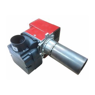
Light oil burners
GB
Quemadores de gasóleo
E
One stage operation
Funcionamiento a 1 llama
MODEL - MODELO
20091750
20091751
20091752
CODE - CÓDIGO
RDB2.2R BG 15 kW
RDB2.2R BG 24 kW
RDB2.2R BG 32 kW
TYPE - TIPO
L002BG1
L003BG2
L004BG3
20094184 (6) - 06/2015
Publicidad
Capítulos
Tabla de contenido

Manuales relacionados para Riello RDB2.2R BG


Resumen de contenidos para Riello RDB2.2R BG
- Página 1 Light oil burners Quemadores de gasóleo One stage operation Funcionamiento a 1 llama MODEL - MODELO CODE - CÓDIGO TYPE - TIPO 20091750 RDB2.2R BG 15 kW L002BG1 20091751 RDB2.2R BG 24 kW L003BG2 20091752 RDB2.2R BG 32 kW L004BG3...
- Página 2 Translation of the original instructions Traducción de las instrucciones originales...
-
Página 3: Tabla De Contenido
Contents Declaration..................3 Information and general warnings. - Página 4 Contents 6.11.16 Checking the electronic circuit controlling the oil valve..........21 6.11.17 EEprom check.
-
Página 5: Declaration
The quality is guaranteed by a quality and management system certified in accordance with UNI EN ISO 9001. Legnago, 21.05.2015 Executive General Manager Research & Development Director RIELLO S.p.A. - Burner Department RIELLO S.p.A. - Burner Department Mr. U. Ferretti Mr. F. Comencini... -
Página 6: Information And General Warnings
Information and general warnings Information and general warnings Information about the instruction manual 2.1.1 Introduction DANGER: EXPLOSION The instruction manual supplied with the burner: This symbol signals places where an explosive at- is an integral and essential part of the product and must not mosphere may be present. -
Página 7: Delivery Of The System And The Instruction Manual
Information and general warnings The system supplier must carefully inform the user about: 2.1.4 Delivery of the system and the instruction – the use of the system; manual – any further tests that may be required before activating the When the system is delivered, it is important that: system;... -
Página 8: Safety And Prevention
Safety and prevention Safety and prevention Introduction The burners have been designed and built in compliance with the type and pressure of the fuel, the voltage and frequency of the current regulations and directives, applying the known technical electrical power supply, the minimum and maximum deliveries for rules of safety and envisaging all the potential danger situations. -
Página 9: Technical Description Of The Burner
Technical description of the burner Technical description of the burner Technical data Model L002 BG1 L003 BG2 L004 BG2 Delivery kg/h 1.26 2.02 Thermal output Fuel Light oil, viscosity 4 6 mm /s at 20°C Electrical supply Single-phase, ~ 50Hz 230V ± 10% Motor 0.75 2800... -
Página 10: Overall Dimensions
Technical description of the burner Overall dimensions Flange Burner 20100061 Fig. 2 Type L002 BG1 L003 BG1 L004 BG1 Burner equipment Flange with insulating gasket ..........No. 1 Nuts for fixing the flange to the boiler ......... No. 5 Screw and nuts for flange ..........No. 1 Screws for fixing the flange to the boiler ...... -
Página 11: Installation
Installation Installation Notes on safety for the installation After carefully cleaning all around the area where the burner is to The installation of the burner must be carried out be installed, and arranging for the environment to be illuminated by qualified personnel, as indicated in this manual correctly, proceed with the installation operations. -
Página 12: Operating Position
Installation Operating position The burner is designed to operate only in the po- Any other positioning could compromise the cor- sitions 1, 2, 3 and 4. rect operation of the appliance. Installation 1 is preferable, as it is the only one that The installation 5 is prohibited for safety reasons. -
Página 13: Burner Assembly
Installation Burner assembly BF application The temperature of the incoming air must not exceed 70°C. CAUTION For correct BF application, the burner must be in- stalled on an appropriate BF boiler. WARNING In case of applying BF (Fig. 7), the air supply takes place by means of a flexible hose connected to the air intake (A). -
Página 14: Priming Pump
Installation 5.7.2 Priming pump In the system of Fig. 9 just loosen the connection of the vacume- ter 6)(Fig. 8) and wait for the fuel to come out. D1842 D5741 Fig. 10 Fig. 9 L metres metres Ø (8 mm) Ø... -
Página 15: Start-Up, Calibration And Operation Of The Burner
Start-up, calibration and operation of the burner Start-up, calibration and operation of the burner Notes on safety for the first start-up The first start-up of the burner must be carried out Check the correct working of the adjustment, com- by qualified personnel, as indicated in this manual mand and safety devices. -
Página 16: Air Damper Adjustment
Start-up, calibration and operation of the burner Air damper adjustment The air damper is adjusted in the factory. 20091750 This adjustment is purely indicative. However, each installation has its own operating conditions: nozzle flow rate, positive or negative pressure in the combustion chamber, air excess re- quirement, etc. -
Página 17: Electrodes Setting
Start-up, calibration and operation of the burner Electrodes setting These dimensions Fig. 14 must be respected. WARNING 20093889 Fig. 14 Fuel heating The burner uses a heater powered by the presence of electricity to the boiler. At first start-up, during the winter period and with a light-oil tem- perature less than 8 °C, some ignition difficulties could occur be- cause the fuel is not warm enough. -
Página 18: Electrical System
Start-up, calibration and operation of the burner Electrical system Notes on safety for the electrical wiring The electrical wiring must be carried out with the electrical supply disconnected. The electrical wiring must be carried out in conformity with the regulations in force in the countries of destination, and by qualified personnel. -
Página 19: Electrical Diagram
Start-up, calibration and operation of the burner Electrical diagram ~ 50Hz - 230V Key (Fig. 16) C: Capacitor E: Electrodes F: UV detector Main switch F1: T4A Fuse HT: Heat request thermostat K: Pre-heater thermostat MV: Fan motor R: Pre-heater RR: Remote reset SB: Remote lockout signal (230V - 0.5A max.) TB: Burner-earth... -
Página 20: Operating Programme
Start-up, calibration and operation of the burner 6.10 Operating programme Normal operation Lockout due to ignition failure POWER SUPPLY POWER SUPPLY Lockout Green blink Orange Green Green blink blink blink Green Orange Green blink blink Flame loss during operation (Recycle: max. 3 attempts) D11374 Fig. -
Página 21: Table Of Times
Start-up, calibration and operation of the burner 6.11 Table of times Symbol Description Value (sec.) Standby: the burner is waiting for a heat request 1 Standby time for an input signal: reaction time, control box remains in waiting status for t1 Initialisation standby time: check time following the main power start-up Checks extraneous light during t2: waiting mode for t2l, then lockout: the motor does not start Oil pre-heating time : waiting status for t2p, after goes into lockout... -
Página 22: Fuel Preheating Function
Start-up, calibration and operation of the burner 6.11.3 Fuel preheating function 6.11.7 Presence of an extraneous light or parasite flame The burner is equipped with the fuel pre-heating function, in the presence of a start request from the heat request thermostat of The presence of the parasite flame or the extraneous light can be the boiler, the burner awaits the closure of the start-up thermostat detected in the stand-by condition when the burner is stopped... -
Página 23: Reset Protection
Start-up, calibration and operation of the burner 6.11.9 Reset protection 6.11.14 Internal voltage anomaly The burner can be released by pressing, for at least 0.4 seconds, The control-box automatically detects if the internal voltage the reset button integrated in the control box and the unlocking works correctly. -
Página 24: Automatic Pre-Heating Deactivation
Start-up, calibration and operation of the burner 6.12 Automatic pre-heating deactivation It is possible to disable the pre-heater function in automatic When the pre-heating is disabled, the pre-heating remains off mode by pressing the reset button of the control box or the re- until: mote reset. -
Página 25: Programming Menu
Start-up, calibration and operation of the burner 6.14 Programming menu GENERAL If the number of presses on the reset or remote reset button ex- ceeds the maximum allowable, the value that stays in memory The programming menu can be accessed via the integrated reset will be the maximum one. -
Página 26: Shut-Down Test
Start-up, calibration and operation of the burner 6.14.1 Shut-down test 6.14.3 Intermittent operation Sequence for shut-down test programming Sequence for enable/disable Programming allowed in OPERATING mode and in STAND- Programming allowed in OPERATING mode and in STAND- Press push-button for 5 sec. t < 10 sec. ... -
Página 27: Lockout Types
Start-up, calibration and operation of the burner 6.15 Lockout types Whenever a lockout occurs, the control box shows the reasons LED in the reset button identifies the possible types of fault, which for the fault (and the reasons can be identified by the reset button are listed in the table below colour). -
Página 28: Faults / Solutions
Faults / Solutions Faults / Solutions Here below you can find some causes and the possible solutions When lockout lamp comes on the burner will attempt to light only for some problems that could cause a failure to start or incorrect after pushing the reset or remote reset button. -
Página 29: Maintenance
Maintenance Maintenance Notes on safety for the maintenance The periodic maintenance is essential for the good operation, safety, yield and duration of the burner. Disconnect the electrical supply from the burner It allows you to reduce consumption and polluting emissions and by means of the main system switch. - Página 31 Índice Declaración ..................3 Información y advertencias generales .
- Página 32 Índice 6.11.16 Control del circuito electrónico de mando de la válvula de aceite ........21 6.11.17 Comprobación EEprom.
-
Página 33: Declaración
La calidad está garantizada mediante un sistema de calidad y management certificado según UNI EN ISO 9001. Legnago, 21.05.2015 Director general Director Investigación y Desarrollo RIELLO S.p.A. - Dirección Quemadores RIELLO S.p.A. - Dirección Quemadores Ing. U. Ferretti Ing. F. Comencini... -
Página 34: Información Y Advertencias Generales
Información y advertencias generales Información y advertencias generales Información sobre el manual de instrucciones 2.1.1 Introducción ATENCIÓN ÓRGANOS EN MOVIMIENTO El manual de instrucción entregado como suministro del quema- Este símbolo proporciona informaciones para evi- dor: tar el acercamiento de las extremidades a órga- ... -
Página 35: Entrega De La Instalación Y Del Manual De Instrucción
Información y advertencias generales El proveedor de la instalación informe con precisión al usua- 2.1.4 Entrega de la instalación y del manual de rio acerca de: instrucción – el uso de la instalación, En ocasión de la entrega de la instalación es necesario que: –... -
Página 36: Seguridad Y Prevención
Seguridad y prevención Seguridad y prevención Introducción Los quemadores fueron diseñados y fabricados en conformidad mos con los cuales está regulado el quemador, la presurización de con las normas y directivas vigentes, aplicando las regulaciones la cámara de combustión, las dimensiones de la cámara de com- técnicas de seguridad conocidas y previendo todas las situacio- bustión, la temperatura ambiente, deben estar comprendidos den- nes de peligro potenciales. -
Página 37: Descripción Técnica Del Quemador
Descripción técnica del quemador Descripción técnica del quemador Datos técnicos Modelo L002 BG1 L003 BG2 L004 BG2 Caudal kg/h 1.26 2.02 Potencia térmica Combustible Gasóleo, viscosidad 4 6 mm /seg a 20º C Alimentación eléctrica Monofásica, ~ 50Hz 230 V ± 10% Motor 0,75 2800... -
Página 38: Dimensiones
Descripción técnica del quemador Dimensiones Quemador Brida 20100061 Fig. 2 Tipo L002 BG1 L003 BG1 L004 BG1 Material suministrado en dotación Brida con protección aislante ..........N° 1 Tuercas para brida de fijación a la caldera ......N° 5 Tornillo y tuerca para brida ..........N° 1 Tornillos para brida de fijación a la caldera ...... -
Página 39: Instalación
Instalación Instalación Notas sobre la seguridad para la instalación Después de realizar una cuidadosa limpieza en toda el área de El quemador debe ser instalado por personal ha- la instalación del quemador y de proveer una correcta ilumina- bilitado según todo lo indicado en el presente ma- ción del ambiente, proceder con las operaciones de instalación. -
Página 40: Posición De Funcionamiento
Instalación Posición de funcionamiento El quemador está preparado para funcionar ex- Cualquier otro posicionamiento podría compro- clusivamente en las posiciones 1, 2, 3 y 4. meter el buen funcionamiento del aparato. Es conveniente escoger la instalación 1 puesto La instalación 5 está prohibida por motivos de se- ATENCIÓN ATENCIÓN que es la única que permite el mantenimiento tal... -
Página 41: Montaje Del Quemador
Instalación Montaje del quemador Aplicación BF La temperatura del aire aspirado no debe su- perar los 70° C. PRECAUCIÓN Para una correcta aplicación BF, el quemador debe instalarse en una caldera BF apropiada. ATENCIÓN Si se aplica el BF (Fig. 7), el aire ingresa a través del tubo flexible conectado con la toma de aire (A). -
Página 42: Cebado De La Bomba
Instalación 5.7.2 Cebado de la bomba En la instalación de la Fig. 9, es suficiente aflojar la conexión del vacuómetro 6) (Fig. 8) y esperar la salida del combustible. D1842 D5741 Fig. 10 Fig. 9 L metros metros Ø (8 mm) Ø... -
Página 43: Puesta En Funcionamiento, Calibración Y Funcionamiento Del Quemador
Puesta en funcionamiento, calibración y funcionamiento del quemador Puesta en funcionamiento, calibración y funcionamiento del quemador Notas sobre la seguridad para la primera puesta en funcionamiento La primera puesta en funcionamiento del quema- Comprobar el correcto funcionamiento de los dis- dor debe ser realizada por personal habilitado se- positivos de regulación, mando y seguridad. -
Página 44: Regulación Registro De Aire
Puesta en funcionamiento, calibración y funcionamiento del quemador Regulación registro de aire El registro de aire se regula en fábrica. 20091750 Esta regulación es puramente indicativa. Cada instalación tiene las propias condiciones de funcionamiento: caudal de la boquilla, presión positiva o negativa en la cámara de combustión, necesi- dad de exceso de aire, etc. -
Página 45: Regulación Electrodos
Puesta en funcionamiento, calibración y funcionamiento del quemador Regulación electrodos Respetar las medidas de la Fig. 14. ATENCIÓN 20093889 Fig. 14 Calentamiento del combustible El quemador utiliza un calentador alimentado por la tensión pre- sente en la caldera. En el primer arranque, durante la temporada invernal y con tempe- ratura del gasóleo inferior a 8 ºC, el encendido puede ser dificulto- so porque el combustible no está... -
Página 46: Instalación Eléctrica
Puesta en funcionamiento, calibración y funcionamiento del quemador Instalación eléctrica Notas sobre la seguridad para las conexiones eléctricas Las conexiones eléctricas se deben llevar a cabo con la alimentación eléctrica desconectada. Las conexiones eléctricas se deben realizar según las normas vigentes del país de destino y por personal cualifi- cado. -
Página 47: Esquema Eléctrico
Puesta en funcionamiento, calibración y funcionamiento del quemador Esquema eléctrico ~ 50Hz - 230V Leyenda (Fig. 16) C: Condensador E: Electrodos F: Sensor llama UV Interruptor general F1: T4A Fusible HT: Termostato de solicitud de calor K: Termostato de aprobación de arranque después del pre-calentamiento MV: Motor ventilador R: Calentador... -
Página 48: Programa De Funcionamiento
Puesta en funcionamiento, calibración y funcionamiento del quemador 6.10 Programa de funcionamiento Funcionamiento normal Bloqueo por falta de encendido ALIMENTACIÓN ALIMENTACIÓN Bloqueo Parpadeo verde Parpadeo Parpadeo Parpadeo anaranjado verde verde Verde Parpadeo Parpadeo anaranjado verde Rojo Pérdida de llama durante el funcionamiento (Reciclado: máx. 3 intentos) D11374 Fig. -
Página 49: Tabla De Los Tiempos
Puesta en funcionamiento, calibración y funcionamiento del quemador 6.11 Tabla de los tiempos Símbolo Descripción Valor (seg) En modo espera: El quemador espera la solicitud de calor Tiempo de espera para una señal de entrada: tiempo de reacción, la caja de control permanece en ... -
Página 50: Función De Pre-Calentamiento Del Combustible
Puesta en funcionamiento, calibración y funcionamiento del quemador 6.11.3 Función de pre-calentamiento del combustible 6.11.7 Presencia de luz extraña o llama parásita El quemador posee la función de pre-calentamiento del combus- La presencia de llama parásita o de luz extraña se puede detec- tible, en caso de una solicitud de funcionamiento del termostato tar en el estado de standy-by cuando el quemador está... -
Página 51: Protección De Desbloqueo
Puesta en funcionamiento, calibración y funcionamiento del quemador 6.11.9 Protección de desbloqueo 6.11.14 Anomalía en la tensión interna El quemador se puede desbloquear presionando el pulsador de La caja de control detecta automáticamente si la tensión interna desbloqueo integrado en la caja de control durante al menos 0,4 funciona correctamente. -
Página 52: Desactivación Automática Del Pre-Calentamiento
Puesta en funcionamiento, calibración y funcionamiento del quemador 6.12 Desactivación automática del pre-calentamiento Es posible deshabilitar la función del pre-calentamiento en Cuando el pre-calentamiento se encuentra deshabilitado, el modo automático presionando el pulsador del desbloqueo de la pre-calentamiento permanece apagado hasta: caja de control o el desbloqueo a distancia. -
Página 53: Menú De Programación
Puesta en funcionamiento, calibración y funcionamiento del quemador 6.14 Menú de programación NOTAS GENERALES máticamente de la página y un led verde parpadeará en el valor configurado. Se puede acceder al menú programación mediante el pulsador de desbloqueo integrado o a distancia, durante el FUNCIONA- Si el número de presiones en el pulsador de desbloqueo integra- MIENTO y en STAND-BY. -
Página 54: Ensayo De Apagado
Puesta en funcionamiento, calibración y funcionamiento del quemador 6.14.1 Ensayo de apagado 6.14.3 Funcionamiento intermitente Secuencia para ensayo de apagado Secuencia para habilitar/deshabilitar Programación permitida en modo de FUNCIONAMIENTO y Programación permitida en modo de FUNCIONAMIENTO y en STAND-BY. en STAND-BY. -
Página 55: Tipos De Bloqueo
Puesta en funcionamiento, calibración y funcionamiento del quemador 6.15 Tipos de bloqueo En la pantalla de la caja de control se produce un mal funciona- led en el pulsador de desbloqueo emitida por la caja de control miento cada vez que se produce un bloqueo, identificado por el identifica los posibles tipos de desperfectos, que se listan en la color de pulsador de desbloqueo. -
Página 56: Anomalías / Soluciones
Anomalías / Soluciones Anomalías / Soluciones A continuación se detallan algunas causas y posibles soluciones Cuando se enciende el testigo de bloqueo, el quemador se pon- para algunos problemas que pudieran causar una falla en el en- drá en funcionamiento solo después de haber presionado el pul- cendido o un funcionamiento incorrecto del quemador. -
Página 57: Mantenimiento
Mantenimiento Mantenimiento Notas sobre la seguridad para el mantenimiento El mantenimiento periódico es fundamental para el buen funcio- namiento, la seguridad, el rendimiento y la duración del quema- Cortar la alimentación eléctrica del quemador con dor. el interruptor general de la instalación. El mismo permite reducir los consumos, las emisiones contami- PELIGRO nantes y mantener el producto fiable a través del tiempo. - Página 60 RIELLO S.p.A. I-37045 Legnago (VR) Tel.: +39.0442.630111 http:// www.riello.it http:// www.riello.com Subject to modifications - Sujeto a modificaciones...