Tabla de contenido
Publicidad
Idiomas disponibles
Idiomas disponibles
Enlaces rápidos
READ AND SAVE THESE INSTRUCTIONS
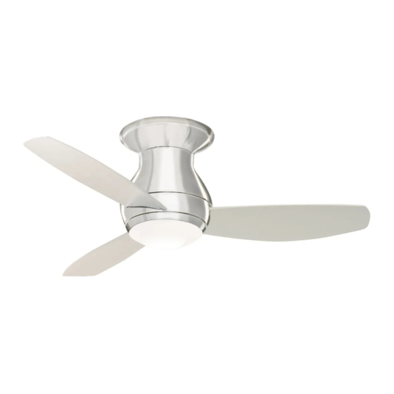
CURVA SKY LED INDOOR
44" & 52" Snugger Ceiling Fan
44" Model Number
CF145LBS00
Brushed Steel
Net Weight:
Questions, problems, missing parts: Before returning to the store call
Emerson Electric Customer Service - 8 a.m. - 6 p.m., Eastern, Monday-Friday
Part No. F40BP75380000
Revision: 171110
Owner's Manual
18.5
Lbs.
1-800-654-3545
www.emersonfans.com
52" Model Number
CF153LBS00
Brushed Steel
19.4
Net Weight:
U.L. Model No.: CF145L & CF153L
Lbs.
• Español - página 25
• Français - page 51
Form No. BP7538
Publicidad
Capítulos
Tabla de contenido
Solución de problemas

Manuales relacionados para Emerson CF145LBS00


Resumen de contenidos para Emerson CF145LBS00
- Página 1 Lbs. Net Weight: Lbs. Questions, problems, missing parts: Before returning to the store call Emerson Electric Customer Service - 8 a.m. - 6 p.m., Eastern, Monday-Friday • Español - página 25 1-800-654-3545 • Français - page 51 Part No. F40BP75380000 Form No.
-
Página 2: Tabla De Contenido
UC8013R, manufactured by Rhine Electric Co., Ltd. 1. To avoid possible shock, be sure electricity is turned off To avoid fire, shock or injury, do not use an Emerson or at the fuse box before wiring, and do not operate fan any other brand of control not specifically approved for without blades. -
Página 3: Unpacking Instructions
1. Unpacking Instructions PACKAGE CONTENTS Part Fan Motor Assembly Description Quantity Ceiling Trim Ring Ceiling Mounting Plate Fan Blades Lower Housing LED Light Fixture Assembly Glass No-Light Cover 6-Speed Electronic Receiver Control with Parts Bag 6-Speed Handheld Transmitter with Wall Bracket PROTECTIVE Remove the fan motor PLASTIC BAG... -
Página 4: Electrical Requirements
This Manual Is Designed to Make it as Easy as Possible for You to Assemble, Install, Operate and Maintain Your Ceiling Fan Tools Needed for Assembly Your Emerson ceiling fan comes supplied with a Fan/Light Remote Control which consists of a receiver mounted One Phillips Head Screwdriver One Stepladder inside the ceiling cover of the fan motor housing. -
Página 5: Ceiling Fan Assembly
3. Ceiling Fan Assembly M5 x 16 mm FLANGE HEAD BLADE SCREWS (3 per blade) FAN BLADE SLIDE FAN BLADE INTO BLADE CENTER SLOT FAN MOTOR WARNING ASSEMBLY To reduce the risk of personal injury, do not bend the blades during installation, balancing the blades or BLADE SLOT Figure 1 cleaning the fan. - Página 6 3. Ceiling Fan Assembly (Continued) Remove one of the three M4 x 10 mm Pan Head Screws in the Lower Housing and loosen the remaining two LED LIGHT FIXTURE screws. ASSEMBLY Retain the M4 x 10 mm Pan Head Screw for future use. Tuck wires into the LED Light Fixture Assembly and position in the Lower Housing Assembly.
-
Página 7: How To Hang Your Ceiling Fan
WARNING CEILING The fan must be hung with at least 7' of clearance from floor to blades (Figure 6). WARNING Turning off wall switch is not sufficient. To avoid possible electrical shock, be sure electricity is turned off at the main fuse box before wiring. - Página 8 Slide the Ceiling Trim Ring over the Fan Motor Assembly and let it rest on the Fan Motor Assembly (Figure 8). FAN MOTOR ASSEMBLY CEILING TRIM RING Figure 8 Place the Fan Motor Assembly onto the Ceiling Mounting Plate Hook during wiring Fan Motor Assembly to Outlet Box (Figure 9).
-
Página 9: How To Wire Your Ceiling Fan
5. How to Wire Your Ceiling Fan If you feel that you do not have enough electrical CAUTION: To reduce the risk of electrical shock, wiring knowledge or experience, have your fan disconnect the electrical supply circuit before installed by a licensed electrician. installing the fan, light kit or receiver. - Página 10 5. How to Wire Your Ceiling Fan (Continued) Securely connect the Supply White Wire (neutral) to the MOUNTING Receiver White Wire (AC IN N)/(TO MOTOR N) and White PLATE Fan Wire (neutral) using a Wire Connector (Figure 12). SUPPLY WHITE WIRE WIRE CONNECTOR RECEIVER...
- Página 11 5. How to Wire Your Ceiling Fan (Continued) Securely connect the Fan Motor Black Wire to the Receiver Black Wire (TO MOTOR L) using a Wire Connector (Figure 15). FAN BLACK WIRE WIRE CONNECTOR RECEIVER BLACK WIRE RECEIVER Figure 15 WARNING Check to see that all connections are tight, including RECEIVER...
- Página 12 5. How to Wire Your Ceiling Fan (Continued) Remove and retain one of the four M5 x 10 mm Pan Head M5 x 10 mm PAN HEAD Ceiling Cover Screws and Split Washers in the Ceiling CEILING CEILING COVER SCREW Mounting Plate.
-
Página 13: Final Assembly
6. Final Assembly Place the Glass into the opening in the Lower Housing, aligning the three Flat Areas on the top edge of the Glass with the three raised Dimples on the Lower Housing and turn the Glass clockwise until it stops (Figure 19). NOTE: Periodically check that the Glass is seated fully clockwise in the Lower Housing. -
Página 14: Optional Installation Of No-Light Cover
7. Optional Installation of No-Light Cover NOTE: To use the No-Light Cover, the LED Light Fixture Assembly MUST NOT Be Installed, or the LED Light Fixture Assembly MUST Be Removed. WARNING Turning off wall switch is not sufficient. To avoid possible electrical shock, be sure electricity is turned off at the main fuse box before wiring. - Página 15 7. Optional Installation of No-Light Cover (Continued) Disconnect the LED Light Fixture Assembly wire terminals from the Fan Motor Assembly wire terminals. (Figure 22). Store the LED Light Fixture Assembly in a safe location for future installation. Tuck the Fan Motor Assembly wires and connectors into the Lower Housing prior to assembling the No-Light Cover.
-
Página 16: Remote Control Procedures
8. Remote Control Procedures 8.1: Preset Memory Feature Your Emerson receiver is equipped with a preset memory When the switch is turned back ON the light and fan will feature. If the AC supply to the receiver is powered resume operation as they we re prior to the switch being through a wall switch, when the switch is turned OFF, turned OFF. - Página 17 8. Remote Control Procedures (Continued) Your Emerson Ceiling Fan/Light Remote Control consists of Hand-Held Transmitter and a Receiver which is mounted under the Fan Ceiling Cover. POWER INDICATOR When power is restored, push and hold the fan OFF LIGHT Button ( ) for 3 to 5 seconds to set the code in the Receiver (Figure 26).
- Página 18 8. Remote Control Procedures (Continued) To turn the downlight on, press and release the ( Button. The light will turn on at the light intensity previously selected (Figure 28). POWER INDICATOR LIGHT To vary the intensity of the light, hold the ( ) Button down until the desired light intensity is reached, then release the Button (Figure 28).
-
Página 19: Maintenance
Emerson Electric Co. Substitution of parts or accessories not designated • Slope Ceiling Kit for use with this product by Emerson Electric Co. could result in personal injury or property damage. WARNING The use of any other control not specifically approved for this fan could result in fire, shock and personal injury. -
Página 20: Repair Parts
11. Repair Parts PARTS BAG 8 - 52" 9 - 44" U.L. Model No.: CF145L & CF153L... - Página 21 11. Repair Parts Listing Part Numbers Model No. Model No. Ceiling Mounting Plate 763987 763987 Description CF145LBS00 CF153LBS00 Ceiling Trim Ring 763989-BS 763989-BS Ceiling Cover 763988-BS 763988-BS Lower Housing 764917-BS 764917-BS LED Light Fixture Assembly 764918 764918 Glass 763994-OM 763994-OM...
-
Página 22: Troubleshooting
If ceiling height allows, install the fan 8 - 9 feet could be realized with this simple step! above the floor for optimal airflow. Consult your Emerson Turn Off When Not in the Room. Ceiling fans cool people, Retailer for optional mounting accessories. -
Página 23: Ceiling Fan Limited Warranty
What We Will Do To Correct Problems: If the defect is covered by this limited warranty, Emerson will repair or replace the applicable Emerson Ceiling Fan Product at no charge to You. If repair of the Emerson Ceiling Fan Product is not practical or possible within a reasonable time and no replacement Emerson Ceiling Fan Product can be provided, Emerson will refund You the actual purchase price of Your Emerson Ceiling Fan Product. - Página 24 The date code of this fan may be found on the box, stamped in ink on a white label. You should record this data above and keep it in a safe place for future use. Air Comfort Products DIVISION OF EmErSON ElEctrIc cO. 8100 W. Florissant • St. louis, mO 63136 Questions, problems, missing parts: Before returning to the store call Emerson Electric Customer Service 8 a.m.
-
Página 25: Spanish
19,4 Peso neto: Peso neto: Preguntas, problemas, piezas faltantes: Antes de devolver el producto a la tienda, llame al Servicio al Cliente de Emerson Electric 8 a.m. a 6 p.m., Hora del Este, lunes a viernes 1-800-654-3545 • Français – page 49 www.emersonfans.com... -
Página 26: Instrucciones De Seguridad
Para evitar incendios, descargas eléctricas o lesiones, no utilice un 1. Para evitar posibles descargas eléctricas, asegúrese de que la control Emerson o de cualquier otra marca que no esté aprobado electricidad esté desconectada en la caja de fusibles antes de específicamente para este ventilador. -
Página 27: Instrucciones De Desempaquetado
Emerson Electric Co. para utilizarse con Cubierta sin luz este producto. La sustitución con piezas o accesorios no diseñados por Emerson Electric Co. para utilizarse con este Control del receptor electrónico de producto podría causar lesiones corporales o daños materiales. -
Página 28: Herramientas Necesarias Para El Ensamblaje
Emerson Electric ADVERTENCIA suministrado con el ventilador. -
Página 29: Ensamblaje Del Ventilador De Techo
3. Ensamblaje del ventilador de techo TORNILLOS CON CABEZA M5 x 16mm FLANGE HEAD PALETA DEL DE PESTAÑA PARA PALETA BLADE SCREWS (3 per blade) FAN BLADE Ponga el ensamblaje del motor del ventilador en posición invertida VENTILADOR M5 x 16 mm (3 por paleta) en preparación para el montaje de las tres paletas del ventilador. - Página 30 3. Ensamblaje del ventilador de techo (continuación) ENSAMBLAJE DEL Retire uno de los tres tornillos de cabeza troncocónica M4 x 10 mm LED LIGHT ACCESORIO DE FIXTURE ubicados en la carcasa inferior y afloje los dos tornillos restantes. ILUMINACIÓN LED ASSEMBLY Retenga el tornillo de cabeza troncocónica M4 x 10 mm para uso futuro.
-
Página 31: Cómo Colgar Su Ventilador De Techo
4. Cómo colgar su ventilador de techo ADVERTENCIA CEILING TECHO El ventilador se debe colgar con por lo menos 7 pies de holgura desde el piso hasta las paletas (Figura 6). ADVERTENCIA POR LO No basta con poner el interruptor de pared en la posición de LEAST MENOS apagado. - Página 32 4. Cómo colgar su ventilador de techo (continuación) Deslice al anillo embellecedor del techo sobre el ensamblaje del ENSAMBLAJE FAN MOTOR DEL MOTOR motor del ventilador y deje que descanse sobre el ensamblaje del ASSEMBLY DEL VENTILADOR motor (Figura 8). CEILING ANILLO TRIM RING...
-
Página 33: Cómo Cablear Su Ventilador De Techo
5. Cómo cablear su ventilador de techo Si le parece que no tiene suficientes conocimientos o experiencia PRECAUCIÓN: Para reducir el riesgo de descargas eléctricas, en cableado eléctrico, haga que un electricista con licencia desconecte el circuito de suministro eléctrico antes de instalar el instale su ventilador. - Página 34 5. Cómo cablear su ventilador de techo (continuación) MOUNTING PLACA DE PLATE MONTAJE Conecte firmemente el cable blanco de suministro (neutro) al CABLE BLANCO cable blanco del receptor (ENTRADA CA N)/(AL MOTOR N) y el SUPPLY DE SUMINISTRO WHITE WIRE cable blanco del ventilador (neutro), utilizando un conector de WIRE cables (Figura 12).
- Página 35 5. Cómo cablear su ventilador de techo (continuación) Conecte firmemente el cable negro del motor del ventilador al cable negro del receptor (AL MOTOR V), utilizando un conector de cables (Figura 15). CABLE FAN BLACK NEGRO DEL WIRE VENTILADOR WIRE CONECTOR CONNECTOR DE CABLE...
- Página 36 5. Cómo cablear su ventilador de techo (continuación) TORNILLO DE CABEZA TRONCOCÓNICA PARA LA M5 x 10 mm PAN HEAD Retire y retenga uno de los cuatro tornillos de cabeza tronco - PLATO DE MONTAJE CEILING CUBIERTA DEL TECHO M5 x 10 mm CEILING COVER SCREW EN EL TECHO Y ARANDELA HENDIDA...
-
Página 37: Ensamblaje Final
6. Ensamblaje final Coloque el vidrio en la abertura de la carcasa inferior, alineando las tres áreas planas ubicadas en el borde superior del vidrio con los tres hoyuelos en relieve ubicados en la carcasa inferior, y gire el vidrio en el sentido de las agujas del reloj hasta que se detenga (Figura 19). -
Página 38: Instalación Opcional De La Cubierta Sin Luz
7. Instalación opcional de la cubierta sin luz NOTA: Para utilizar la cubierta sin luz, el ensamblaje del accesorio de iluminación LED NO DEBE estar instalado o dicho ensamblaje DEBE ser retirado. ADVERTENCIA No basta con poner el interruptor de pared en la posición de apagado. - Página 39 7. Instalación opcional de la cubierta sin luz (continuación) Desconecte los terminales de los cables del ensamblaje del accesorio de iluminación LED separándolos de los terminales de los cables del ensamblaje del motor del ventilador (Figura 22). Guarde el ensamblaje del accesorio de iluminación LED en un lugar seguro para instalarlo en el futuro.
-
Página 40: Procedimientos Para El Control Remoto
8.1: Función de memoria preestablecida Al poner el interruptor de vuelta en la posición de ENCENDIDO, la luz Su receptor Emerson está equipado con una función de memoria y el ventilador reanudarán su funcionamiento en la posición en la preestablecida. Si el suministro de CA al receptor se controla a que estaban antes de poner el interruptor en la posición de... - Página 41 8. Procedimientos para el control remoto (continuación) Su control remoto del ventilador de techo y la luz Emerson consiste en un transmisor de mano y un receptor que se monta debajo de la POWER INDICATOR cubierta del techo del ventilador.
-
Página 42: Instalación Del Soporte De Almacenamiento
8. Procedimientos para el control remoto (continuación) Para encender la luz descendente, presione y suelte el botón ). La luz se encenderá con la intensidad seleccionada POWER INDICATOR LUZ INDICADORA DE previamente (Figura 28). LIGHT ALIMENTACIÓN Para variar la intensidad de la luz, mantenga presionado el botón ) hasta que se alcance la intensidad de la luz deseada y LIGHT INTENSITY BOTÓN DE INTENSIDAD... -
Página 43: Mantenimiento
10. Accesorios ADVERTENCIA Vea a su distribuidor local de Emerson, visite www.emersonfans.com o consulte el Catálogo de ventiladores de techo Emerson acerca de estos accesorios: Este producto está diseñado para utilizar únicamente las piezas suministradas con este producto y/o los accesorios diseñados •... -
Página 44: Piezas De Repuesto
11. Piezas de repuesto PARTS BAG BOLSA DE PIEZAS 8 - 52" 9 - 44" No. de modelo U.L.: CF145L y CF153L... -
Página 45: Lista De Piezas De Repuesto
11. Lista de piezas de repuesto Números de pieza No. de modelo No. de modelo de clave Descripción CF145LBS00 CF153LBS00 Plato de montaje en el techo 763987 763987 Anillo embellecedor del techo 763989-BS 763989-BS Cubierta del techo 763988-BS 763988-BS Carcasa inferior... -
Página 46: Resolución De Problemas
óptima. Consulte a su termostato cuando utilice el ventilador de techo. Con este sencillo paso minorista Emerson para informarse sobre los accesorios de montaje se podrían lograr ahorros adicionales de energía y dinero! opcionales. -
Página 47: Garantía Limitada Para Productos De Ventilador De Techo Emerson
Ventilador de Techo Emerson sigue estando bajo garantía, sírvase retener Su recibo u otro comprobante de compra y tener esa información al alcance de la mano cuando envíe su Producto de Ventilador de Techo Emerson a Su lugar de compra o cuando llame a Servicio al Cliente de Emerson. Si Usted llama a Servicio al Cliente de Emerson, antes de Su llamada esté preparado para dar todos los números de modelo mostrados en su Producto de Ventilador de Techo Emerson. - Página 48 DIVISION OF EmErSON ElEctrIc cO. 8100 W. Florissant • St. louis, mO 63136 Preguntas, problemas, piezas faltantes: Antes de devolver el producto a la tienda, llame al Servicio al Cliente de Emerson Electric 8 a.m. a 6 p.m., Hora del Este, lunes a viernes +1-800-654-3545 www.emersonfans.com...
-
Página 49: Français
Poids net : Poids net : Questions, problèmes, pièces manquantes : Avant de retourner un produit au magasin, veuillez téléphoner au Emerson Electric Customer Service 8h00 – 18h00 (HNE) du lundi au vendredi 1-800-654-3545 • Español – página 25 www.emersonfans.com Pièce N°... -
Página 50: Consignes De Sécurité
Pour éviter tout risque d’incendie, de choc électrique ou de blessure, d’effectuer le câblage, et ne mettez pas le ventilateur en marche n’utilisez pas de commande d’Emerson ou de toute autre marque qui sans avoir installé les pales. n’a pas été approuvée spécifiquement pour ce ventilateur. -
Página 51: French
Ce produit est conçu pour n’être utilisé qu’avec les pièces fournies avec celui-ci et/ou les accessoires conçus spécifiquement pour Verre emploi avec ce produit par Emerson Electric Co. Toute substitution Plaque de recouvrement de pièces ou d’accessoires non conçus pour emploi avec ce produit en l’absence de luminaire... -
Página 52: Outils Nécessaires Pour Le Montage
Ce mode d’emploi est conçu pour vous permettre d’assembler, d’installer, d’utiliser et d’entretenir votre ventilateur de plafond aussi facilement que possible Outils nécessaires pour le montage Votre ventilateur de plafond Emerson est fourni avec une télécommande de ventilateur/luminaire consistant en un récepteur monté à l’intérieur Un tournevis à pointe cruciforme Un escabeau de la monture de plafond du boîtier du moteur de ventilateur. -
Página 53: Assemblage Du Ventilateur De Plafond
3. Assemblage du ventilateur de plafond VIS M5 x 16 mm POUR LES BRIDES M5 x 16mm FLANGE HEAD PALE DU DE FIXATION DES PALES (3 par pale) BLADE SCREWS (3 per blade) FAN BLADE VENTILATEUR Positionnez l’ensemble de moteur du ventilateur sens dessus dessous afin de vous préparer pour le montage des trois pales du ventilateur. - Página 54 3. Assemblage du ventilateur de plafond (suite) ENSEMBLE DE Retirez l’une des trois vis à tête cylindrique bombée M4 x 10 mm dans LED LIGHT LUMINAIRE À FIXTURE le boîtier inférieur et desserrez les deux autres vis. ASSEMBLY Conservez la vis à tête cylindrique bombée M4 x 10 mm en vue de réutilisation ultérieure.
-
Página 55: Comment Suspendre Votre Ventilateur De Plafond
4. Comment suspendre votre ventilateur de plafond AVERTISSEMENT CEILING PLAFOND Le ventilateur doit être suspendu de telle sorte que les pales se trouvent à au moins 7 pi (2 m) du sol (Figure 6). AVERTISSEMENT Éteindre l’interrupteur mural ne suffit pas. Pour éviter tout choc électrique éventuel, assurez-vous que l’alimentation électrique est AU MOINS LEAST... - Página 56 4. Comment suspendre votre ventilateur de plafond (suite) Faites glisser l’anneau de garniture de plafond par dessus l’ensemble ENSEMBLE DE FAN MOTOR MOTEUR DE de moteur du ventilateur et laissez-le reposer sur l’ensemble de ASSEMBLY VENTILATEUR moteur (Figure 8). CEILING ANNEAU DE TRIM RING GARNITURE DE...
-
Página 57: Comment Effectuer Le Câblage Pour Raccorder Votre Ventilateur De Plafond
5. Comment effectuer le câblage pour raccorder votre ventilateur de plafond Si vous pensez que vous n’avez pas d’expérience ou de con - MISE EN GARDE : Pour réduire le risque de choc électrique, naissances suffisantes en matière de câblage, demandez à un déconnectez le circuit d’alimentation électrique avant d’installer le électricien agréé... - Página 58 5. Comment effectuer le câblage pour raccorder votre ventilateur de plafond (suite) MOUNTING PLAQUE PLATE DE MONTAGE Connectez de façon sécurisée le fil blanc d’alimentation (neutre) au fil blanc du récepteur (AC IN N)/(TO MOTOR N) et au fil blanc du FIL BLANC SUPPLY D’ALIMENTATION...
- Página 59 5. Comment effectuer le câblage pour raccorder votre ventilateur de plafond (suite) Connectez de façon sécurisée le fil noir du moteur du ventilateur au fil noir du récepteur (TO MOTOR L) en utilisant un capuchon de connexion de fils (Figure 15). FAN BLACK FIL NOIR DU VENTILATEUR...
- Página 60 5. Comment effectuer le câblage pour raccorder votre ventilateur de plafond (suite) VIS À TÊTE CYLINDRIQUE PLAQUE DE BOMBÉE M5 x 10 mm POUR M5 x 10 mm PAN HEAD MONTAGE Retirez et mettez de côté une des quatre vis à tête cylindrique bombée CEILING LA MONTURE DE PLAFOND ET CEILING COVER SCREW...
-
Página 61: Montage Final
6. Montage final Placez le verre dans l’ouverture du boîtier du bas, en alignant les trois zones plates situées sur le bord supérieur du verre sur les trois excroissances du boîtier du bas, et faites tourner le verre dans le sens des aiguilles d’une montre jusqu’à... -
Página 62: Installation Avec La Plaque De Recouvrement En Option En L'absence De Luminaire
7. Installation avec la plaque de recouvrement en option en l’absence de luminaire REMARQUE : Pour utilise la plaque de recouvrement en l’absence de luminaire l’ensemble de luminaire à DEL NE DOIT PAS avoir été installé, ou l’ensemble de luminaire à DEL DOIT être retiré. AVERTISSEMENT Il ne suffit pas d’appuyer sur le bouton de l’interrupteur mural. - Página 63 7. Installation avec la plaque de recouvrement en option en l’absence de luminaire (suite) Déconnectez les bornes des fils de l’ensemble de luminaire à DEL des bornes des fils de l’ensemble de moteur du ventilateur (Figure 22). Rangez l’ensemble de luminaire à DEL en lieu sûr en vue d’installation ultérieurement.
-
Página 64: Procédures Associées À La Télécommande
8.1 Fonction de mémoire préréglée Lorsque l’interrupteur sera activé de façon à remettre l’équipement sous Votre récepteur Emerson comporte une fonction de mémoire préréglée. tension (ON), le luminaire et le ventilateur se remettront en marche avec Si l’alimentation c.a. du récepteur provient d’un interrupteur mural, les mêmes paramètres de fonctionnement qu’au moment où... - Página 65 8. Procédures associées à la télécommande (suite) La télécommande de votre ventilateur de plafond/luminaire Emerson consiste en un émetteur tenu à la main et un récepteur qui est installé à POWER INDICATOR l’intérieur de la monture de plafond du ventilateur.
- Página 66 POWER INDICATOR VOYANT D’ALIMENTATION LIGHT ÉLECTRIQUE LIGHT INTENSITY BOUTON DE RÉGLAGE DE BUTTON L’INTENSITÉ LUMINEUSE Figure 28 8.7 Installation du support TO INSTALL BRACKET TO de rangement INSTALLATION DU SUPPORT SUR LE MUR : WALL: COVER CACHE FAIRE GLISSER LE CACHE DU Un support de rangement est fourni pour que vous puissiez y placer SLIDE THE COVER UP TO SUPPORT MURAL VERS LE...
-
Página 67: Maintenance
10. Accessoires AVERTISSEMENT Contactez votre revendeur local de produits Emerson, allez sur le site www.emersonfans.com ou consultez le catalogue des ventilateurs de plafond Emerson pour ces accessoires : Ce produit est conçu pour être utilisé uniquement avec les pièces qui sont fournies avec ce produit et/ou tous accessoires spécifi -... -
Página 68: Pièces De Rechange
11. Pièces de rechange PARTS BAG SAC DE PIÈCES 8 - 52" 9 - 44" Modèle U.L. N° CF145L & CF153L... -
Página 69: Nomenclature Des Pièces De Rechange
11. Nomenclature des pièces de rechange Numéros des pièces Modèle N° Modèle N° Ref. Description CF145LBS00 CF153LBS00 Plaque de montage au plafond 763987 763987 Anneau de garniture de plafond 763989-BS 763989-BS Monture de plafond 763988-BS 763988-BS Boîtier inférieur 764917-BS 764917-BS Ensemble de luminaire à... -
Página 70: Identification Des Causes Des Problèmes
être réalisées à la fois sur le plan énergétique et sur le plan ou 2,70 m) du sol pour une circulation de l’air optimale. Consultez votre financier grâce à ce simple geste ! revendeur Emerson pour obtenir des accessoires de montage optionnels. Éteignez le ventilateur lorsque vous sortez de la pièce. Les ventilateurs de plafond servent à... -
Página 71: Garantie Limitée Relative Aux Ventilateurs De Plafond
La présente garantie limitée est offerte par Air Comfort Products, une division d’Emerson Electric Co. (« Emerson », ou « notre », « nos » ou « nous ») à l’acheteur primitif (« vous », « votre » ou «... - Página 72 DIVISION OF EmErSON ElEctrIc cO. 8100 W. Florissant • St. louis, mO 63136 Questions, problèmes, pièces manquantes : Avant de retourner un produit au magasin, veuillez téléphoner au Service à la clientèle d’Emerson Electric 8h00 – 18h00 (HNE) du lundi au vendredi +1-800-654-3545 www.emersonfans.com Conservez ce mode d’emploi pour toute utilisation future.