Publicidad
Idiomas disponibles
Idiomas disponibles
Enlaces rápidos
Publicidad

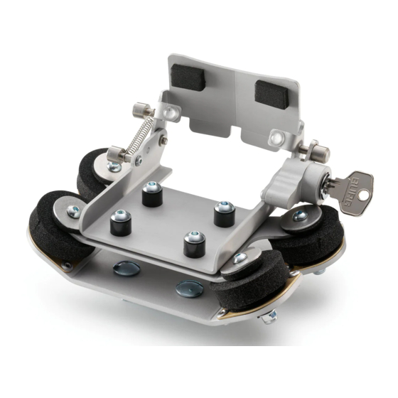
Resumen de contenidos para KTM Power Parts 60112092140
- Página 1 Information Power Parts 60112092140 06. 2008 3.211.418 *3211418* www.ktm.com...
- Página 2 Todos nuestros productos han sido desarrollados y producidos según los estándares más altos utilizando los mejores materiales disponibles. Las KTM Power Parts están probadas en competencia y garantizan un óptimo rendimiento. NO SE PUEDE HACER RESPONSABLE A LA KTM POR UN MONTAJE O UN USO INCORRECTO DE ESTE PRODUCTO.
- Página 3 Lieferumfang: 1x Aufnahmeplatte vormontiert (1) 1x Zwischenplatte (2) 1x Abschlussplatte (3) 4x Schraube M4x30 4x Schraube M5x16 4x Mutter M4 selbstsichernd 4x U-Scheibe (Alu) 4x U-Scheibe M4 4x Abstandsbuchse Kunststoff 4x Vibrationsdämpferscheibe Vorarbeiten Lesen Sie die Anleitung bitte komplett durch und beachten Sie vor allem die Hinweise bezüglich des Abschließens und Öffnen des Halters.
- Página 4 Setzen Sie die vorbereiteten Schrauben an den vier Ecken von unten durch die Schwingelemente und die Zwischenplatte und schrauben Sie diese jeweils mit einer U-Scheibe M4 (2) und einer selbstsichernden Mutter M4 (1) an (max. 3Nm). Hiermit ist der Halter einsatzbereit. Montage des Halters am Motorrad Um den Halter an ihrem Motorrad montieren zu können, lösen Sie an jeder der Klemmschellen auf der Unterseite je eine Mutter, um die Schelle z.B.
- Página 5 Demontage des GPS Gerätes Um den TOMTOM Rider 2 aus der Halterung zu nehmen, drücken Sie, wie beim Einsetzen des Gerätes (Bild (A), Seite4) mit Ihrer linken Hand von oben auf die Verschlussklappe, bis der Anschlag als Widerstand zu spüren ist. Nun lässt sich der Schlüssel leichtgängig in den Schließzylinder stecken.
-
Página 6: Mounting The Power Supply
Scope of delivery: 1x preassembled retaining plate (1) 1x intermediate plate (2) 1x end plate (3) 4x screws M4x30 4x screws M5x16 4x nuts M4, self-locking 4x U washers (Alu) 4x U washers M4 4x distance sleeves, plastic 4x vibration damper disks Preparations Please read this manual in its entirety, paying particular attention to the instruc- tions on opening and closing the holder. - Página 7 Insert the four prepared screws into the four corners from below, through the silentblock and the intermediate plate, and screw each in place with a U washer M4 (2) and a self-locking nut M4 (1) (max. 3Nm). The holder is now ready for use. Mounting the holder on the motorcycle To be able to mount the holder on your motorcycle, loosen the nut under each clamp to be able to attach the clamp to the center strut, for example.
- Página 8 Removing the GPS device To take the TOMTOM Rider 2 out of the holder, push against the locking cover from above with your left hand, as you did when inserting the device (Figure (A)) until you can feel the resistance of the stop. The key can now be easily inserted in the locking cylinder.
-
Página 9: Operazioni Preliminari
Volume della fornitura: N. 1 Piastra di alloggiamento premontata (1) N. 1 Piastra intermedia (2) N. 1 Piastra terminale (3) N. 4 Viti M4x30 N. 4 Viti M5x16 N. 4 Dadi M4 autobloccanti N. 4 Rondelle (di alluminio) N. 4 Rondelle M4 N. - Página 10 Inserire le viti precedentemente preparate ai quattro angoli posteriori dell'ele- mento oscillante e della piastra intermedia e avvitarle posizionando rispet- tivamente una rondella M4 (2) e un dado autobloccante M4 (1) (max. 3Nm). In questo modo il supporto è pronto per essere utilizzato. Montaggio del supporto sulla motocicletta Per montare il supporto sulla propria motocicletta, allentare rispettivamente un dado su ogni morsetto di bloccaggio posizionato sul lato inferiore in modo...
- Página 11 Smontaggio del dispositivo GPS Per togliere il TOMTOM Rider 2 dal supporto, premere dall'alto sul tappo come per l'inserimento del dispositivo (figura (A), pagina 4) con la mano sinistra sino a quando l'arresto non eserciterà resistenza. Ora sarà possibile inserire facilmente la chiave nel blocchetto di chiusura.
- Página 12 Contenu de la livraison : 1 plaque support prémontée (1) 1 plaque intermédiaire (2) 1 plaque terminale (3) 4 vis M4x30 4 vis M5x16 4 écrous M4 autobloquants 4 rondelles en U (alu) 4 rondelles en U M4 4 douilles entretoises en matière plastique 4 silentblocs Travaux préliminaires Prière de lire l'intégralité...
- Página 13 Mettre les vis ainsi préparées en place aux quatre coins dans les silentblocs et la plaque intermédiaire par le bas, puis les visser chacune avec une ron- delle en U M4 (2) et un écrou M4 autobloquant (1) (3Nm maxi.). Le support est ainsi prêt à...
- Página 14 Démontage de l'appareil GPS Pour retirer le TOMTOM Rider 2 de son support, appuyer, comme lors de l'introduction de l'appareil (figure A, page 4), de la main gauche sur le rabat à charnières par le haut et le presser vers le bas jusqu'à ce qu'une résistance se fasse sentir en butée.
- Página 15 Volumen de suministro: 1x placa de sujeción preensamblada (1) 1x placa intermedia (2) 1x placa terminal (3) 4x tornillo M4x30 4x tornillo M5x16 4x tuerca M4 autofrenable 4x arandela en U (aluminio) 4x arandela en U M4 4x casquillo distanciador de plástico 4x disco amortiguador de vibraciones Trabajos previos Le rogamos que lea completamente estas instrucciones y que tenga en cuenta...
- Página 16 Pase los tornillos preparados en las cuatro esquinas desde abajo a través de los elementos de amortiguación de vibraciones y la placa intermedia, y enros- que cada uno de los tornillos con una arandela en U M4 (2) y una tuerca autofrenable M4 (1) (máx.
- Página 17 Desmontaje del equipo GPS Para extraer el TOMTOM Rider 2 de la sujeción, proceda como se muestra en la figura (A) de la página 4 para colocarlo: sujete la tapa de cierre desde arriba con la mano izquierda y oprima la tapa hacia abajo hasta que aprecie la resistencia del tope.


