Fronius Smart Meter 240V-3 UL Manual De Instrucciones
Ocultar thumbs
Ver también para Smart Meter 240V-3 UL:
- Manual de instrucciones (64 páginas) ,
- Manual de instrucciones (64 páginas) ,
- Manual de instrucciones (104 páginas)
Tabla de contenido
Publicidad
Idiomas disponibles
Idiomas disponibles
Enlaces rápidos
Publicidad
Capítulos
Tabla de contenido

Manuales relacionados para Fronius Smart Meter 240V-3 UL


Resumen de contenidos para Fronius Smart Meter 240V-3 UL
- Página 1 / Perfect Charging / Perfect Welding / Solar Energy Operating Instructions Fronius Smart Meter 240V-3 UL Fronius Smart Meter 480V-3 UL System monitoring Fronius Smart Meter 600V-3 UL Manual de instrucciones Supervisión del equipo 42,0410,2289 004-10052017...
-
Página 3: Explanation Of Safety Instructions
Fronius product. These instructions will help you familiarize yourself with the product. Reading the instructions carefully will enable you to learn about the many different features your Fronius product has to offer. This will allow you to make full use of its advan- tages. -
Página 5: Tabla De Contenido
Modbus RTU............................Set Terminating Resistor ........................Set Baud Rate............................Configuration Web Interface ......................... Operation ..............................Power Status LEDs..........................Modbus Communication LEDs ......................Technical Data ............................Accuracy ............................... Measurement ............................Models and Electrical..........................Certifications ............................Environmental ............................Mechanical............................Fronius Manufacturer's Warranty...................... -
Página 7: Safety Rules
Safety rules General The device has been manufactured using state-of-the-art technology and ac- cording to recognized safety standards. If used incorrectly or misused, howev- er, it can cause injury or death to the operator or a third party damage to the device and other material assets belonging to the operat- ing company inefficient operation of the equipment All persons involved in start-up operation, maintenance and servicing for the... -
Página 8: Qualified Service Engineers
Qualified Service The servicing information contained in these operating instructions is intended Engineers only for the use of qualified service engineers. An electric shock can be fatal. Do not carry out any actions other than those described in the documentation. This also applies to qualified personnel. -
Página 9: Fcc / Rss Compliance
FCC / RSS Com- pliance This device corresponds to the limit values for a digital device of class B in accordance with Part 15 of the FCC regulations. The limit values should pro- vide adequate protection against harmful interference in homes. This device creates and uses high frequency energy and can interfere with radio com- munications when not used in accordance with the instructions. -
Página 10: Installation
Smart Meter, software must always be kept up-to-date. The update can be started via the inverter website. Set CT-Ratio and Grid Type on the web interface of the Fronius Datamanager in Set- tings - Meter - Settings (see “Configuration web interface“) Mounting The Fronius Smart meter has two mounting holes spaced 5.375 in. -
Página 11: Circuit Protection
(circuit breaker, switch or disconnect) and overcurrent protection (fuse or circuit breaker). The Fronius Smart Meter only draws 10-30 mA, so the rating of any switches, disconnects, fuses and / or circuit breakers is determined by the wire gauge, the mains voltage and the current interrupting rating required. - Página 12 Single-Phase Three-Wire (Mid-Point Neutral) Fronius Fronius Smart Meter Datama- Ground nager CT L1 WHITE CT L2 BLACK Fuses or CT L3 Breaker ≤ 20 A Shorting Load Jumper Faces Phase L1 e.g. 120 Vac (US), Source 240 Vac (AUS) Faces Neutral e.g.
- Página 13 Three-Phase Four-Wire Wye Fronius Fronius Smart Meter Datama- Ground nager CT L1 WHITE CT L2 BLACK CT L3 Fuses or Breaker ≤ 20 A Phase L1 Source Faces Phase L2 Load Faces Phase L3 Current Transformers Neutral Three-Phase Three-Wire Delta without Neutral (only 240V-3 and 480V-3)
-
Página 14: Connect Current Transformers
The current transformers connect to the six position black screw terminal block. Connect the white and black CT wires to the Fronius Smart Meter terminals marked CT L1, CT L2 and CT L3. Excess length may be trimmed from the wires if desired. Connect each CT with the white wire aligned with the white dot on the label and the black wire aligned with the black dot. -
Página 15: Connecting The Data Communication Signals
Connecting the Connect the Data Communication Terminal from the Fronius Smart Meter to the Fro- Data Communica- nius Inverter tion Signals D+ to D+ D- to D- - to - RS485 The Fronius Solar Meter outputs are electrically isolated from dangerous voltages. -
Página 16: Modbus Rtu
CTS 206-8 T517 Data (Recommended cable: Li2YCY(TP) or CAT6a) Modbus RTU The Fronius Smart Meter must be connected to the Fronius Datamanager. If only one Fro- nius Smart Meter is installed, the Modbus Address is 1. DIP Switch Up (1) value... -
Página 17: Set Baud Rate
DIP Switch 8 9600 (default) 0, Down Configuration Go to the web interface of the Fronius Datamanager in Settings - Meter - Settings Web Interface Select “Fronius Smart Meter“ Click “Settings“ Set Location of the meter, CT-Ratio and Grid Type... -
Página 18: Operation
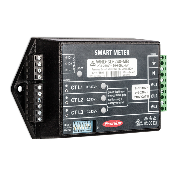
Operation Power Status The three status LEDs on the front of the Fronius Smart Meter can help indicate correct LEDs measurements and operation. The “L1”, “L2”, and “L3” on the diagrams indicate the three phases: Normal Startup The Fronius Smart Meter displays the following startup sequence whenever power is first applied. -
Página 19: Modbus Communication Leds
Meter Not Operating If none of the LEDs are illuminated, check that the correct line voltages are applied to the meter. If the voltages are correct, call customer service for assistance. Error If the meter experiences an internal error, all LEDs will light up red for 3 or more seconds. If you see this happen repeatedly, return the meter for service. -
Página 20: Technical Data
In the absence of neutral, voltages are measured with respect to ground. The Fronius Smart Meter uses the phase L1 (øA) and phase L2 (øB) connections for pow- Over-Voltage Limit: 125% of nominal Vac. Extended over-voltage operation can damage the Fronius Smart Meter and void the warranty. -
Página 21: Certifications
Black: up to 12 AWG (2.5 mm²), 300 V Fronius Manufac- Detailed warranty terms and conditions specific to your country can be found online: turer's Warranty www.fronius.com/solar/warranty To take advantage of the full warranty duration for your newly installed Fronius inverter or accumulator, register your product at: www.solarweb.com. -
Página 23: Estimado Lector
Introducción Le agradecemos su confianza y queremos felicitarle por la adquisición de este producto de Fronius de alta calidad técnica. El presente manual le ayudará a familiarizarse con el producto. Si lee detenidamente este manual, aprenderá las numerosas posibilidades que le ofrece su producto Fronius. - Página 25 Ajustar el número de baudios ....................... Configuración del interface web......................Manejo ............................... LED de estado de alimentación ......................LED de comunicación Modbus ......................Datos técnicos ............................Precisión ............................... Medición..............................Modelos y sistema eléctrico........................Certificaciones ............................Medioambiental............................. Mecánica............................... Garantía de fábrica de Fronius ......................
-
Página 27: Normativa De Seguridad
Normativa de seguridad Generalidades El equipo ha sido fabricado según el estado de la técnica y las reglas recono- cidas en referencia a la seguridad. No obstante, el manejo incorrecto o el uso inadecuado implica peligro para: La integridad física y la vida del operario o de terceras personas. El equipo y otros valores materiales de la empresa explotadora. -
Página 28: Personal Cualificado
Personal cualifi- La información de servicio en este manual de instrucciones está destinada ex- cado clusivamente a personal técnico cualificado. Las descargas eléctricas pueden ser mortales. No realizar actividades diferentes a las que se indican en la do- cumentación. Lo mismo es aplicable cuando el personal está cualificado a tal fin. -
Página 29: Fcc / Rss Compliance
FCC / RSS Com- pliance Este equipo ha sido verificado y cumple los valores límite de un equipo di- gital de la clase B según la parte 15 de las disposiciones FCC. Estos valores límite pretenden garantizar una protección adecuada frente a perturbacio- nes perjudiciales en espacios residenciales. -
Página 30: Instalación
Las actualizaciones pueden realizarse mediante la página web del inversor. Ajustar "CT-Ratio" (Ratio TC) y Grid Type (tipo de red) en el interface web del Fronius Datamanager en "Settings" - Meter" - "Settings" Ajustes - Contador - Ajustes) (ver "Configuración del interface web"). -
Página 31: Protección Del Circuito De Corriente
(fusible o disyuntor automático). El Fronius Smart Meter solo proporciona 10-30 mA, por lo que el servicio nominal de todos los interruptores, desconectores, fusibles y/o disyuntores automáticos se determina por el calibre, la tensión de red y el valor nominal requerido para interrumpir la corriente. - Página 32 ¡Si se percibe que los LED parpadean en rojo-verde-rojo-verde, significa que la tensión es excesiva para el modelo en cuestión, por lo tanto, desconectar inmediatamente el interruptor de alimentación! Tres cables monofásicos (punto medio neutro) Fronius Fronius Smart Meter Datama- Ground nager CT L1...
- Página 33 Tres cables trifásicos en estrella Fronius Fronius Smart Meter Datama- Ground nager CT L1 WHITE CT L2 BLACK CT L3 Fuses or Breaker ≤ 20 A Phase L1 Source Faces Phase L2 Load Faces Phase L3 Current Transformers Neutral Tres cables trifásicos en delta sin neutro (Sólo 240V-3 y 480V-3)
-
Página 34: Conectar Los Transformadores De Corriente
Los transformadores de corriente están conectados al bloque de bornes de tornillo negro de seis posiciones. Conectar los cables TC blanco y negro a los bornes del Fronius Smart Meter marcados como CT L1, CT L2 y CT L3. La longitud sobrante de los cables puede... -
Página 35: Conexión De Las Señales De Comunicación De Datos
Conexión de las Conectar el borne de comunicación de datos desde el Fronius Smart Meter al inversor señales de comu- Fronius nicación de datos... -
Página 36: Modbus Rtu
CTS 206-8 T517 Data (Recommended cable: Li2YCY(TP) or CAT6a) Modbus RTU El Fronius Smart Meter debe estar conectado al Fronius Datamanager. Si solo hay insta- lado un Fronius Smart Meter, la dirección de Modbus es 1. Interruptor DIP Valor arriba (1) Dirección... -
Página 37: Ajustar El Número De Baudios
Número de baudios Interruptor DIP 8 9600 (predeterminado) 0, abajo Configuración del En el interface web del Fronius Datamanager, ir a "Settings" - "Meter" - "Settings" interface web (Ajustes - Contador - Ajustes). Seleccionar "Fronius Smart Meter". Hacer clic en "Settings" (Ajustes) Ajustar Location of the meter (Ubicación del contador), CT-Ratio (Ratio TC) y Grid... -
Página 38: Manejo
Manejo LED de estado de Los tres LED de estado en frente del Fronius Smart Meter pueden ayudar a indicar las me- alimentación diciones correctas y el funcionamiento correcto. En los diagramas, "L1", "L2" y "L3" indican tres fases: Normal Startup (Puesta en servicio normal) El Fronius Smart Meter muestra la siguiente secuencia de puesta en servicio siempre que se suministre energía por primera vez. -
Página 39: Led De Comunicación Modbus
Meter Not Operating (El contador no funciona) Si ninguno de los LED está iluminado, comprobar que se están aplicando tensiones de línea correctas al contador. Si las tensiones son correctas, lla- mar al servicio de atención al cliente para recibir asistencia. Error Si se ha producido un error interno en el contador, todos los LED se iluminarán en rojo durante 3 segundos o más. -
Página 40: Datos Técnicos
Límite de sobrecorriente: 120% de la corriente nominal. Si la corriente nominal se exce- de en un 120%, no se daña el Fronius Smart Meter aunque puede que la corriente y la potencia no se midan con precisión. Sobreintensidad máxima: 4 kV según EN 61000-4-5 Consumo de corriente: La siguiente tabla muestra los valores máximos para los vol-... -
Página 41: Certificaciones
*) VA nominal es el valor máximo al 115% de la Vca nominal a 50 Hz. Se trata del mismo valor que aparece en la etiqueta frontal del Fronius Smart Meter. Rango máximo de alimentación de tensión: -20% al +15% del valor nominal (ver la ta- bla anterior). -
Página 42: Garantía De Fábrica De Fronius
Las cláusulas de garantía detalladas específicas para cada país están disponibles en In- ca de Fronius ternet: www.fronius.com/solar/warranty Para poder disfrutar de todo el período de garantía para la batería de almacenamiento o el inversor Fronius que ha instalado recientemente, rogamos que se registre en: www.solarweb.com. - Página 44 Fronius International GmbH Fronius USA LLC Solar Electronics Division 4600 Wels, Froniusplatz 1, Austria 6797 Fronius Drive, Portage, IN 46368 E-Mail: pv-sales@fronius.com E-Mail: pv-us@fronius.com http://www.fronius.com http://www.fronius-usa.com Under http://www.fronius.com/addresses you will find all addresses of our sales branches and partner firms!