
Manuales relacionados para Festo 8097522


Resumen de contenidos para Festo 8097522
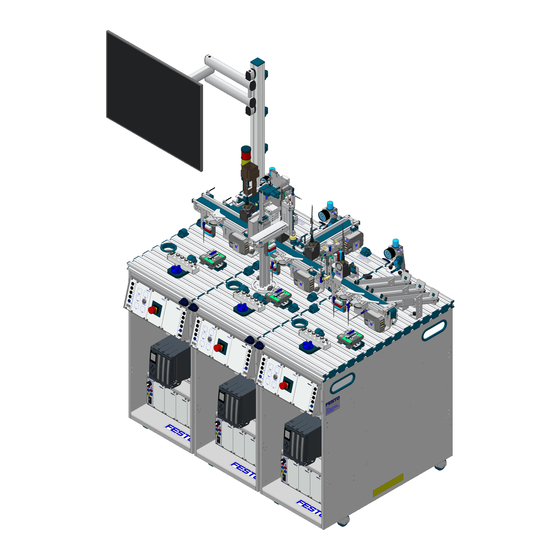
- Página 1 8097522 C Upgradekit for I4.0 ® ® Complete Systems Betriebsanleitung Operating instructions Instructions de service Notice d'utilisation...
- Página 2 08/2018 Authors: Frank Ebel, Fabian Gohlke, Christian Hartung Layout: Susanne Durz, Frank Ebel © Festo Didactic SE, Rechbergstraße 3, 73770 Denkendorf, Germany, 2018 +49 711 3467-0 www.festo-didactic.com +49 711 34754-88500 did@festo.com Weitergabe sowie Vervielfältigung dieses Dokuments, Verwertung und Mitteilung seines Inhalts verboten, soweit nicht ausdrücklich gestattet.
-
Página 3: Tabla De Contenido
Die Station Fügen Industrie 4.0 ________________________________________________________ 21 Die Station Sortieren Industrie 4.0 _____________________________________________________ 23 Funktion ___________________________________________________________________________ 24 Ablaufbeschreibung _________________________________________________________________ 24 10.1 Startvoraussetzung __________________________________________________________________ 24 10.2 Ausgangsstellung ___________________________________________________________________ 24 10.3 Richten ____________________________________________________________________________ 25 10.4 Stationen Starten ___________________________________________________________________ 25 10.5 Ablauf _____________________________________________________________________________ 25 © Festo Didactic 8097301... - Página 4 C/D ____________________________________ 29 11.4 Zusatzinformationen _________________________________________________________________ 30 11.5 Kabelverbindungen __________________________________________________________________ 31 11.6 Spannungsversorgung _______________________________________________________________ 32 11.7 SPS Programme laden _______________________________________________________________ 32 11.8 Ablauf starten ______________________________________________________________________ 32 Wartung und Pflege _________________________________________________________________ 33 Weitere Informationen und Aktualisierungen ___________________________________________ 33 © Festo Didactic 8097301...
-
Página 5: Allgemeine Voraussetzungen Zum Betreiben Der Geräte
Es dürfen keine Geräte mit Schäden oder Mängeln verwendet werden. – Schadhafte Geräte sind zu sperren und aus dem Labor- oder Unterrichtsraum zu entnehmen. – Beschädigte Verbindungsleitungen, Druckluftschläuche und Hydraulikschläuche stellen ein Sicherheitsrisiko dar und müssen aus dem Labor- oder Unterrichtsraum entfernt werden. © Festo Didactic 8097301... -
Página 6: Piktogramme
Regeln gebaut. Dennoch können bei unsachgemäßer Verwendung Gefahren für Leib und Leben des Benutzers oder Dritter und Beeinträchtigungen der Komponenten entstehen. Das Lernsystem von Festo Didactic ist ausschließlich für die Aus- und Weiterbildung im Bereich Automatisierung und Technik entwickelt und hergestellt. Das Ausbildungsunternehmen und/oder die Ausbildenden hat/haben dafür Sorge zu tragen, dass die Auszubildenden die Sicherheitsvorkehrungen, die... -
Página 7: Für Ihre Sicherheit
Stand der Technik und den anerkannten sicherheitstechnischen Regeln gebaut. Dennoch können bei ihrer Verwendung Gefahren für Leib und Leben des Benutzers oder Dritter bzw. Beeinträchtigungen an der Maschine oder an anderen Sachwerten entstehen. © Festo Didactic 8097301... -
Página 8: Arbeits- Und Sicherheitshinweise
Benutzen Sie zur Betätigung der Grenztaster ein Werkzeug, z. B. einen Schraubendreher. • Stellen Sie alle Komponenten so auf, dass das Betätigen von Schaltern und Trenneinrichtungen nicht erschwert wird. • Beachten Sie Angaben zur Platzierung der Komponenten. © Festo Didactic 8097301... - Página 9 Einige Geräte haben einen hohen Ableitstrom. Diese Geräte müssen zusätzlich mit einem Schutzleiter geerdet werden. • Wenn in den Technischen Daten nicht anders angegeben, besitzt das Gerät keine integrierte Sicherung. • Ziehen Sie beim Abbauen der Verbindungsleitungen nur an den Sicherheitssteckern, nicht an den Leitungen. © Festo Didactic 8097301...
- Página 10 Lärm durch ausströmende Druckluft kann schädlich für das Gehör sein. Reduzieren Sie den Lärm durch den Einsatz von Schalldämpfern oder tragen Sie einen Gehörschutz, falls der Lärm sich nicht vermeiden lässt. – Alle Abluftanschlüsse der Komponenten der Gerätesätze sind mit Schalldämpfern versehen. Entfernen Sie diese Schalldämpfer nicht. © Festo Didactic 8097301...
-
Página 11: Technische Daten
1050 mm x 700 mm x 1240 mm Max. Werkstückgröße MPS ® Werkstück 40 mm Verschmutzungsgrad 2, Laborumgebung Betriebstemperaturbereich 5…40 °C / 100 % Schutzart IP 20 Änderungen vorbehalten Techn. Daten PC und Accesspoint Anschluss 120-230 V AC © Festo Didactic 8097301... -
Página 12: Kontaktbelegungstabelle Station Verteilen Rel. C Mit Signalampel Im Bedienfeld
24 V B 21+22 weiß-rosa 24 V Versorgung der Eingänge weiß-grün GND A braun-rosa 0 V Versorgung der Ausgänge GND A lila 0 V Versorgung der Ausgänge braun-grün GND B 23+24 weiß-blau 0 V Versorgung der Eingänge weiß-gelb © Festo Didactic 8097301... - Página 13 Signalsäule Digital (Bedienfeld XG2) Funktion SysLink Farbe Benennung rosa Ampel grün blau Ampel gelb Ampel rot GND A braun-rosa 0 V Versorgung der Ausgänge Hinweis Bei allen Vorzugsvarianten SPS sind Kabelbrücken von NOT-AUS auf Bit 1.5 gesteckt. © Festo Didactic 8097301...
-
Página 14: Kontaktbelegungstabelle Station Fügen
GND A lila 0 V Versorgung der Ausgänge GND B 23+24 weiß-blau 0 V Versorgung der Eingänge Analog Funktion D-SUB-15 Farbe Benennung Analogeingang, Werkstückhöhe Hinweis Bei allen Vorzugsvarianten SPS sind Kabelbrücken von NOT-AUS auf Bit 1.5 gesteckt. © Festo Didactic 8097301... - Página 15 Bei XG2 laufen alle Signale über einen Busknoten, bei dem die Signale – je nach Steuerung – mit einem anderen Protokoll angesprochen werden. • Bei einer Siemens SPS: ProfiNet, • Bei einer Allen Bradley SPS: Ethernet IP • Bei einer Codesys SPS: IO-Link/Modbus © Festo Didactic 8097301...
-
Página 16: Kontaktbelegungstabelle Station Sortieren Rel. C
0 V Versorgung der Ausgänge GND A lila 0 V Versorgung der Ausgänge GND B 23+24 weiß-blau 0 V Versorgung der Eingänge Hinweis Bei allen Vorzugsvarianten SPS sind Kabelbrücken von NOT-AUS auf Bit 1.5 gesteckt. © Festo Didactic 8097301... -
Página 17: Vernetzung Des Systems
Dieser Switch ist hinter der Steuerung im Wagen der MPS ® Station Verteilen/Band. Daten-/Versorgungsleitung Siemens SIMATIC S7-1500 PROFINET Leitung 5-Port Switch RFID Schreib-/Lesekopf PC für MES System RFID Gateway mit RFID Modul PROFINET Busknoten © Festo Didactic 8097301... -
Página 18: Transport/Auspacken/Lieferumfang
Stationen werden in einer Transportbox mit Palettenboden geliefert. Die Transportbox darf ausschließlich mit geeigneten Hubwagen oder Gabelstaplern transportiert werden. Die Transportbox muss gegen Umfallen und Herunterfallen gesichert sein. Transportschäden sind unverzüglich dem Spediteur und Festo Didactic zu melden. 7.2 Auspacken ... -
Página 19: Aufbau
Mit dem Aufrüstsatz ändert sich die Anforderungen an die MPS ® Werkstücke. Sie benötigen das ® PA Werkstück Set (554301). Die MPS Werkstücke werden mit RFID Speichern (128kB) ausgestattet (8063850). Die Werkstücke sowie die RFID Speicher sind im Lieferumfang enthalten. © Festo Didactic 8097301... -
Página 20: Die Station Verteilen Industrie 4.0
Modul RFID in Verbindung mit einem Zylinder erweitert. Nachdem ein Werkstückkörper aus dem Modul Stapelmagazin ausgeschoben wurde, schreibt der RFID Schreib-/Lesekopf die Auftragsnummer, die Positionsnummer sowie Funktionen auf den RFID Tag im Werkstückkörper. Danach wird das Werkstück mithilfe des Schwenkarms zur Folgestation transportiert. © Festo Didactic 8097301... -
Página 21: Die Station Fügen Industrie 4.0
Werkstückdeckel auf die MPS Werkstückkörper zu fügen ® Hinweis Mit der Station Fügen ist es möglich, µController-Werkstückdeckel auf die MPS ® Werkstückkörper zu fügen. Hierfür benötigen Sie den Anbausatz 8064882, um vom Vakuumsauger auf einen Parallelgreifer mit Greifbacken umzurüsten. © Festo Didactic 8097301... - Página 22 Der Abstandssensor liefert sowohl ein analoges als auch ein binäres Ausgangssignal. Der binäre Schaltausgang lässt sich durch einfaches Teach-In auf die Messanforderung einstellen. Durch die Busknotenerweiterungen kann das Modul Pick&Place mit verschiedenen Bus-Protokollen – je nach Steuerung – verwendet werden. Modul Pick&Place mit verschiedenen Busknotenerweiterungen © Festo Didactic 8097301...
-
Página 23: Die Station Sortieren Industrie 4.0
Die Station wird mit dem Modul RFID erweitert. Mit dem RFID Schreib-/Lesekopf wird der RFID Tag im Werkstück gelesen und je nach Ergebnis das Werkstück ausgeschleust. Die Aufgabe der Station Sortieren Industrie 4.0 ist es • Werkstücke nach Beschaffenheit zu sortieren • Werkstücke nach Inhalt des RFID Tags zu sortieren © Festo Didactic 8097301... -
Página 24: Funktion
Werkstücke im Modul Stapelmagazin vorhanden. • Keine Werkstücke im Materialfluss der Anlage. • Alle Stationen in Ausgangsstellung und gestartet. 10.2 Ausgangsstellung • Bandmotoren der Stationen aus sowie Schwenkarm der Station Verteilen bei Folgestation • Stopper ausgefahren • Rutschen nicht voll © Festo Didactic 8097301... -
Página 25: Richten
11. Werkstück am Bandanfang erkannt 12. Bandmotor Station Fügen ein 13. Werkstückerkennung bei Bandanfang Station Fügen 14. Werk am Bandanfang der Station Fügen 15. Werkstück hält zum Lesen/Schreiben am ersten RFID Schreib-/Lesekopf bei Station Fügen 16. RFID Tag wird ausgelesen © Festo Didactic 8097301... - Página 26 45. Werkstück hält zum Lesen/Schreiben am zweiten RFID Schreib-/Lesekopf der Station Fügen 46. RFID Tag mit Werkstückstatus wird aktualisiert 47. Bandmotor Station Fügen ein 48. Werkstückerkennung bei Bandende erstes Band 49. Bandmotor Station Sortieren ein 50. Werkstückerkennung bei Bandanfang Station Sortieren 51. Bandmotor Station Fügen aus © Festo Didactic 8097301...
- Página 27 61. Zweite Weiche ausgefahren 62. Werkstück ausgeschleust 63. Zweite Weiche eingefahren 64. Bandmotor aus Farbprüfung war nicht erfolgreich 65. Umlenkung lenkt Werkstück auf letzte Rutsche 66. Werkstück ausgeschleust 67. Bandmotor aus 68. Anlage bereit für nächsten Durchlauf © Festo Didactic 8097301...
-
Página 28: Inbetriebnahme
Stationen, sind hierzu mitgeliefert. Sollte eine Verlängerung der Leitung der Verteilerleiste notwendig sein, ist dies nur von einem ausgebildeten Fachmann auszuführen. Die Steckdose hierfür muss, den Verbrauchern entsprechend, abgesichert sein. Um Probleme im Betrieb zu vermeiden, ist eine Einzelabsicherung (16 A) der Anlage dringend empfohlen. © Festo Didactic 8097301... -
Página 29: Bit Kommunikationsverbindungen Herstellen Mps ® D
Die Verbindungsleitung dient zur Kommunikation zwischen MPS Stationen mit und ohne StationLink. Als ® StationLink werden Einweg-Lichtschranken Sender und Empfänger verwendet. Die Verbindungsleitung wird anstatt der optischen Kommunikationssensoren an der MPS Station und an ® das Bedienfeld angeschlossen. © Festo Didactic 8097301... -
Página 30: Zusatzinformationen
Station mit StationLink an und stecken Sie die Sicherheitsstecker der Verbindungsleitung, wie im Bild dargestellt, in die Sicherheitsbuchsen des Bedienfelds der MPS ® Station ohne StationLink. 11.4 Zusatzinformationen Weitere Informationen, aktuelle SPS Programme für verschiedene Steuerungen und technische Dokumentationen finden Sie im Internet unter folgender Adresse: www.ip.festo-didactic.com © Festo Didactic 8097301... -
Página 31: Montage Von Profilplatte Und Bedienpult
Stecken Sie die 4 mm Sicherheitsstecker in die Buchsen des Netzgerätes. PC – SPS Verbinden Sie Ihren PC durch ein Programmierkabel mit der SPS. SPS – Busknoten Verbinden Sie die SPS durch eine Busleitung mit dem Busknoten © Festo Didactic 8097301... -
Página 32: Spannungsversorgung
Gehen Sie zum Laden der SPS Programme so vor, wie es in den Benutzerhandbüchern der von Ihnen verwendeten Programmiersoftware beschrieben ist. Aktuelle SPS Programme für verschiedene Steuerungen finden Sie im Internet unter folgender Adresse: www.festo-didactic.com > Service > ® Mechatronische Systeme > Stationen 11.8 Ablauf starten... -
Página 33: Wartung Und Pflege
Tuch oder Pinsel gereinigt werden. Hinweis Es dürfen keine aggressiven oder scheuernden Reinigungsmittel verwendet werden. 13 Weitere Informationen und Aktualisierungen Weitere Informationen, aktuelle SPS Programme für verschiedene Steuerungen und technische Dokumentationen finden Sie im Internet unter folgender Adresse: www.ip.festo-didactic.com © Festo Didactic 8097301... - Página 34 Aufrüstsatz Industrie 4.0 ® © Festo Didactic 8097301...
- Página 35 The sorting station Industry 4.0 ________________________________________________________ 55 Function ___________________________________________________________________________ 56 Sequence description _______________________________________________________________ 56 10.1 Start-up prerequisites _______________________________________________________________ 56 10.2 Initial position ______________________________________________________________________ 56 10.3 Resetting __________________________________________________________________________ 57 10.4 Starting the stations _________________________________________________________________ 57 10.5 Sequence __________________________________________________________________________ 57 © Festo Didactic 8097301...
- Página 36 Additional information _______________________________________________________________ 62 11.5 Cable connections ___________________________________________________________________ 63 11.6 Power supply _______________________________________________________________________ 64 11.7 Loading PLC programs _______________________________________________________________ 64 11.8 Starting the sequence _______________________________________________________________ 64 Maintenance and care _______________________________________________________________ 65 Further information and updates ______________________________________________________ 65 © Festo Didactic 8097301...
-
Página 37: General Prerequisites For Operating The Devices
Damaged devices must be banned from further use and removed from the laboratory or classroom. – Damaged connecting cables, pneumatic tubing and hydraulic hoses pose a safety risk and must be removed from the laboratory or classroom. © Festo Didactic 8097301... -
Página 38: Pictograms
Nevertheless, improper use can endanger the life and limb of the user or third parties as well as impair the components. The learning system from Festo Didactic has been developed and produced exclusively for basic and further training in the field of automation and technology. The training company and/or trainers must ensure that all apprentices observe the safety precautions described in this workbook. -
Página 39: For Your Safety
However, life and limb of the user or third parties may be endangered and the machine or other property may be damaged during their use. © Festo Didactic 8097301... -
Página 40: Work Instructions And Safety Precautions
Risk of injury during troubleshooting. Use a tool such as a screwdriver to actuate limit switches. • Set all components up so that activation of switches and interrupters is not made difficult. • Follow the instructions about positioning the components. © Festo Didactic 8097301... - Página 41 • The device is not equipped with an integrated fuse unless specified otherwise in the technical data. • Always pull safety plugs only when disconnecting connecting cables – never tug the cables. © Festo Didactic 8097301...
- Página 42 Noise caused by escaping compressed air may damage your hearing. Reduce noise by using silencers, or wear hearing protection if noise can’t be avoided. – All of the exhaust ports for the components included in the equipment set are equipped with silencers. Do not remove these silencers. © Festo Didactic 8097301...
-
Página 43: Technical Data
® workpiece 40 mm Degree of contamination 2. Laboratory environment Operating temperature range 5…40 °C / 100 % Degree of protection IP 20 Subject to change Tech. data PC and access point Connection 120-230 V AC © Festo Didactic 8097301... -
Página 44: Terminal Assignment Table, Distributing Station Rel. C With Signal Light In The Control Panel
24 V power supply for inputs White-green GND A Brown-pink 0 V power supply for outputs GND A Purple 0 V power supply for outputs Brown-green GND B 23+24 White-blue 0 V power supply for inputs White-yellow © Festo Didactic 8097301... - Página 45 Pink Light is green Blue Light is yellow Light is red GND A Brown-pink 0 V power supply for outputs Note: Cable jumpers are connected from emergency off to bit 1.5 for all standard PLC versions. © Festo Didactic 8097301...
-
Página 46: Terminal Assignment Table, Joining Station
0 V power supply for outputs GND B 23+24 White-blue 0 V power supply for inputs Analog Function D-SUB-15 Color Designation Analog input, workpiece height Note: Cable jumpers are connected from emergency off to bit 1.5 for all standard PLC versions. © Festo Didactic 8097301... - Página 47 In the case of XG2, all signals are transmitted via a bus node, which addresses the signals with different protocols depending on the controller. • For Siemens PLCs: ProfiNet, • For Allen Bradley PLCs: Ethernet IP • For a CoDeSys PLC: IO-Link /Modbus ® ® © Festo Didactic 8097301...
-
Página 48: Terminal Assignment Table, Sorting Station Rel. C
0 V power supply for outputs GND A Purple 0 V power supply for outputs GND B 23+24 White-blue 0 V power supply for inputs Note: Cable jumpers are connected from emergency off to bit 1.5 for all standard PLC versions. © Festo Didactic 8097301... -
Página 49: Networking The System
® distributing/conveyor station. Data/supply cable Siemens SIMATIC S7-1500 PROFINET cable 5-port switch RFID write/read head PC for MES RFID gateway with RFID module PROFINET bus node © Festo Didactic 8097301... -
Página 50: Transport, Unpacking, Delivery
When unpacking the stations, make sure that none of the built-on accessories has been damaged. Examine the stations for possible damage after unpacking. The freight forwarder and Festo Didactic must be notified immediately of any damage. 7.3 Scope of delivery Check delivered items against the delivery note and the purchase order. -
Página 51: Setup
With the upgrade kit, requirements for the MPS ® workpieces have changed. You require the MPS ® PA workpiece set (554301). MPS workpieces are equipped with RFID memories (128kB) (8063850). The workpieces and the RFID memories are included in the scope of delivery. © Festo Didactic 8097301... -
Página 52: The Distributing Station Industry 4.0
After the workpiece base has been pushed out of the stacking magazine module, the RFID read/write head writes the work order number, the item number and the functions to the RFID tag in the workpiece base. Thereafter the workpiece is transported using the swivel arm to the next station. © Festo Didactic 8097301... -
Página 53: The Joining Station Industry 4.0
Microcontroller workpiece caps can be mounted on the MPS workpiece bases with the station. ® This requires mounting kit 8064882 in order to switch over from a suction cup to a parallel gripper with gripper jaws. © Festo Didactic 8097301... - Página 54 Thanks to the bus node expansions, the pick & place module can be used with various bus protocols depending on the controller. Pick&Place module with various bus node extensions © Festo Didactic 8097301...
-
Página 55: The Sorting Station Industry 4.0
The station is extended with the RFID module. The RFID tag in the workpiece is read by the RFID read/write head and, depending on the results, the workpiece is ejected. The function of the sorting station Industry 4.0 is to: • Sort workpieces according to their characteristics • Sort workpieces according to RFID tag content © Festo Didactic 8097301... -
Página 56: Function
No workpieces in the system's material flow process. • All stations in initial position and started up. 10.2 Initial position • Conveyor motors of stations off and swivel arm of distributing station with next station • Stopper advanced • Chutes not full © Festo Didactic 8097301... -
Página 57: Resetting
13. The workpiece is detected at the start of the joining station’s conveyor belt. 14. Workpiece at the start of the joining station’s conveyor belt 15. The workpiece is stopped at the joining station’s first RFID write/read head for reading/writing. 16. The RFID tag is read. © Festo Didactic 8097301... - Página 58 48. The workpiece is detected at the end of the first conveyor. 49. Sorting station conveyor motor on 50. Workpiece is detected at the start of the sorting station’s conveyor. 51. Joining station conveyor motor off © Festo Didactic 8097301...
- Página 59 63. The second deflector is retracted. 64. Conveyor motor off Color checking unsuccessful 65. The ball return sends the workpiece to the last chute. 66. The workpiece is discharged. 67. Conveyor motor off 68. System ready for next run © Festo Didactic 8097301...
-
Página 60: Commissioning
If the cable length from the distributor block needs to be increased, this can only be carried out by appropriately trained, skilled personnel. The plug socket used must be fused appropriately for the consuming devices. In order to avoid problems during operation, individual fusing (16 A) of the system is strongly recommended. © Festo Didactic 8097301... -
Página 61: Establishing 1-Bit Communication Links Mps ® D
C stations with and without StationLink. The one-way light barrier transmitters and receivers are used as StationLink. The connecting cable is connected to the MPS C station and to the control panel instead of the optical ® communication sensors. © Festo Didactic 8097301... -
Página 62: Additional Information
MPS Station without StationLink. ® 11.4 Additional information More information, current PLC programs for various controllers and technical documentation can be found on the Internet at the following website: www.ip.festo-didactic.com © Festo Didactic 8097301... -
Página 63: Mounting The Profile Plate And The Control Console
Insert the 4 mm safety plugs into the sockets on the power pack. PC to PLC Connect your PC to the PLC via a programming cable. PLC to bus node Connect the PLC to the bus node using a bus line. © Festo Didactic 8097301... -
Página 64: Power Supply
Proceed as described in the user’s manuals for the programming software you are using in order to load the PLC programs. Current PLC programs for various controllers can be found on the Internet at the following website: www.festo-didactic.com > Services > MPS ® The Modular Production System > Stations 11.8 Starting the sequence... -
Página 65: Maintenance And Care
Note: Do not use aggressive or abrasive cleaning agents. 13 Further information and updates More information, current PLC programs for various controllers and technical documentation can be found on the Internet at the following website: www.ip.festo-didactic.com © Festo Didactic 8097301... - Página 66 Industry 4.0 upgrade kit ® © Festo Didactic 8097301...
- Página 67 Función ___________________________________________________________________________ 88 Descripción del proceso _____________________________________________________________ 88 Condiciones iniciales para la activación _________________________________________________ 88 10.2 Posición inicial______________________________________________________________________ 88 10.3 Reposición _________________________________________________________________________ 89 10.4 Puesta en marcha de las estaciones ____________________________________________________ 89 10.5 Secuencia _________________________________________________________________________ 89 © Festo Didactic 8097301...
- Página 68 Información adicional ________________________________________________________________ 94 11.5 Conexiones mediante cables __________________________________________________________ 95 11.6 Alimentación eléctrica _______________________________________________________________ 96 11.7 Cargar programas PLC _______________________________________________________________ 96 11.8 Inicio de la secuencia ________________________________________________________________ 96 Cuidados y mantenimiento ___________________________________________________________ 97 Informaciones complementarias y actualizaciones _______________________________________ 97 © Festo Didactic 8097301...
-
Página 69: Condiciones Generales Para El Uso De Los Equipos
Los equipos defectuosos deberán inhabilitarse y retirarse del laboratorio o aula. – Los cables, los tubos flexibles neumáticos y los tubos flexibles hidráulicos dañados representan un. • riesgo para la seguridad y deben retirarse del laboratorio o del aula. © Festo Didactic 8097301... -
Página 70: Pictogramas
Festo Didactic haya ocasionado dichos daños premeditadamente o con extrema negligencia. -
Página 71: Indicaciones De Seguridad
A pesar de ello, su utilización puede generar peligros que podrían afectar la integridad física o poner en peligro la vida de los usuarios o de terceros, así como también provocar daños en la máquina u otros daños materiales. © Festo Didactic 8097301... -
Página 72: Instrucciones De Seguridad Y Utilización
Para accionar los sensores de final de carrera, utilice una herramienta, por ejemplo un destornillador. • Efectúe el montaje de todos los componentes de tal manera que pueda acceder fácilmente a los interruptores y a las conexiones. • Respete las indicaciones sobre el posicionamiento de los componentes. © Festo Didactic 8097301... - Página 73 • Si no se indica lo contrario en los datos técnicos, el aparato no lleva integrado ningún fusible. • Al desconectar los cables, tire únicamente de los conectores de seguridad, nunca de los cables. © Festo Didactic 8097301...
- Página 74 Reduzca el nivel de ruidos Utilizando silenciadores, o bien tapones para los oídos si no fuese posible evitar los ruidos. – Todas las conexiones de escape de aire deberán estar provistas de silenciadores. No retire esos silenciadores. © Festo Didactic 8097301...
-
Página 75: Técnicas Generales
Grado de contaminación 2, Entorno de laboratorio Margen de temperatura de funcionamiento 5…40 °C / 100 % Grado de protección IP 20 Reservado el derecho de modificación Especificaciones técnicas del PC y Access point Conexión 120-230 V CA © Festo Didactic 8097301... -
Página 76: Tabla De Asignación De Contactos De La Estación De Distribución Rel. C Con Baliza Luminosa En El Panel De Control
0 V en las salidas Tierra A Morado alimentación de 0 V en las salidas Marrón y verde Tierra B 23+24 Blanco y azul Alimentación de 0 V en las entradas Blanco y amarillo © Festo Didactic 8097301... - Página 77 Rojo Indicador luminoso rojo Tierra A Marrón y rosa Alimentación de 0 V en las salidas Nota En todas las variantes de PLC, los cables que puentean la parada de emergencia están conectados al bit 1.5. © Festo Didactic 8097301...
-
Página 78: Tabla De Asignación De Contactos De La Estación De Unión
0 V en las entradas Analógico Función SUB-D-15 Color Denominación Entrada analógica, altura de la pieza Nota En todas las variantes de PLC, los cables que puentean la parada de emergencia están conectados al bit 1.5. © Festo Didactic 8097301... - Página 79 En XG2, todas las señales se llevan a cabo a través de un nodo de bus en el que se tratan las señales con un protocolo, en función del control. • Con PLC Siemens: ProfiNet, • Con PLC Allen Bradley: Ethernet IP • Con un PLC CoDeSys: IO-Link ® /Modbus ® © Festo Didactic 8097301...
-
Página 80: Tabla De Ocupación De Contactos De La Estación De Clasificación Rel. C
0 V en las salidas Tierra B 23+24 Blanco y azul alimentación de 0 V en las entradas Nota En todas las variantes de PLC, los cables que puentean la parada de emergencia están conectados al bit 1.5. © Festo Didactic 8097301... -
Página 81: Integración En Red Del Sistema
Estación de Distribución/Cinta MPS ® Cable de datos/alimentación Siemens SIMATIC S7-1500 Cable PROFINET Conmutador de 5 puertos Cabezal de escritura/lectura RFDI PC para sistema MES Gateway RFDI con módulo RFDI Nodo de bus PROFINET © Festo Didactic 8097301... -
Página 82: Transporte/Desembalaje/Dotación Del Suministro
La caja deberá moverse únicamente utilizando una carretilla elevadora apropiada. La caja deberá estar asegurada de tal manera que no pueda caerse. Cualquier daño ocurrido durante el transporte deberá notificarse de inmediato al transportista y a Festo Didactic. 7.2 Desembalaje ... -
Página 83: Configuración
Con el paquete de actualización se modifican los requerimientos en las piezas MPS . Es necesario ® el juego de piezas MPS PA (554301). Las piezas MPS se equipan con módulos RFID (128kB) ® (8063850). Las piezas y módulos RFID se incluyen en el suministro. © Festo Didactic 8097301... -
Página 84: Estación De Distribución Industria 4.0
Una vez expulsada una pieza del módulo de almacén apilador, el cabezal de escritura/lectura RFDI escribe el número de pedido, el número de posición y las funciones en la etiqueta RFDI de la pieza. A continuación se transporta la pieza a la estación siguiente con ayuda del brazo orientable. © Festo Didactic 8097301... -
Página 85: La Estación De Unión Industria 4.0
Con la Estación de Unión es posible unir tapas a las piezas de trabajo MPS . Para ello, se necesita ® el conjunto de montaje 8064882 para convertir el equipo de una ventosa a una pinza paralela con dedos. © Festo Didactic 8097301... - Página 86 Mediante las ampliaciones del nodo de bus, se puede utilizar el módulo pick & place con diferentes protocolos de bus, en función del sistema de mando. Módulo Pick&Place con distintas ampliaciones del nodo de bus © Festo Didactic 8097301...
-
Página 87: La Estación De Clasificación Industria 4.0
La función de la Estación de Clasificación Industria 4.0 consiste en: • clasificar piezas en función de las características, • clasificar piezas en función de la etiqueta RFDI. © Festo Didactic 8097301... -
Página 88: Función
Todas las estaciones están en posición inicial y están en marcha. 10.2 Posición inicial • Motores de las cintas de las estaciones desconectados, además del brazo giratorio de la Estación de Distribución, en la siguiente estación • Tope extendido • Plano inclinado no lleno © Festo Didactic 8097301... -
Página 89: Reposición
14. Pieza al inicio de la cinta de la Estación de Unión 15. La pieza se detiene en el primer cabezal de escritura/lectura RFDI en la Estación de Unión para la lectura/escritura 16. Se lee la etiqueta RFDI © Festo Didactic 8097301... - Página 90 49. Motor de la cinta de la Estación de Clasificación conectado 50. Detección de piezas en el inicio de la cinta de la Estación de Clasificación 51. Motor de la cinta de la Estación de Unión desconectado © Festo Didactic 8097301...
- Página 91 La comprobación de color no se ha realizado correctamente 65. Se desvía la pieza al último plano inclinado 66. Pieza a manipular expulsada 67. Motor de la cinta desconectado 68. Sistema listo para el próximo ciclo © Festo Didactic 8097301...
-
Página 92: Puesta En Marcha
Para la puesta en marcha se han creado vídeos paso por paso que se encuentran en el portal de información, disponible en http://ip.festo-didactic.com También se puede acceder escaneando el siguiente código QR. -
Página 93: Establecimiento De Las Conexiones De Comunicación De 1 Bit En Mps ® D
Como StationLink se utilizan emisores y receptores de barreras de luz unidireccionales. El cable de conexión se conecta a la MPS ® Station y al panel de control en lugar de los sensores de comunicación ópticos. © Festo Didactic 8097301... -
Página 94: Información Adicional
MPS ® Station sin StationLink. 11.4 Información adicional Puede encontrar los programas PLC actuales para las distintas unidades de control, así como documentación técnica e información adicional en la siguiente dirección de Internet: www.ip.festo-didactic.com © Festo Didactic 8097301... -
Página 95: Conexiones Mediante Cables
PC – PLC Conecte el PC al PLC mediante un cable de programación. PLC – Nodo de bus Conecte el PLC con el nodo de bus mediante un cable de bus © Festo Didactic 8097301... -
Página 96: Alimentación Eléctrica
Para cargar los programas PLC, proceda tal como se indica en el manual de instrucciones del software de programación utilizado. En la dirección Internet que se indica a continuación encontrará programas PLC actuales para diversos tipos de unidades de control: www.festo-didactic.com > Asistencia técnica> MPS ® Sistemas mecatrónicos > Estaciones 11.8 Inicio de la secuencia 1. -
Página 97: Cuidados Y Mantenimiento
No deberán utilizarse detergentes agresivos ni abrasivos. 13 Informaciones complementarias y actualizaciones Puede encontrar los programas PLC actuales para las distintas unidades de control, así como documentación técnica e información adicional en la siguiente dirección de Internet: www.ip.festo-didactic.com © Festo Didactic 8097301... - Página 98 Paquete de actualización MPS Industria 4.0 ® © Festo Didactic 8097301...
- Página 99 Le poste Tri Industrie 4.0 ____________________________________________________________ 119 Fonctionnement ___________________________________________________________________ 120 Description du cycle ________________________________________________________________ 120 10.1 Condition de démarrage _____________________________________________________________ 120 10.2 Position initiale ____________________________________________________________________ 120 10.3 Mise en référence __________________________________________________________________ 121 10.4 Démarrage des postes ______________________________________________________________ 121 10.5 Cycle _____________________________________________________________________________ 121 © Festo Didactic 8097301...
- Página 100 Raccords de câblage ________________________________________________________________ 127 11.6 Alimentation électrique _____________________________________________________________ 128 11.7 Chargement des programmes API _____________________________________________________ 128 11.8 Démarrage du cycle ________________________________________________________________ 128 Maintenance et entretien ___________________________________________________________ 129 Informations complémentaires et mises à jour _________________________________________ 129 © Festo Didactic 8097301...
-
Página 101: Exigences Générales Pour L'utilisation De L'équipement
– Les câbles de connexion, tubes pneumatiques et flexibles hydrauliques endommagés présentent un risque de sécurité et doivent être retirés du laboratoire ou de la salle de classe. © Festo Didactic 8097301... -
Página 102: Pictogrammes
être compromis. Le système de formation de Festo Didactic est exclusivement destiné à la formation initiale et continue dans le domaine de l’automatisation et de la technique. Il incombe à l’établissement de formation et/ou aux formateurs de faire respecter par les stagiaires les consignes de sécurité... -
Página 103: Pour Votre Sécurité
Son utilisation peut néanmoins mettre en danger la vie et la santé de l’utilisateur ou de tiers ainsi qu’affecter l’intégrité de la machine ou d’autres biens. © Festo Didactic 8097301... -
Página 104: Consignes De Travail Et Précautions De Sécurité
Utilisez un outil, par exemple un tournevis, pour actionner les capteurs de fin de course. • Installez les composants de telle sorte qu'ils ne gênent pas l'actionnement d'interrupteurs ni de dispositifs de sectionnement de l'alimentation. • Notez les indications concernant l'implantation des composants. © Festo Didactic 8097301... - Página 105 • Sauf indications contraires dans les caractéristiques techniques, l'appareil ne possède pas de fusible intégré. • Pour débrancher les câbles de connexion, tirez sur les fiches mâles de sécurité, pas sur les câbles. © Festo Didactic 8097301...
- Página 106 Le bruit produit par l'échappement d'air comprimé peut nuire à l'ouïe. Réduisez le bruit en utilisant des silencieux ou portez un casque anti-bruit si le bruit est inévitable. – Équipez tous les orifices d'échappement des jeux d'équipement de silencieux. Ne retirez pas ces silencieux. © Festo Didactic 8097301...
-
Página 107: Caractéristiques Techniques
2, environnement de laboratoire Plage de température de service 5…40 °C / 100 % Degré de protection IP 20 Sous réserve de modifications Données techn. sur le PC et le point d'accès Raccordement 120-230 V AC © Festo Didactic 8097301... -
Página 108: Brochage Du Poste Distribution Avec Colonne De Signalisation Sur Le Panneau De Commande
24 V B 21+22 blanc-rose Alimentation 24 V des entrées blanc-vert GND A marron-rose Alimentation 0 V des sorties GND A lilas Alimentation 0 V des sorties marron-vert GND B 23+24 blanc-bleu Alimentation 0 V des entrées blanc-jaune © Festo Didactic 8097301... - Página 109 Lampe verte bleu Lampe jaune rouge Lampe rouge GND A marron-rose Alimentation 0 V des sorties Nota Sur toutes les variantes préférentielles d'automates API, des cavaliers sont enfichés entre COUPURE D’URGENCE et le bit 1.5. © Festo Didactic 8097301...
-
Página 110: Brochage Du Poste Assemblage
23+24 blanc-bleu Alimentation 0 V des entrées Analogique Fonctionneme SUB-D-15 Couleur Désignation Entrée analogique, hauteur de pièce Nota Sur toutes les variantes préférentielles d'automates API, des cavaliers sont enfichés entre COUPURE D’URGENCE et le bit 1.5. © Festo Didactic 8097301... - Página 111 Sur XG2, tous les signaux transitent par un nœud de bus dans lequel les signaux sont traités, selon l'automate de commande, avec un autre protocole. • Pour un automate API Siemens : Profinet, • Pour un automate API Allen Bradley : Ethernet IP • Pour un API Codesys : IO-Link/Modbus © Festo Didactic 8097301...
-
Página 112: Brochage Du Poste Tri Rel. C
GND A lilas Alimentation 0 V des sorties GND B 23+24 blanc-bleu Alimentation 0 V des entrées Nota Sur toutes les variantes préférentielles d'automates API, des cavaliers sont enfichés entre COUPURE D’URGENCE et le bit 1.5. © Festo Didactic 8097301... -
Página 113: Mise En Réseau Du Système
Distribution/Convoyeur. ® Câble de données / d'alimentation Siemens SIMATIC S7-1500 Câble PROFINET Commutateur à 5 ports Plot de lecture/écriture PC pour système de MES Passerelle RFID avec module RFID Nœud de bus PROFINET © Festo Didactic 8097301... -
Página 114: Transport/Déballage/Contenu De La Livraison
La caisse de transport doit être exclusivement manutentionnée au moyen de transpalettes ou de chariots à fourche appropriés. Bloquer la caisse de transport pour qu'elle ne puisse pas se renverser ni tomber. Tout dommage dû au transport doit être immédiatement signalé au transporteur et à Festo Didactic. 7.2 Déballage ... -
Página 115: Structure
Vous devez avoir le set de pièce à usiner MPS PA (554301). Les pièces MPS sont équipées de mémoires RFID ® (128 ko) (8063850). Les pièces et les mémoires RFID sont fournies. © Festo Didactic 8097301... -
Página 116: Le Poste Distribution Industrie 4.0
Après l'extraction d'une pièce du chargeur du module Chargeur-empileur, le plot de lecture/écriture RFID inscrit le numéro de commande, le numéro de poste ainsi que les fonctions sur l'étiquette RFID de la pièce. La pièce est ensuite transportée vers le poste aval par le bras pivotant. © Festo Didactic 8097301... -
Página 117: Le Poste Assemblage Industrie 4.0
Le poste Assemblage permet de poser des couvercles de pièce à microcontrôleur sur les corps de pièce MPS . Vous avez besoin pour ce faire d'un kit de montage 8064882 pour remplacer la ® ventouse par une pince à serrage parallèle à mors (de pince). © Festo Didactic 8097301... - Página 118 être ajustée aux besoins de la mesure par simple « teach-in ». Grâce aux extensions par des nœuds de bus, le module Pick&Place peut être utilisé, selon la commande, avec divers protocoles de bus. Module Pick&Place avec divers extensions de bus © Festo Didactic 8097301...
-
Página 119: Le Poste Tri Industrie 4.0
évacue la pièce. La fonction du poste Tri Industrie 4.0 est de • de trier les pièces en fonction de leur constitution • de trier les pièces en fonction du contenu de l'étiquette RFID © Festo Didactic 8097301... -
Página 120: Fonctionnement
• Tous les postes en position initiale et démarrés. 10.2 Position initiale • Moteurs de convoyeur des postes arrêtés comme le bras pivotant du poste Distribution du poste aval • Stoppeur sorti • Goulottes pas pleines © Festo Didactic 8097301... -
Página 121: Mise En Référence
13. Détection de la pièce en début de convoyeur du poste Assemblage 14. Pièce en début de convoyeur du poste Assemblage 15. La pièce s'arrête au premier plot de lecture/écriture RFID du poste Assemblage pour lecture/écriture 16. Lecture de l'étiquette RFID © Festo Didactic 8097301... - Página 122 48. Détection de la pièce à la fin du premier convoyeur 49. Mise en marche du moteur de convoyeur du poste Tri 50. Détection de la pièce en début de convoyeur du poste Tri 51. Arrêt du moteur de convoyeur du poste Assemblage © Festo Didactic 8097301...
- Página 123 64. Moteur du convoyeur à l’arrêt Contrôle de couleur négatif 65. Le déflecteur envoie la pièce sur la dernière goulotte 66. Pièce évacuée 67. Moteur du convoyeur à l’arrêt 69. Installation prête pour le cycle suivant © Festo Didactic 8097301...
-
Página 124: Mise En Service
Pour la mise en service, des vidéos ont été créées montrant celle-ci étape par étape. Vous les trouverez dans le portail d'information à http://ip.festo-didactic.com ou vous scannez le code QR ci-après. 11.1 Mise en service électrique Il convient à... -
Página 125: Établir Des Connexions De Communication À 1 Bit Mps ® D
® utilisés sont des barrières photoélectriques à transmission, comprenant émetteur et récepteur. Le câble de liaison est raccordé au poste MPS ® et au panneau de commande, en lieu et place des capteurs de communication optiques. © Festo Didactic 8097301... -
Página 126: Informations Complémentaires
MPS sans StationLink. ® 11.4 Informations complémentaires Vous trouverez de plus amples informations, les programmes API actuels des différents automates et les documentations techniques sur Internet à l'adresse suivante : www.ip.festo-didactic.com © Festo Didactic 8097301... -
Página 127: Raccords De Câblage
4 mm aux connecteurs femelles du bloc d'alimentation. PC – API Reliez votre PC à l'API par un câble de programmation. API – Nœud de bus Reliez l'API au nœud de bus par un câble de bus © Festo Didactic 8097301... -
Página 128: Alimentation Électrique
Pour charger les programmes API, procédez comme décrit dans les manuels du logiciel de programmation que vous utilisez. Vous trouverez les programmes API actualisés des différents automates sur Internet à l'adresse suivante : www.festo-didactic.com > Service > Systèmes mécatroniques MPS > Postes ®... -
Página 129: Maintenance Et Entretien
Il est interdit d'utiliser des produits de nettoyage agressifs ou abrasifs. 13 Informations complémentaires et mises à jour Vous trouverez de plus amples informations, les programmes API actuels des différents automates et les documentations techniques sur Internet à l'adresse suivante : www.ip.festo-didactic.com © Festo Didactic 8097301... - Página 130 Kit d'extension Industrie 4.0 ® © Festo Didactic 8097301...
- Página 132 Festo Didactic SE Rechbergstraße 3 73770 Denkendorf Germany +49 711 3467-0 www.festo-didactic.com +49 711 34754-88500 did@festo.com...