
Manuales relacionados para Festo 8063910


Resumen de contenidos para Festo 8063910
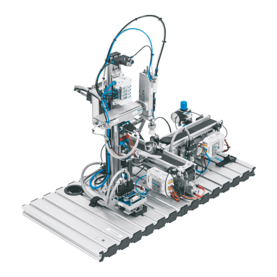
- Página 1 8063910 Joining station Stations Betriebsanleitung Operating instructions Instrucciones de utilización Notice d'utilisation Festo Didactic 8065303 de/en/es/fr 03/2020...
- Página 2 Revision level: 03/2020 Authors: Frank Ebel, Mustafa Ersoy Layout: Festo Didactic © Festo Didactic SE, Rechbergstraße 3, 73770 Denkendorf, Germany, 2020 +49 711 3467-0 www.festo-didactic.com +49 711 34754-88500 did@festo.com Originalbetriebsanleitung Weitergabe sowie Vervielfältigung dieses Dokuments, Verwertung und Mitteilung seines Inhalts verboten, soweit nicht ausdrücklich gestattet.
- Página 3 Soweit in dieser Betriebsanleitung nur von Lehrer, Schüler etc. die Rede ist, sind selbstverständlich auch Lehrerinnen, Schülerinnen etc. gemeint. Die Verwendung nur einer Geschlechtsform soll keine geschlechtsspezifische Benachteiligung sein, sondern dient nur der besseren Lesbarkeit und dem besseren Verständnis der Formulierungen. VORSICHT Diese Betriebsanleitung muss dem Anwender ständig zur Verfügung stehen.
- Página 4 Ces notices d'utilisation doivent être constamment à la disposition de l'utilisateur. Les instructions de service doivent avoir été lues avant la mise en service. Se conformer aux consignes de sécurité. Le non-respect peut entraîner de graves dommages corporels ou matériels. © Festo Didactic 8065303...
-
Página 5: Tabla De Contenido
Transport ________________________________________________________________________ 23 Auspacken _______________________________________________________________________ 23 Lieferumfang _____________________________________________________________________ 23 Aufbau __________________________________________________________________________ 24 Die Station Fügen _________________________________________________________________ 24 Das Modul Band 1 ________________________________________________________________ 26 Das Modul Band 2 ________________________________________________________________ 27 Das Modul Pick&Place _____________________________________________________________ 28 Funktion ________________________________________________________________________ 29 © Festo Didactic 8065303... - Página 6 12.4 Kabelverbindungen _______________________________________________________________ 32 12.5 Spannungsversorgung _____________________________________________________________ 33 12.6 SPS Programme laden _____________________________________________________________ 33 12.7 Ablauf starten ____________________________________________________________________ 33 Zubehör _________________________________________________________________________ 34 Wartung und Reinigung ____________________________________________________________ 35 Weitere Informationen und Aktualisierungen __________________________________________ 35 Entsorgung ______________________________________________________________________ 35 © Festo Didactic 8065303...
-
Página 7: Allgemeine Voraussetzungen Zum Betreiben Der Geräte
Es dürfen keine Geräte mit Schäden oder Mängeln verwendet werden. – Schadhafte Geräte sind zu sperren und aus dem Labor- oder Unterrichtsraum zu entfernen. – Beschädigte Verbindungsleitungen, Druckluftschläuche und Hydraulikschläuche stellen ein Sicherheitsrisiko dar und müssen aus dem Labor- oder Unterrichtsraum entfernt werden. © Festo Didactic 8065303... -
Página 8: Sicherheitshinweise Und Piktogramme
… weist auf eine möglicherweise gefährliche Situation hin, die zu mittleren und leichten Körperverletzungen oder zu schwerem Sachschaden führen kann, wenn sie nicht vermieden wird. HINWEIS … weist auf eine möglicherweise gefährliche Situation hin, die zu Sachschaden oder Funktionsverlust führen kann, wenn sie nicht vermieden wird. © Festo Didactic 8065303... -
Página 9: Piktogramme
Station Fügen 2.2 Piktogramme Warnung vor einer Gefahrenstelle Warnung vor gefährlicher elektrischer Spannung Informationen und/oder Verweise auf andere Dokumentationen © Festo Didactic 8065303... -
Página 10: Bestimmungsgemäße Verwendung
Regeln gebaut. Dennoch können bei unsachgemäßer Verwendung Gefahren für Leib und Leben des Benutzers oder Dritter und Beeinträchtigungen der Komponenten entstehen. Das Lernsystem von Festo Didactic ist ausschließlich für die Aus- und Weiterbildung im Bereich Automatisierung und Technik entwickelt und hergestellt. Das Ausbildungsunternehmen und/oder die Ausbildenden hat/haben dafür Sorge zu tragen, dass die Auszubildenden die Sicherheitsvorkehrungen, die... -
Página 11: Für Ihre Sicherheit
4 Für Ihre Sicherheit 4.1 Wichtige Hinweise Grundvoraussetzung für den sicherheitsgerechten Umgang und den störungsfreien Betrieb der Komponenten und Systeme von Festo Didactic ist die Kenntnis der grundlegenden Sicherheitshinweise und der Sicherheitsvorschriften. Diese Betriebsanleitung enthält die wichtigsten Hinweise, um die Komponenten und Systeme sicherheitsgerecht zu betreiben. -
Página 12: Verpflichtung Des Betreibers
Alle Personen, die mit Arbeiten an den Komponenten und Systemen beauftragt sind, verpflichten sich, vor Arbeitsbeginn: • das Sicherheitskapitel und die Warnhinweise in dieser Betriebsanleitung zu lesen, • die grundlegenden Vorschriften über Arbeitssicherheit und Unfallverhütung zu beachten. © Festo Didactic 8065303... -
Página 13: Arbeits- Und Sicherheitshinweise
Montieren Sie alle Komponenten fest auf die Profilplatte. • Stellen Sie sicher, dass Grenztaster nicht frontal betätigt werden. • Stellen Sie alle Komponenten so auf, dass das Betätigen von Schaltern und Trenneinrichtungen nicht erschwert wird. • Beachten Sie Angaben zur Platzierung der Komponenten. © Festo Didactic 8065303... -
Página 14: Elektrik
Beachten Sie, dass elektrische Energie in einzelnen Komponenten gespeichert sein kann. Informationen hierzu finden Sie in den Datenblättern und Betriebsanleitungen der Komponenten. – Warnung! Kondensatoren im Gerät können noch geladen sein, selbst wenn das Gerät von allen Spannungsquellen getrennt wurde. © Festo Didactic 8065303... - Página 15 VORSICHT • Versorgen Sie das System nur mit Schutzkleinspannung (SELV) oder sicherer Kleinspannung (PELV). Die Versorgung darf ausschließlich über Festo Didactic Netzteile mit Energiebegrenzung (< 100 W) oder gleichwertige Geräte erfolgen. • Das Netzgerät darf nur an einer Stromversorgung mit Schutzleiter betrieben werden.
-
Página 16: Pneumatik
Schalten Sie die Druckluft erst ein, wenn Sie alle Schlauchverbindungen hergestellt und gesichert haben. • Entkuppeln Sie keine Schläuche unter Druck. – Versuchen Sie nicht, Schläuche oder Steckverbindungen mit den Fingern oder der Hand zu verschließen. © Festo Didactic 8065303... - Página 17 Reduzieren Sie den Lärm durch den Einsatz von Schalldämpfern oder tragen Sie einen Gehörschutz, falls der Lärm sich nicht vermeiden lässt. – Alle Abluftanschlüsse der Komponenten der Gerätesätze sind mit Schalldämpfern versehen. Entfernen Sie diese Schalldämpfer nicht. © Festo Didactic 8065303...
-
Página 18: Sicherheitssteckbuchsen
Die Komponente enthält möglicherweise nicht alle der oben dargestellten Sicherheitssteckbuchsen. Im Schaltungsaufbau können durch die Verwendung verschiedener Komponenten weitere Sicherheitssteckbuchsen enthalten sein. Die angegebenen Schutzklassen und die Sicherheit werden bei Verwendung von Festo Didactic Sicherheits- Laborleitungen erreicht. © Festo Didactic 8065303... - Página 19 In Verantwortung des Betreibers kann dieser Adapter entfernt werden. Mit einem 1,5 mm Inbusschlüssel kann der Adapter gelöst werden. Die Arretierung befindet sich in der Bohrung des Adapters. Die Schraube wird rechtsdrehend gelöst. WARNUNG Gefahr durch Stromschlag! Schadhafte Sicherheits-Laborleitungen sind sofort zu sperren und aus dem Prüfbereich zu entfernen! © Festo Didactic 8065303...
-
Página 20: Technische Daten
± 10 V DC Ausgänge: Elektrischer Anschluss 24-polige IEEE-488 Buchse (SysLink) 15-poliger D-Sub Buchse Pneumatischer Anschluss Kunststoffschlauch mit 6 mm Außendurchmesser Druckluftverbrauch bei 600 kPa (Dauerzyklus) 3 l/min Maße 350 mm x 700 mm x 450 mm Änderungen vorbehalten © Festo Didactic 8065303... -
Página 21: Kontaktbelegungstabelle (Xg1)
GND A lila 0 V Versorgung der Ausgänge GND B 23+24 weiß-blau 0 V Versorgung der Eingänge Analog Funktion D-SUB-15 Farbe Benennung Analogeingang, Werkstückhöhe Bei allen Vorzugsvarianten SPS sind Kabelbrücken von NOT-AUS auf Bit 1.5 gesteckt. © Festo Didactic 8065303... -
Página 22: Kontaktbelegungstabelle (Xg2)
Bei XG2 laufen alle Signale über einen Busknoten, bei dem die Signale – je nach Steuerung – mit einem anderen Protokoll angesprochen werden. • Bei einer Siemens SPS: ProfiNet • bei einer Allen Bradley SPS: Ethernet IP • bei einer Codesys SPS: IO-Link/Modbus © Festo Didactic 8065303... -
Página 23: Transport/Auspacken/Lieferumfang
Transportieren Sie die Transportbox ausschließlich mit geeigneten Hubwagen oder Gabelstaplern. Sichern Sie die Transportbox gegen Umfallen und Herunterfallen. – Melden Sie Transportschäden unverzüglich dem Spediteur und Festo Didactic. 8.2 Auspacken Entfernen Sie beim Auspacken der Anlage oder Station vorsichtig das Füllmaterial aus der Transportbox. -
Página 24: Aufbau
Die Station kann Werkstückkörper aus dem Materialfluss entfernen bzw. in den Materialfluss einbringen. An der Weiche wird der Werkstückkörper an der Fügeposition gehalten. Durch die Busknotenerweiterungen kann das Modul Pick&Place mit verschiedenen Bus-Protokollen – je nach Steuerung – verwendet werde © Festo Didactic 8065303... - Página 25 Der binäre Schaltausgang lässt sich durch einfaches Teach-In auf die Messanforderung einstellen. Wenn das analoge Ausgangssignal des Sensors verwendet werden soll, empfiehlt es sich einen Abstand zum Messtisch von ca. 70 mm einzustellen und den Sensor mit einem Winkel von 4-7° zu befestigen. © Festo Didactic 8065303...
-
Página 26: Das Modul Band 1
Durch einen angebauten Elektromagneten (Drehmagnet) mit Vereinzeler können die Werkstücke gestoppt und vereinzelt werden. Die Endlagen des Drehmagneten werden mit induktiven Näherungsschaltern erfasst. Ein Reflex-Lichttaster mit digitalem und analogem Ausgangssignal oberhalb des Stoppers identifiziert das Werkstück und erfasst die Orientierung des Werkstücks. © Festo Didactic 8065303... -
Página 27: Das Modul Band 2
Eine zu lange Einschaltdauer kann zur Zerstörung des Getriebemotors führen. Durch den eingesetzten Motorcontroller ist Rechts-/Linkslauf, Schleichgang und Drehzahlsteuerung möglich. Der Nachweis der Werkstücke am Bandanfang und am Bandende erfolgt durch optische Näherungsschalter mit Lichtleitern. © Festo Didactic 8065303... -
Página 28: Das Modul Pick&Place
In einer weiteren Version ist an Stelle des Vakuumsaugers mit Faltenbalg ein Parallelgreifer verbaut. Der Parallelgreifer greift die Werkstücke. Ein Näherungsschalter erfasst, ob der Parallelgreifer geschlossen ist. Hierfür benötigen Sie einen Anbausatz (Bestell-Nr. 8064882), um vom Vakuumsauger auf einen Parallelgreifer mit Greifbacken umzurüsten. © Festo Didactic 8065303... -
Página 29: Funktion
• Kein Werkstück am Bandanfang von Modul Band 1 • Deckel bereit auf Modul Band 2 11.2 Ausgangsstellung • Stopper ausgefahren • Weiche eingefahren • Bandmotoren ausgeschaltet • Vakuumsauger oben • Schlitten eingefahren • Vakuum ausgeschaltet © Festo Didactic 8065303... -
Página 30: Ablauf
Falls eine Folgestation bereit ist (I6 = 1) wird das Werkstück zur Folgestation transportiert. Falls innerhalb von 300 s kein Sensorsignal erfasst wird, schaltet das Modul Band 1 automatisch ab und die Station geht auf „Störung“ (Leuchtmelder Q1 = 1). © Festo Didactic 8065303... -
Página 31: Inbetriebnahme
SPS Board mit 16 digitalen Ein- und Ausgängen • ein Netzgerät 24 V DC, 4 A, ≤ 100 W Ausgangsleistung, SELV/PELC Energiebegrenztes Netzgerät (LPS) • eine Druckluftversorgung mit 600 kPa (6 bar) • einen PC mit installierter SPS Programmiersoftware • zwei E/A-Kabel (SysLink) © Festo Didactic 8065303... -
Página 32: Montage Von Profilplatte Und Bedienpult
Buchse B durch ein SysLink Kabel mit der SysLink Buchse des Bedienpults. SPS Board – Netzgerät Stecken Sie die 4 mm Sicherheitsstecker in die Buchsen des Netzgerätes. PC – SPS Verbinden Sie Ihren PC durch ein Programmierkabel mit der SPS. © Festo Didactic 8065303... -
Página 33: Spannungsversorgung
9. Die Station startet den Ablauf. • Der Ablauf kann durch Drücken des NOT-HALT Tasters oder durch Drücken des STOP Tasters jederzeit unterbrochen werden. • Bei einer Kombination mehrerer Stationen gilt: Richten der einzelnen Stationen erfolgt entgegen dem Materialfluss. © Festo Didactic 8065303... -
Página 34: Zubehör
Siemens SIMATIC S7-313C-2DP (MPS) 567103 Siemens SIMATIC S7-314C-2PN/DP (MPS) 8034581 Siemens SIMATIC S7-315F-2PN/DP (MPS) 567104 Festo CECC-LK (MPS) 8043320 Festo CPX-CEC CODESYS 2.3 (MPS) 567274 Festo CPX-CEC CODESYS 3.5 (MPS) 8065602 Allen-Bradley CompactLogix 1769-L24ER-QB1B (MPS) 8034582 • E/A-Datenkabel mit SysLink-Steckern nach IEEE 488, 2,5 m 34031 •... -
Página 35: Wartung Und Reinigung
Station Fügen 14 Wartung und Reinigung Die Komponenten und Systeme von Festo Didactic sind weitestgehend wartungsfrei. In regelmäßigen Abständen sollten: • die Linsen der optischen Sensoren, der Faseroptiken sowie Reflektoren • die aktive Fläche der Näherungsschalter • die gesamte Komponente bzw. das System mit einem weichen, fuselfreien Tuch oder Pinsel gereinigt werden. - Página 36 Station Fügen © Festo Didactic 8065303...
- Página 37 Unpacking _______________________________________________________________________ 55 Scope of delivery _________________________________________________________________ 55 Layout __________________________________________________________________________ 56 The Joining station ________________________________________________________________ 56 The Conveyor 1 module ____________________________________________________________ 58 The Conveyor 2 module ____________________________________________________________ 59 The Pick&Place module ____________________________________________________________ 60 Function ________________________________________________________________________ 61 © Festo Didactic 8065303...
- Página 38 Cable connections ________________________________________________________________ 64 12.5 Power supply ____________________________________________________________________ 65 12.6 Loading the PLC program ___________________________________________________________ 65 12.7 Starting the sequence _____________________________________________________________ 65 Accessories ______________________________________________________________________ 66 Maintenance and care _____________________________________________________________ 67 Further information and updates ____________________________________________________ 67 Disposal ________________________________________________________________________ 67 © Festo Didactic 8065303...
-
Página 39: General Requirements For Operating The Devices
Damaged devices must be banned from further use and removed from the laboratory or classroom. – Damaged connecting cables, pneumatic tubing and hydraulic hoses represent a safety risk and must be removed from the laboratory or classroom. © Festo Didactic 8065303... -
Página 40: Safety Instructions And Pictograms
... indicates a possibly hazardous situation which may result in moderate or slight personal injury or severe property damage if not avoided. NOTICE ... indicates a possibly hazardous situation which may result in property damage or loss of function if not avoided. © Festo Didactic 8065303... -
Página 41: Pictograms
Joining station 2.2 Pictograms Warning regarding of a danger point Warning regarding dangerous electric voltage Information and/or references to other documentation © Festo Didactic 8065303... -
Página 42: Use For Intended Purpose
Festo Didactic hereby excludes any and all liability for damages suffered by trainees, the training company and/or any third parties, which occur during use of the device in situations which serve any purpose other than training and/or vocational education, unless such damages have been caused by Festo Didactic due to malicious intent or gross negligence. -
Página 43: For Your Safety
Knowledge of the basic safety instructions and safety regulations is a fundamental prerequisite for safe handling and trouble-free operation of Festo Didactic components and systems. These operating instructions include the most important instructions for safe use of the components and systems. -
Página 44: Obligations Of The Operating Company
All persons who have been entrusted to work with the components and systems undertake to complete the following steps before beginning work: • Read the chapter concerning safety and the warnings in these operating instructions. • Familiarize themselves with the basic regulations regarding work safety and accident prevention. © Festo Didactic 8065303... -
Página 45: Work And Safety Instructions
Mount all of the components securely on the profile plate. • Make sure that limit valves are not actuated from the front. • Set all components up so that it’s easy to activate the switches and interrupters. • Follow the instructions about positioning the components. © Festo Didactic 8065303... -
Página 46: Electrical Safety
Further information on this issue is available in the data sheets and operating instructions included with the components. Caution! – Capacitors inside the device may still be charged even after being disconnected from all sources of voltage. © Festo Didactic 8065303... - Página 47 • Supply the station only with safety extra-low voltage (SELV) or protective extra-low voltage (PELV): max. 24 V DC. Power must only be supplied via Festo Didactic power supply units with energy limitation (< 100 W) or equivalent devices. •...
-
Página 48: Pneumatic Safety
Do not switch on the compressed air until all the tubing connections have been established and secured. • Do not disconnect pneumatic tubing while under pressure. – Do not attempt to connect pneumatic tubing or push-in connectors with your hands or fingers. © Festo Didactic 8065303... - Página 49 Reduce noise by using pneumatic mufflers, or wear hearing protection if noise cannot be avoided. – All of the exhaust ports of the components included in the equipment sets are equipped with mufflers. Do not remove these mufflers. © Festo Didactic 8065303...
-
Página 50: Safety Sockets
The circuit design may contain additional safety sockets due to the use of different components. The specified protection class and safe use can only be assured if laboratory safety cables supplied by Festo Didactic are used. © Festo Didactic 8065303... - Página 51 1.5 mm socket head screw. The detent is located in the drilled hole of the adapter. Unscrew the screw in clockwise direction. WARNING Danger of electric shock! Damaged safety laboratory cables must be blocked immediately and removed from the laboratory area! © Festo Didactic 8065303...
-
Página 52: Technical Data
24-pole IEEE-488 socket (SysLink) 15-pole D-Sub socket Pneumatic connection Plastic tubing with 6 mm outside diameter Compressed air consumption at 600 kPa (continuous cycle) 3 l/min Dimensions 350 x 700 x 450 mm Subject to change © Festo Didactic 8065303... -
Página 53: Pin Allocation Table (Xg1)
0 V power supply for outputs GND B 23+24 White-blue 0 V power supply for inputs Analog Function D-SUB-15 Color Designation Analog input, workpiece height Cable jumpers are connected from emergency off to bit 1.5 on all PLC variants. © Festo Didactic 8065303... -
Página 54: Pin Allocation Table (Xg2)
In the case of XG2, all signals are transmitted via a bus node which addresses the signals with different protocols depending on the controller. • For Siemens PLCs: ProfiNet • For Allen Bradley PLCs: Ethernet IP • For a CoDeSys PLC: IO-Link /Modbus © Festo Didactic 8065303... -
Página 55: Transport, Unpacking, Scope Of Delivery
The crate may only be transported with a suitable pallet jack or forklift. The crate must be secured against tipping over and falling. – Report transport damage without delay to the freight forwarder and Festo Didactic. 8.2 Unpacking Carefully remove the padding material from the crate when unpacking the station. When unpacking the system or station, make sure that none of its assemblies have been damaged. -
Página 56: Layout
The station can remove workpiece bases from, or place them into the flow of materials. The workpiece base is held in the joining position at the deflector. Thanks to the bus node expansions, the Pick&Place module can be used with various protocols depending on the controller. © Festo Didactic 8065303... - Página 57 If the analogue output signal of the sensor is to be used, it is recommended to set a distance of approx. 70 mm from the measuring table and attach the sensor at an angle of 4-7°. © Festo Didactic 8065303...
-
Página 58: The Conveyor 1 Module
The workpieces can be stopped and separated by an attached electromagnet (solenoid) with separator. The end positions of the solenoid are monitored by inductive proximity sensors. The diffuse sensor with digital and analog output signal above the stopper identifies the orientation of the workpiece. © Festo Didactic 8065303... -
Página 59: The Conveyor 2 Module
The motor controller used permits clockwise/counterclockwise rotation, inching operation and speed control. The presence of workpieces at the start of the conveyor and at the end of the conveyor is verified by optical proximity switches with fiber-optic cables. © Festo Didactic 8065303... -
Página 60: The Pick&Place Module
The parallel gripper grips the workpieces. A proximity switch detects whether the parallel gripper is closed. This requires a mounting kit (order no. 8064882) in order to switch over from a suction cup to a parallel gripper with gripper jaws. © Festo Didactic 8065303... -
Página 61: Function
No workpiece at the beginning of the conveyor belt of conveyor module 1 • Cap ready on conveyor module 2 11.2 Initial position • Stopper advanced • Deflector retracted • Conveyor motors off • Suction cup up • Slide retracted • Vacuum off © Festo Didactic 8065303... -
Página 62: Sequence
If a next station is ready (I6 = 1), the workpiece is transported to the next station. If no sensor signal is received within 300 s, the motor of conveyor 1 module switches off automatically and the station goes to "Malfunction" (signal lamp Q1 = 1). © Festo Didactic 8065303... -
Página 63: Commissioning
A power supply unit: 24 V DC, 4 A, ≤ 100 W output power, SELV/PELC limited power source (LPS) • Compressed air supply: 600 kPa (6 bar) • A PC with installed PLC programming software • Two I/O cables (SysLink) © Festo Didactic 8065303... -
Página 64: Mounting The Profile Plate And The Control Console
B to the SysLink socket on the control console. PLC board to power pack Insert the 4 mm safety plugs into the sockets on the power pack. PC to PLC Connect your PC to the PLC via a programming cable. © Festo Didactic 8065303... -
Página 65: Power Supply
The sequence can be stopped by pressing the emergency stop button at any time or by pressing the STOP button after the cycle. • The following applies when several stations are combined: The individual stations are aligned in the order opposite the direction of material flow. © Festo Didactic 8065303... -
Página 66: Accessories
Siemens SIMATIC S7-314C-2PN/DP (MPS), order no.: 8034581 Siemens SIMATIC S7-315F-2PN/DP (MPS) 567104 Festo CECC-LK (MPS), order no.: 8043320 Festo CPX-CEC CODESYS 2.3 (MPS), order no.: 567274 Festo CPX-CEC CODESYS 3.5 (MPS), order no.: 8065602 Allen-Bradley CompactLogix 1769-L24ER-QB1B (MPS), order no.: 8034582 •... -
Página 67: Maintenance And Care
Joining station 14 Maintenance and care The components and systems of Festo Didactic are largely maintenance-free. The following components should be cleaned at regular intervals with a soft, lint-free cloth or brush: • The lenses on the optical sensors, the fibre optics and the reflectors •... - Página 68 Joining station © Festo Didactic 8065303...
- Página 69 Dotación del suministro ____________________________________________________________ 87 Configuración ____________________________________________________________________ 88 La Estación de Unión ______________________________________________________________ 88 Módulo cinta de transporte 1 ________________________________________________________ 90 Módulo cinta de transporte 2 ________________________________________________________ 91 El módulo Pick&Place ______________________________________________________________ 92 Función _________________________________________________________________________ 93 © Festo Didactic 8065303...
- Página 70 12.5 Alimentación de tensión ____________________________________________________________ 97 12.6 Cargar programas al PLC ___________________________________________________________ 97 12.7 Inicio del proceso _________________________________________________________________ 97 Accesorios _______________________________________________________________________ 98 Cuidados y mantenimiento _________________________________________________________ 99 Informaciones complementarias y actualizaciones _____________________________________ 99 Eliminación ______________________________________________________________________ 99 © Festo Didactic 8065303...
-
Página 71: Condiciones Generales Para El Uso De Los Equipos
Los equipos defectuosos deberán inhabilitarse y retirarse del laboratorio o aula donde se impartan las clases. – Los cables de conexión, los tubos flexibles de aire comprimido y los tubos flexibles hidráulicos dañados representan un peligro y deben retirarse del laboratorio o del aula. © Festo Didactic 8065303... -
Página 72: Pictogramas
AVISO ... indica que existe un posible peligro, que puede causar daños materiales o una pérdida de las funciones si no se adoptan las medidas necesarias para evitarlo. © Festo Didactic 8065303... -
Página 73: Pictogramas
Estación de Unión 2.2 Pictogramas Advertencia de un punto peligroso Advertencia de tensión eléctrica peligrosa Informaciones y/o referencias a otras fuentes de documentación © Festo Didactic 8065303... -
Página 74: Uso Previsto
El sistema para la enseñanza de Festo Didactic ha sido concebido exclusivamente para la formación y el perfeccionamiento profesional en materia de sistemas y técnicas de automatización industrial. La empresa... -
Página 75: Indicaciones De Seguridad
4 Indicaciones de seguridad 4.1 Observaciones importantes Para un uso seguro y sin fallas de los componentes y sistemas de Festo Didactic, es indispensable conocer las instrucciones básicas de seguridad y las normas de seguridad correspondientes. El presente manual de instrucciones contiene las informaciones más importantes para un uso correcto y seguro de los componentes y sistemas. -
Página 76: Obligaciones Asumidas Por El Usuario
Todas las personas que trabajan con los componentes y sistemas se comprometen, antes de comenzar a trabajar, a lo siguiente: • leer las indicaciones y advertencias de seguridad incluidas en el presente manual de instrucciones, • respetar las disposiciones básicas de seguridad laboral y de prevención de accidentes. © Festo Didactic 8065303... -
Página 77: Indicaciones De Seguridad Y Utilización
Asegúrese de que los interruptores de final de carrera no se accionen frontalmente. • Efectúe el montaje de todos los componentes de tal manera que pueda acceder fácilmente a los interruptores y a los seccionadores. • Respete las indicaciones sobre el posicionamiento de los componentes. © Festo Didactic 8065303... -
Página 78: Parte Eléctrica
Alimente la estación sólo con voltaje extra-bajo de seguridad (SELV) o voltaje extra- bajo de protección con aislammiento seguro (PELV): máximo 24 V DC. La energía debe ser suministrada únicamente a través de las fuentes de alimentación de Festo Didactic con limitación de energía (< 100 W) o dispositivos equivalentes. - Página 79 – transporte indebido, no se puede garantizar la ausencia de peligro al utilizar los aparatos. – En esos casos, desconecte inmediatamente la tensión. – Evite que el equipo pueda volverse a poner en funcionamiento. © Festo Didactic 8065303...
-
Página 80: Parte Neumática
Conecte el aire comprimido únicamente después de haber montado y fijado correctamente todos los racores de empalme. • No desacople tubos flexibles bajo presión. – No intente tapar tubos flexibles o conectores enchufables con los dedos o la mano. © Festo Didactic 8065303... - Página 81 Reduzca el nivel de ruido utilizando silenciadores o lleve una protección auditiva si no fuese posible evitar los ruidos. – Todas las conexiones del aire de escape de los componentes de los conjuntos de equipos están provistas de silenciadores. No retire los silenciadores. © Festo Didactic 8065303...
-
Página 82: Conectores De Seguridad
A menos que se indique lo contrario en las especificaciones técnicas, en los componentes del sistema de aprendizaje de automatización de Festo Didactic son válidos los siguientes códigos de colores para las conexiones de alimentación y de transmisión de señales. - Página 83 1,5 mm. El bloqueo se encuentra en el agujero del adaptador. El tornillo se afloja girándolo hacia la derecha. ADVERTENCIA ¡Peligro de descarga eléctrica! Los cables de seguridad defectuosos deberán inhabilitarse de inmediato y retirarse de la zona de trabajo. © Festo Didactic 8065303...
-
Página 84: Especificaciones Técnicas
Tubo flexible de material sintético de diámetro exterior de 6 mm Consumo de aire comprimido con 600 kPa (ciclo continuo) 3 l/min Dimensiones 350 mm x 700 mm x 450 mm Reservado el derecho de modificación © Festo Didactic 8065303... -
Página 85: Tabla De Asignación De Contactos (Xg1)
Alimentación de 0 V en las entradas12 Analógico Funcionamiento SUB-D-15 Color Denominación Entrada analógica, altura de la pieza En todas las variantes de PLC, los cables que puentean la parada de emergencia están conectados al bit 1.5. © Festo Didactic 8065303... -
Página 86: Tabla De Asignación De Contactos (Xg2)
En XG2, todas las señales se envían a través de un nodo de bus en el que se tratan las señales con un protocolo diferente, en función del control. • Con PLC Siemens: ProfiNet • Con PLC Allen Bradley: Ethernet IP • Con un PLC CoDeSys: IO-Link /Modbus © Festo Didactic 8065303... -
Página 87: Transporte/Desembalaje/Componentes Del Suministro
Después de retirar la estación de su caja, deberá comprobarse si ha sufrido algún daño. – Cualquier daño deberá notificarse de inmediato al transportista y a Festo Didactic. 8.3 Dotación del suministro Comprobar si el contenido de la caja corresponde a la nota de entrega y al pedido. -
Página 88: Configuración
La estación puede retirar o añadir piezas del flujo de material. En el desvío se mantiene la pieza en la posición de unión. Mediante las ampliaciones del nodo de bus, se puede utilizar el módulo Pick&Place con diferentes protocolos de bus, en función del sistema de mando. © Festo Didactic 8065303... - Página 89 Si es necesario utilizar la señal de salida analógica del sensor, se recomienda ajustar una distancia de aproximadamente 70 mm con respecto a la mesa de medición, así como fijar el sensor con un ángulo de entre 4 y 7º. © Festo Didactic 8065303...
-
Página 90: Módulo Cinta De Transporte 1
Las posiciones finales de los imanes giratorios se detectan con sensores de proximidad inductivos. Un sensor difuso con señal de salida digital y analógica por encima del tope identifica la orientación de la pieza de trabajo. © Festo Didactic 8065303... -
Página 91: Módulo Cinta De Transporte 2
Gracias al controlador de motor incorporado, es posible ejecutar giros en sentido horario y antihorario, activar la marcha lenta o el control de la velocidad. Las piezas de trabajo se detectan mediante sensores de proximidad ópticos con conductores de fibra óptica al inicio y al final de la cinta. © Festo Didactic 8065303... -
Página 92: El Módulo Pick&Place
La pinza paralela agarra la pieza. Un sensor de proximidad registra si la pinza paralela está cerrada. Para ello, se necesita el kit de fijación (nº de artículo: 8064882) para convertir la ventosa en una pinza paralela con mordazas de sujeción. © Festo Didactic 8065303... -
Página 93: Función
• Tapa preparada en el módulo de cinta 2 11.2 Posición inicial • Tope extendido • Desvío en posición retraída • Motores de las cintas desconectados • Ventosa arriba • Carro retraído • Desconexión del vacío © Festo Didactic 8065303... -
Página 94: Secuencias
(I6 = 1) se transporta la pieza hacia la estación siguiente. En caso de que no se produzca ninguna señal del sensor en 300 s, el módulo de cinta 1 se desconecta automáticamente y la estación pasa al estado "falla" (indicador luminoso Q1 = 1). © Festo Didactic 8065303... -
Página 95: Puesta A Punto
Una unidad de alimentación de 24 V DC, 4 A, ≤ 100 W potencia de salida, PELV/PELC unidad de alimentación limitada de energía (LPS) • Una alimentación de aire comprimido con 600 kPa (6 bar) • Un PC con software de programación PLC instalado • Dos cables E/S (SysLink) © Festo Didactic 8065303... -
Página 96: Montaje De La Placa Perfilada Y Del Panel De Mando
SysLink. Placa PLC - Fuente de alimentación Conecte las clavijas de seguridad de 4 mm en los conectores de la fuente de alimentación. PC – PLC Conecte el PC al PLC mediante un cable de programación. © Festo Didactic 8065303... -
Página 97: Alimentación De Tensión
STOP después del ciclo • En el caso de una combinación de varias estaciones, se aplica lo siguiente: La alineación de cada una de las estaciones se efectúa siguiendo el orden contrario al flujo del material. © Festo Didactic 8065303... -
Página 98: Accesorios
Siemens SIMATIC S7-315F-2PN/DP (MPS), nº de artículo: 567104 Festo CECC-LK (MPS), nº de artículo: 8043320 Festo CPX-CEC CODESYS 2.3 (MPS), nº de artículo: 567274 Festo CPX-CEC CODESYS 3.5 (MPS), nº de artículo: 8065602 Allen-Bradley CompactLogix 1769-L24ER-QB1B (MPS), nº de artículo: 8034582 •... -
Página 99: Cuidados Y Mantenimiento
En la dirección de internet que se indica a continuación puede consultar información complementaria y las actualizaciones de la documentación técnica de las estaciones MPS ® www.ip.festo-didactic.com 16 Eliminación Los aparatos electrónicos son reciclables y no son residuos domésticos. Se eliminan en lugares de acopio municipales. © Festo Didactic 8065303... - Página 100 Joining station © Festo Didactic 8065303...
- Página 101 Transport _______________________________________________________________________ 119 Déballage ______________________________________________________________________ 119 Fourniture ______________________________________________________________________ 119 Structure _______________________________________________________________________ 120 La station Assemblage ____________________________________________________________ 120 Le module convoyeur 1 ___________________________________________________________ 122 Le module convoyeur 2 ___________________________________________________________ 123 Le module Pick&Place ____________________________________________________________ 124 Fonction _______________________________________________________________________ 125 © Festo Didactic 8065303...
- Página 102 Alimentation électrique ___________________________________________________________ 129 12.6 Chargement des programmes API ___________________________________________________ 129 12.7 Démarrage du cycle ______________________________________________________________ 129 Accessoires _____________________________________________________________________ 130 Maintenance et entretien _________________________________________________________ 131 Informations complémentaires et mises à jour ________________________________________ 131 Mise au rebut ___________________________________________________________________ 131 © Festo Didactic 8065303...
-
Página 103: Exigences Générales Pour L'utilisation De L'équipement
Les appareils endommagés doivent être interdits d'utilisation et retirés du laboratoire ou de la salle de TP. – Les câbles électriques, tuyaux pneumatiques et hydrauliques endommagés présentent un risque pour la sécurité et doivent être retirés du laboratoire ou de la salle de TP. © Festo Didactic 8065303... -
Página 104: Consignes Des Sécurité Et Pictogrammes
à moyennes ou des dommages matériels graves si elle n'est pas évitée. AVIS … signale une situation potentiellement dangereuse qui peut causer des dommages matériels ou une perte de fonction si elle n'est pas évitée. © Festo Didactic 8065303... -
Página 105: Pictogrammes
Station Assemblage 2.2 Pictogrammes Avertissement concernant un point de danger Avertissement concernant tension électrique dangereuse Informations et/ou renvoi à d’autres documents © Festo Didactic 8065303... -
Página 106: Usage Normal
Le système didactique de Festo Didactic est exclusivement destiné à la formation initiale et à la formation continue dans le domaine de l’automatisation et de la technique. Il incombe à l’établissement de formation et/ou aux formateurs de faire respecter par les étudiants les consignes de sécurité... -
Página 107: Pour Votre Sécurité
4.1 Notes importantes La condition de base de l’utilisation en toute sécurité et du parfait fonctionnement des composants et des systèmes de Festo Didactic est une bonne connaissance des directives et consignes fondamentales de sécurité. La présente notice d'utilisation contient les informations essentielles pour utiliser le les composants et le système en toute sécurité. -
Página 108: Engagement De L'exploitant
Avant toute opération sur les composants et systèmes, le personnel s’engage à : • lire le chapitre sur la sécurité et les avertissements de la présente notice d'utilisation, • respecter les prescriptions fondamentales de sécurité au travail et de prévention des accidents. © Festo Didactic 8065303... -
Página 109: Instructions Et Consignes De Sécurité
Veillez à ce que les capteurs de fin de course ne soient jamais actionnés de face. • Installez les appareils de manière à ne pas entraver l'actionnement des interrupteurs et dispositifs de sectionnement. • Notez les indications concernant l'implantation des composants. © Festo Didactic 8065303... -
Página 110: Électrotechnique
Vous trouverez des informations à ce sujet dans les fiches techniques et notices d'utilisation des composants. – Avertissement ! – Des condensateurs intégrés à l'appareil peuvent encore être chargés même après coupure de toutes les sources de tension. © Festo Didactic 8065303... - Página 111 N'alimentez la station qu'avec une extra-basse tension de sécurité (SELV) ou une extra-basse tension de protection (PELV) : max. 24 V DC. L'alimentation électrique ne doit être fournie que par des blocs d'alimentation de Festo Didactic avec limitation d'énergie (< 100 W) ou des dispositifs équivalents.
-
Página 112: Pneumatique
N’appliquez l’air comprimé qu’après avoir branché et fixé tous les raccords union cannelés. • Ne débranchez pas de tuyaux sous pression. – N'essayez pas d'obturer un tuyau ou un connecteur avec les doigts ou la main. © Festo Didactic 8065303... - Página 113 Le bruit produit par l'échappement d'air comprimé peut nuire à l'audition. Réduisez le bruit en utilisant des silencieux ou portez un casque anti-bruit si le bruit est inévitable. – Equipez tous les raccords d'échappement de l'équipement de silencieux. Ne retirez pas ces silencieux. © Festo Didactic 8065303...
-
Página 114: Douilles De Sécurité
La conception du circuit peut contenir des douilles de sécurité supplémentaires en raison de l'utilisation de différents composants. Les classes de protection et la sécurité indiquées ne peuvent être garanties qu'en cas d'utilisation des équipements de laboratoire de sécurité de Festo Didactic. © Festo Didactic 8065303... - Página 115 Le verrou se trouve dans le trou de l'adaptateur. Desserrer la vis en tournant vers la droite. AVERTISSEMENT Risque d'électrocution ! Les câbles de laboratoire de sécurité endommagés doivent être immédiatement interdits d'utilisation et retirés de la zone de contrôle. © Festo Didactic 8065303...
-
Página 116: Caractéristiques Techniques
Connecteur femelle 15 broches Sub-D Raccordement pneumatique Tuyau en plastique de 6 mm de diamètre extérieur Consommation d'air comprimé à 600 kPa (cycle continu) 3 l/min Dimensions 350 mm x 700 mm x 450 mm Sous réserve de modifications © Festo Didactic 8065303... -
Página 117: Tableau De Brochage (Xg1)
GND B 23+24 blanc-bleu Alimentation 0 V des entrées Analogique Fonction SUB-D-15 Couleur Désignation Entrée analogique, hauteur de pièce Sur toutes les variantes préférentielles d'API, des cavaliers sont enfichés entre ARRÊT D’URGENCE et le bit 1.5. © Festo Didactic 8065303... -
Página 118: Tableau De Brochage (Xg2)
• Pour un automate API Siemens : Profinet • Pour un automate API Allen Bradley : Ethernet IP • Pour un API CoDeSys : IO-Link /Modbus © Festo Didactic 8065303... -
Página 119: Transport/Déballage/Contenu De La Livraison
Il convient de faire en sorte que la caisse ne puisse se renverser ni tomber. – Tout dommage dû au transport doit être immédiatement signalé au transporteur et à Festo Didactic. 8.2 Déballage Au déballage de la station, retirez avec précaution le matériau de calage de la caisse. Au déballage, veillez à... -
Página 120: Structure
La station est en mesure d'extraire, resp. d'introduire des corps de pièce du/dans le flux matière. Au niveau de l'aiguillage, le corps de pièce est maintenu en position d'assemblage. Grâce aux extensions par des nœuds de bus, le module Pick&Place peut être utilisé, selon la commande, avec divers protocoles de bus. © Festo Didactic 8065303... - Página 121 Si le signal de sortie analogique du détecteur vient à être utilisé, il est recommandé d'établir un écart d'env. 70 mm par rapport à la table de mesure et de fixer le détecteur à un angle de 4-7°. © Festo Didactic 8065303...
-
Página 122: Le Module Convoyeur 1
Un électro-aimant (aimant rotatif) incorporé avec aiguillage permet d'arrêter les pièces. Les positions finales de l'aimant rotatif sont détectées par des détecteurs de proximité inductifs. Un détecteur à réflexion avec signal de sortie numérique et analogique situé en amont du stoppeur identifie l'orientation de la pièce. © Festo Didactic 8065303... -
Página 123: Le Module Convoyeur 2
Le contrôleur de moteur intégré permet le transport vers la gauche ou la droite. La reconnaissance des pièces en début de convoyeur et en fin de convoyeur est assurée par des détecteurs de proximité optiques à fibres optiques. © Festo Didactic 8065303... -
Página 124: Le Module Pick&Place
La pince à serrage parallèle saisit les pièces à usiner. Un capteur de proximité détecte si la pince à serrage parallèle est fermée. Vous avez besoin pour ce faire d'un kit de montage (référence : 8064882) pour remplacer la ventouse par une pince à serrage parallèle avec mors. © Festo Didactic 8065303... -
Página 125: Fonction
Pas de pièce en début de bande du module convoyeur 1 • Couvercle déjà sur module convoyeur 2 11.2 Position initiale • Stoppeur sorti • Aiguillage rentré • Moteurs de convoyeurs désactivés • Ventouse en haut • Chariot rentré • Vide désactivé © Festo Didactic 8065303... -
Página 126: Déroulement
(I6 = 1), la pièce est transférée à la station en aval. Si aucun signal de détecteur n'est émis dans les 300 s, le convoyeur s'arrête automatiquement et la station passe en mode « dysfonctionnement » (témoin lumineux Q1 = 1). © Festo Didactic 8065303... -
Página 127: Mise En Service
24 V DC 4 A, puissance de sortie ≤ 100 W, TBTS/TBTP Bloc d'alimentation à énergie limitée (LPS) • une alimentation en air comprimé à 600 kPa (6 bar), • un PC sur lequel est installé un logiciel de programmation d’API et • deux câbles d’E/S (SysLink). © Festo Didactic 8065303... -
Página 128: Montage De La Plaque Profilée Et Du Pupitre De Commande
Carte API – Bloc d'alimentation Branchez les fiches mâles de sécurité de 4 mm dans les douilles du bloc d'alimentation. PC – API Raccordez votre PC à l'automate API à l'aide d'un câble de programmation. © Festo Didactic 8065303... -
Página 129: Alimentation Électrique
Le cycle peut être interrompu à tout moment par actionnement du bouton ARRÊT D’URGENCE ou à la fin du cycle par actionnement du bouton STOP. • Si plusieurs stations sont combinées, la mise en référence des différentes stations s'opère dans le sens opposé au flux matière. © Festo Didactic 8065303... -
Página 130: Accessoires
Siemens SIMATIC S7-313C-2DP (MPS) 567103 Siemens SIMATIC S7-314C-2PN/DP (MPS) 8034581 Siemens SIMATIC S7-315F-2PN/DP (MPS) 567104 Festo CECC-LK (MPS) 8043320 Festo CPX-CEC CODESYS 2.3 (MPS) 567274 Festo CPX-CEC CODESYS 3.5 (MPS) 8065602 Allen-Bradley CompactLogix 1769-L24ER-QB1B (MPS) 8034582 • Câble de données E/S avec connecteurs SysLink selon IEEE 488, 2,5 m, référence : 34031 •... -
Página 131: Maintenance Et Entretien
à jour que vous trouverez sur Internet à l’adresse : www.ip.festo-didactic.com 16 Mise au rebut Les appareils électroniques usagés sont des matériaux recyclables et ne doivent pas être jetés aux ordures ménagères. Ils doivent être déposés dans les centres de collecte communaux. © Festo Didactic 8065303... - Página 132 Station Assemblage © Festo Didactic 8065303...
- Página 136 Festo Didactic SE Rechbergstraße 3 73770 Denkendorf Germany +49 711 3467-0 www.festo-didactic.com +49 711 34754-88500 did@festo.com...