Publicidad
Enlaces rápidos
Motors | Automation | Energy | Transmission & Distribution | Coatings
Graphic HMI
HMI Gráfica
HMI Gráfica
CFW900-HMI
Installation, Configuration and Operation Guide
Guía de Instalación, Configuración y Operación
Guia de Instalação, Configuração e Operação
1. SAFETY INFORMATION
1.1. SAFETY WARNINGS
NOTE!
✓
Only use the CFW900-HMI on WEG CFW900 inverter series.
It is recommended to read the CFW900 user's manual before installing or operating this accessory.
This guide contains important information regarding the proper understanding and correct
operation of the HMI.
1.2. PRELIMINARY RECOMMENDATIONS
DANGER!
!
Always disconnect the general power supply before touching any electrical component connected
to the CFW900 inverter.
High voltages may still be present even after disconnecting the power supply.
Wait for at least ten minutes to ensure the complete de-energization of the inverter.
Always connect the equipment frame to the protective earth (PE) at the proper terminal.
WARNING!
!
Electronic boards have components sensitive to electrostatic discharges.
components or connectors directly. If necessary, first touch the grounded metallic frame or wear
a grounding strap.
2. GENERAL INFORMATION
2.1. ABOUT THE MANUAL
This guide provides directions for the installation, configuration and operation of the CFW900-HMI. It can be
purchased as an acessory or already included in some CFW900 inverters.
2.2. PACKAGE CONTENT OF STANDALONE HMI
Upon receiving the product, check if the package contains:
Accessory in anti-static package.
Installation, configuration and operation guide.
2.2.1. RECEIVING AND STORAGE
The CFW900-HMI when purchased as an acessory, is supplied packed in a cardboard box.
A label is affixed to the package, identical to the one affixed to the CFW900-HMI.
Check if
The identification label of the CFW900-HMI corresponds to the purchased model.
Damages occurred during transportation. If any problem is found, contact the carrier immediately.
If the CFW900-HMI is not installed soon, keep it in the package closed, and store it in a clean and dry location
with temperature between -25 ºC and 65 ºC (-13 ºF to 149ºF).
Table 1: Package dimensions in mm (in)
(Figure
A.1).
Volume [cm 3 (in 3 )]
Height H [mm (in)]
Width L [mm (in)]
Depth P [mm (in)]
Weight [kg (lb)]
150 (5.90)
80 (3.15)
70 (2.76)
62,92 (3.84)
2.3.
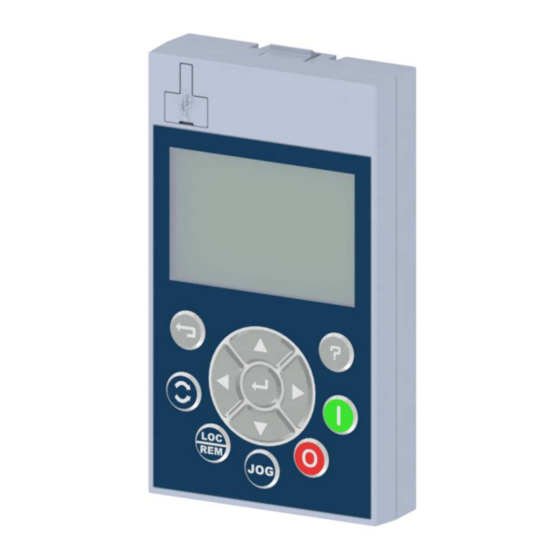
ABOUT THE CFW900-HMI
The CFW900-HMI,
Figure
A.2, enables the user to view and program the entire CFW900 with access to all the
parameters in groups (Menu). It provides USB communication.
USB connector for communication with the PC.
"Esc": Cancels programming. Goes back in the menu.
"Help": Shows help text referring to the marked content.
Increases and Decreases values. Navigation in the menu system.
Changes the main screen. Moves within values. Navigation in the menu system.
Enter soft key: Saves changes. Enters the menus.
Motor rotation direction control, if programmed for the HMI.
Selects LOCAL or REMOTE control.
JOG, if programmed for the HMI.
Stops the motor, if programmed for the HMI. Faults reset.
Starts the motor, if programmed for the HMI.
3. INSTALLATION OF CFW900-HMI
This chapter describes the electrical and mechanical installation procedures for the CFW900.
3.1. Environment Conditions
The location of the CFW900-HMI is determinant for its proper operation and for ensuring the service life of its
parts.
Avoid:
Direct exposure to sunlight, rain, excessive moisture or marine environment.
Inflammable or corrosive liquids or gases.
Excessive vibration.
Dust, metallic particles or oil mist.
Allowed Environment Conditions:
Temperature: rated conditions.
-10 ºC to 60 ºC (14 ºF to 131 ºF).
Air relative humidity: 5 % to 90 % non-condensing.
Maximum altitude: 4000 m (13123 ft) above sea level - rated conditions.
Pollution degree: 2 (according to UL508). Normally, only non-conductive pollution. Condensation
must not cause conduction through the accumulated residues.
3.2. Installing the CFW900-HMI on the CFW900
To install the CFW900-HMI follow the steps in
Figure A.3
and
Figure
A.4.
3.3. Installing the CFW900-HMI on the Panel Door
English
For panel door mounting, as shown in
Figure
A.5, use an HMI Frame Kit with the serial cable according to the
required cable size. See accessories options below.
Table 2: Accessory models
Item
Name
Description
15690771
CFW900-HMI
HMI interface (Separate)
15756246
CFW900-RHMIF
Remote HMI Frame Kit (IP66 degree of
protection)
15692985
CFW900-CCHMIR01M
Serial cable for remote HMI 1 m
15693038
CFW900-CCHMIR02M
Serial cable for remote HMI 2 m
15693040
CFW900-CCHMIR03M
Serial cable for remote HMI 3 m
15693042
CFW900-CCHMIR05M
Serial cable for remote HMI 5 m
15693044
CFW900-CCHMIR07M
Serial cable for remote HMI 7,5 m
15693045
CFW900-CCHMIR10M
Serial cable for remote HMI 10 m
Do not touch the
0,2 (0.44)
1. INSTRUCCIONES DE SEGURIDAD
1.1. AVISOS DE SEGURIDAD
¡NOTA!
✓
Solamente utilizar la CFW900-HMI en convertidores de frecuencia WEG serie CFW900
Se recomienda la lectura del manual del usuario del CFW900 antes de instalar u operar ese
accesorio CFW900-HMI
El contenido de esta guía suministra informaciones importantes para el correcto entendimiento y
el buen funcionamiento de esta HMI.
1.2. RECOMENDACIONES PRELIMINARES
¡PELIGRO!
!
Siempre desconecte la alimentación general antes de tocar cualquier componente eléctrico
asociado al convertidor CFW900.
Altas tensiones pueden estar presentes, incluso después de la desconexión de la alimentación.
Aguarde por lo menos 10 minutos para garantizar la desenergización completa del convertidor.
Siempre conecte la carcasa del equipo al tierra de protección (PE) en el punto adecuado para eso.
¡ATENCIÓN!
!
Las tarjetas electrónicas poseen componentes sensibles a descargas electroestáticas. No toque
directamente los componentes o conectores. En caso de que eso sea necesario, toque antes la
carcasa metálica puesta a tierra o utilice pulsera de puesta a tierra adecuada.
2. INFORMACIONES GENERALES
2.1. SOBRE EL MANUAL
Esta guía orienta en la instalación, configuración y operación de la CFW900-HMI. Puede adquirirse como
accesorio o ya incluido en inversores CFW900.
2.2. CONTENIDO DEL EMBALAJE
Si se compra por separado, la CFW900-HMI es suministrada embalada en caja de cartón, que contiene:
accesorio en embalaje antiestático.
Guía de Instalación, Configuración y Operación
2.2.1. RECEPCIÓN Y ALMACENAMIENTO
La CFW900-HMI es suministrada embalada en caja de cartón. En la parte externa de este embalaje existe una
etiqueta que es la misma fijada en la CFW900-HMI
Verifique si:
La etiqueta de identificación de la CFW900-HMI corresponde al modelo comprado.
Ocurrieron daños durante el transporte. En caso de que sea detectado algún problema, contacte
inmediatamente a la transportadora.
Si la CFW900-HMI no es instalada inmediatamente, manténgala dentro del embalaje cerrado y almacénela
en un lugar limpio y seco, con temperatura entre -25 °C y 65 °C (-13 ºF a 149 ºF).
Tabla 3: Dimensiones del embalaje en mm (in)
(Figura
A.1).
Volumen [cm 3 (in 3 )]
Altura H [mm (in)]
Ancho L [mm (in)]
Profundidad P [mm (in)]
150 (5.90)
80 (3.15)
70 (2.76)
62,92 (3.84)
2.3. SOBRE LA CFW900-HMI
A través de la CFW900-HMI es posible realizar la visualización y la programación de todo el CFW900 con acceso
a todos los datos a través de grupos (Menús) y comunicación USB.
Conector USB para comunicación con PC.
"Esc": Cancela programación. Vuelve al menú.
"Help": Muestra el texto de ayuda referente al contenido marcado.
Incrementa y Disminuye valores. Navegación en el sistema de menús.
Altera la pantalla principal. Se mueve dentro de valores. Navegación en el sistema de menús.
Tecla Enter: Guarda alteración. Entra en los menús.
Control del Sentido de Giro del motor, si es programado para HMI.
Selecciona comando LOCAL o REMOTO, si está habilitado.
JOG, si es programado para HMI.
Para motor, si es programado para HMI. Reset de fallas.
Gira el motor, si es programado para HMI.
3. INSTALACIÓN DE LA CFW900-HMI
Este capítulo describe los procedimientos de instalación de la CFW900.
3.1. Condiciones Ambientales
La ubicación de la CFW900-HMI es factor determinante para la obtención de un funcionamiento correcto y
para asegurar la vida útil de sus componentes
Evitar:
Exposición directa a rayos solares, lluvia, humedad excesiva o brisa marina.
Gases o líquidos explosivos o corrosivos.
Vibración excesiva.
Polvo, partículas metálicas o aceite suspendido en el aire.
Condiciones Ambientales Permitidas:
Temperatura: condiciones nominales.
-10 ºC to 60 ºC (14 ºF to 131 ºF).
Humedad relativa del aire: 5 % a 90 % sin condensación.
Altitud máxima: 4000 m (13123 ft) por encima del nivel del mar - condiciones nominales.
Grado de contaminación: 2 (conforme UL508). Normalmente, solamente contaminación no
conductiva. La condensación no debe causar conducción de los residuos acumulados.
3.2. Instalación de la CFW900-HMI en el CFW900
Para instalar la CFW900-HMI siga los pasos de la figura
Figura A.3
a la
Figura
A.4.
Español
Peso [kg (lb)]
0,2 (0.44)
Publicidad

Manuales relacionados para WEG CFW900-HMI


Resumen de contenidos para WEG CFW900-HMI
- Página 1 Si la CFW900-HMI no es instalada inmediatamente, manténgala dentro del embalaje cerrado y almacénela If the CFW900-HMI is not installed soon, keep it in the package closed, and store it in a clean and dry location en un lugar limpio y seco, con temperatura entre -25 °C y 65 °C (-13 ºF a 149 ºF).
- Página 2 CFW900. 2.2. CONTEÚDO DA EMBALAGEM DA HMI AVULSA Se a HMI CFW900-HMI foi comprada de forma avulsa, ao receber o produto, verificar se a embalagem contém: Acessório em embalagem anti-estática. Guia de instalação, configuração e operação.