Publicidad
Idiomas disponibles
Idiomas disponibles
Enlaces rápidos
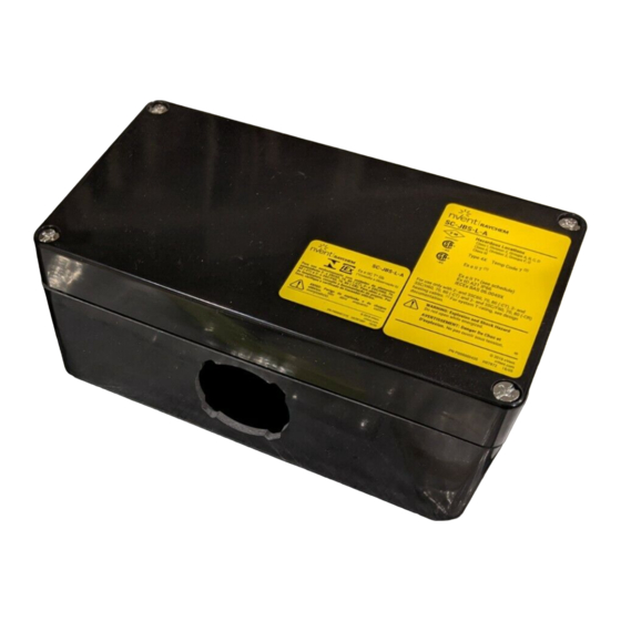
SC-JBE-L-A
End termination with junction box installation instructions
APPROVALS
Hazardous Locations
Class I, Div. 2, Groups A, B, C, D
Class II, Div. 2, Groups F, G
Class III
IEx 09.0008X
Ex eb IIC T* Gb
IECEx
IECEx BAS 06.0049X
Ex e II T* (see schedule)
hEx tD A21 IP66
KIT CONTENTS
Item Qty
Description
A
1
Stand assembly
B
1
Grommet plug
C
1
Cable lubricant
D
4
Tape strips
E
1
Coil Kester
®
48 core LF solder for nickel
F
10
Thomas & Betts splices, spares included
G
1
Junction box
H
1
Lid
I
1
Spanner
J
1
Strain relief
WARNING:
This component is an electrical device that must be installed
correctly to ensure proper operation and to prevent shock or
fire. Read these important warnings and carefully follow all of
the installation instructions.
• To minimize the danger of fire from sustained electrical
arcing if the heating cable is damaged or improperly
installed, and to comply with the requirements of nVent,
agency certifications, and national electrical codes,
ground-fault equipment protection must be used. Arcing
may not be stopped by conventional circuit breakers.
• Be sure all power sources are de-energized before
opening box.
• Keep components and heating cable ends dry before and
during installation.
(1)
Ex e II T
(1)
for T-Rating, see design
documentation
• Component approvals and performance are based on the
use of nVent-specified parts only. Do not use substitute
parts or vinyl electrical tape.
• Soldering tools or torches can cause fire or explosion
in hazardous areas. Be sure there are no flammable
materials or vapors in the area before using these tools.
• Damaged conductors can overheat or short. Do not
break conductor wire strands when scoring the jacket
or removing insulation.
• Use only fire-resistant insulation materials, such as
fiberglass wrap or flame-retardant foam.
• Wrap exposed conductors with supplied tape strips to
prevent shorts.
DESCRIPTION
The nVent RAYCHEM SC-JBE-L-A is a NEMA 4X-rated end
termination kit designed for use with RAYCHEM 2 and 3SC60, 70, 80
(-CT), 2 and 3SC/H60, 70, 80 (-CT) and 2 and 3SC/F60, 70, 80 (-CR)
series heating cables in hazardous locations.
This kit may be installed at temperatures as low as –40°F (–40°C).
For easier installation, store above freezing until just
before installation.
For technical support, call nVent at (800) 545-6258.
TOOLS REQUIRED
• Diagonal cutters
• Wire strippers
• Solder tool or torch (with small tip)
• Thomas & Betts TBM5S crimp tool (P/N P000000585) or WT2000
crimp tool (P/N 273435-000) or equivalent. Crimp tools can be
ordered from nVent.
ADDITIONAL MATERIALS REQUIRED
• Pipe straps (2)
• Glass cloth tape:
– GT-66 for installation temperature above 40°F (4°C)
– GS-54 for installation temperature above –40°F (–40°C)
OPTIONAL MATERIALS
• Recommended conduit drain:
JB-DRAIN-PLUG-3/4IN (P/N 278621-000)
• Pipe adapter to increase stand height:
SC-JB-PIPE-ADAPTER (P/N P000000648)
A
B
C
D
E
F
HEALTH HAZARD: Hot solder can burn eyes and skin.
Fumes during soldering are irritating to eyes and may cause
headache and respiratory system irritation or damage.
Prolonged or repeated exposure to rosin flux fumes during
soldering may result in allergic reaction in a sensitive person,
resulting in asthma symptoms. Consult MSDS VEN 0043 for
further information.
CHEMTREC 24-hour emergency telephone: (800) 424-9300
Non-emergency health and safety information:
(800) 545-6258
• Slotted screwdriver
• Utility knife
J
I
H
G
CAUTION:
Publicidad

Manuales relacionados para nVent RAYCHEM SC-JBE-L-A


Resumen de contenidos para nVent RAYCHEM SC-JBE-L-A
- Página 1 End termination with junction box installation instructions DESCRIPTION The nVent RAYCHEM SC-JBE-L-A is a NEMA 4X-rated end termination kit designed for use with RAYCHEM 2 and 3SC60, 70, 80 (-CT), 2 and 3SC/H60, 70, 80 (-CT) and 2 and 3SC/F60, 70, 80 (-CR) series heating cables in hazardous locations.
- Página 2 Heating cable types Heating Cable Construction 2 and 3SC60, 70 and 80 (-CT) 2 and 3SC/H60, 70 and 80 (-CT) 2 and 3SC/F60, 70 and 80 (-CR) Outer jacket Outer jacket Tinned-copper braid Tinned-copper braid Inner jacket Inner jacket Conductor insulation Conductor insulation Fiberglass braid (2SC, 2SC/H only) Fiberglass braid (3SC, 3SC/H only)
- Página 3 • Lightly score inner jacket around and • Remove 3/4-inch (20 mm) insulation and down as shown. fiberglass braid from end of each conductor. • Peel off inner jacket. 3SC heating cable shown. 5 in. (127 mm) 3/4 in. (20 mm) Fiberglass braid (only for SC, SC/H) •...
- Página 4 • Place junction box onto • Remove box nut. stand. Align key-ways in • Install grommet box hole with alignment plug in unused feature on stand. opening. • Put box nut back onto stand. • Tighten box nut with spanner. O-ring •...
- Página 5 WARNING: Fire and Health Hazard. Soldering tools or minitorches can cause fire or explosion in hazardous areas. Be sure there are no flammable materials or vapors in the area before using these tools. Follow all site safety guidelines when working in hazardous areas. Refer to solder material safety data sheet packaged with kit.
- Página 6 • Install lid. • Apply insulation and cladding. • Weather-seal stand entry. • Install electric heat-tracing labels on insulation cladding. • Leave these installation instructions with the end user for future reference. Weather seal 6 | nVent.com/RAYCHEM...
- Página 7 Terminação final com caixa de ligação instruções de instalação DESCRIÇÃO O nVent RAYCHEM SC-JBE-L-A é um kit de terminação final com classificação NEMA 4X destinado às séries de unidades de elementos aquecedores nVent RAYCHEM 2 e 3SC60, 70, 80 (-CT), 2 e 3SC/H60, 70, 80 (-CT) e 2 e 3SC/F60, 70, 80 (-CR) em localizações perigosas.
- Página 8 Tipos de unidade de elemento aquecedor Estrutura da unidade de elemento aquecedor 2 e 3SC60, 70 e 80 (-CT) 2 e 3SC/H60, 70 e 80 (-CT) 2 e 3SC/F60, 70 e 80 (-CR) Capa externa Capa externa Blindagem de cobre estanhado Blindagem de cobre estanhado Capa interna Capa interna Isolamento do condutor Isolamento do condutor...
- Página 9 • Corte ligeiramente ao redor da capa • Remova 20 mm (3/4 pol.) do isolamento e da interna e longitudinalmente como blindagem de fibra de vidro na ponta de cada mostrado. condutor. • Retire a capa interna. Unidade de elemento aquecedor 3SC mostrada na figura.
- Página 10 • Coloque a caixa de ligação no • Remova a porca da suporte. Alinhe as chavetas no caixa. furo da caixa ao dispositivo de • Instale tampão alinhamento no suporte. isolante na abertura • Coloque a porca da caixa não utilizada. novamente no suporte.
- Página 11 AVISO: Perigo de incêndio e risco para a saúde. As ferramentas de solda ou os minimaçaricos podem causar incêndio ou explosão em áreas de risco. Antes de usar essas ferramentas, verifique se não há vapores ou materiais inflamáveis na área. Siga todas as diretrizes de segurança do local ao trabalhar em áreas de risco.
- Página 12 • Instale a tampa. • Aplique o isolamento e o revestimento. • Vede hermeticamente a entrada do suporte. • Instale etiquetas de traceamento térmico elétrico no revestimento de isolamento. • Essas instruções de instalação devem permanecer com o usuário final para referência futura. Vedação hermética 12 | nVent.com/RAYCHEM...
-
Página 13: Descripción
Terminación de extremo con caja de empalmes Instrucciones de instalación DESCRIPCIÓN El nVent RAYCHEM SC-JBE-L-A es un kit de conexión de terminación de extremos con calificación NEMA 4X diseñado para su uso con cables calefactores RAYCHEM serie 2 y 3SC60, 70, 80 (-CT), 2 y 3SC/ H60, 70, 80 (-CT) y 2 y 3SC/F60, 70, 80 (-CR) en lugares peligrosos. - Página 14 Tipos de cables calefactores Construcción del cable calefactor 2 y 3SC60, 70 y 80 (-CT) 2 y 3SC/H60, 70 y 80 (-CT) 2 y 3SC/F60, 70 y 80 (-CR) Chaqueta exterior Chaqueta exterior Malla de cobre estañado Malla de cobre estañado Chaqueta interior Chaqueta interior Aislamiento del conductor...
- Página 15 • Corte ligeramente la funda interior Retire 20 mm (3/4 pulgadas) de aislamiento • alrededor y a lo largo como se indica. y de malla de fibra de vidrio del extremo de cada conductor. • Pele la chaqueta interior. Se muestra el cable calefactor 3SC. 127 mm (5 pulg.) 20 mm...
- Página 16 • Coloque la caja de conexiones • Retire la tuerca de eléctricas sobre el soporte. Alinee las caja. ranuras del orificio de la caja con la • Instale tapones indicación de alineación del soporte. de ojales en las • Vuelva a colocar la tuerca aberturas no de caja en el soporte.
- Página 17 ADVERTENCIA: Riesgo de incendio y para la salud. Las herramientas o sopletes de soldadura pueden provocar incendio o explosión en zonas peligrosas. Cerciórese de la ausencia de materiales o vapores inflamables en el lugar antes de utilizar dichas herramientas. Siga todas las directrices de seguridad del lugar cuando trabaje en zonas peligrosas.
- Página 18 • Instale la tapa. • Aplique el aislamiento y el revestimiento. • Impermeabilice la entrada del soporte. • Aplique etiquetas de traza eléctrica en el revestimiento aislante. • Deje al usuario final estas instrucciones de instalación para su consulta futura. Protección contra la intemperie...