Publicidad
Idiomas disponibles
Idiomas disponibles
Enlaces rápidos
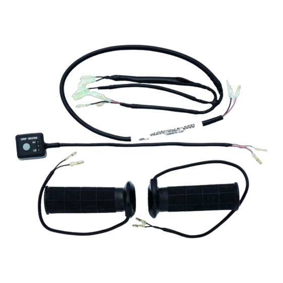
GRIP HEATER
Description:
Applications:
UB125L M3-
Ref.
Contents
①
②
③
④
⑤
⑥
⑦
⑧
⑨
⑩
①
⑤
I N S T A L L A T I O N I N S T R U C T I O N S
Description
Grip Heater Lead Wire
Grip Heater Switch
Screw
Cushion
Grip Heater (R)
Grip Heater (L)
Bolt
Switch Bracket
Clamp
Installation Instructions
②
⑥
⑨
⑩
Part Number : 57100-2781*
Installation Time : 1.2 H
③
⑦
GENUINE SUZUKI ACCESSORIES
1
/20
QTY
1
1
2
1
1
1
2
1
1
1
④
⑧
99021-27L30
D
Publicidad
Capítulos

Manuales relacionados para Suzuki 57100-2781 Serie


Resumen de contenidos para Suzuki 57100-2781 Serie
- Página 1 Grip Heater Switch ② Screw ③ Cushion ④ Grip Heater (R) ⑤ Grip Heater (L) ⑥ Bolt ⑦ Switch Bracket ⑧ Clamp ⑨ Installation Instructions ⑩ ① ② ③ ④ ⑤ ⑥ ⑦ ⑧ ⑨ ⑩ GENUINE SUZUKI ACCESSORIES 99021-27L30...
- Página 2 Open end wrench (14 mm) Socket (14 mm) Ratchet handle Cutter Rasp Torque wrench Items Ref. Description Provided (1) ECSTAR SUPER by the GREASE (A) or equivalent Customer [Recommended : 99000-25480] Grip cement [Recommended : THREE BOND 1530P] Degreasing Agent GENUINE SUZUKI ACCESSORIES...
- Página 3 7. Use care not to cause any damage to the body of the vehicle during installation of the accessory. Be sure to refer to the UB125L service manual, when removing or installing STD parts. * STD parts = Component parts of SUZUKI motorcycle GENUINE SUZUKI ACCESSORIES...
- Página 4 1. Remove the R/L mirror (A), upper handle cover (B), front handle cover (C) and rear handle cover (D). Installation of Grip Heater (R) 1. Remove the balancer screw and remove the handlebar balancer. Handlebar balancer Balancer screw GENUINE SUZUKI ACCESSORIES...
- Página 5 Don't remove the throttle cable No.1 and No.2. with a pliers or other tools forcibly. Throttle grip I t m a y c a u s e i m p r o p e r Screw operation of the throttle. GENUINE SUZUKI ACCESSORIES...
- Página 6 Screw : 1.5N . m (0.15 kgf-m, 1.00 lbf-ft) After tightening, check that the throttle case doesn’ t rattle. GENUINE SUZUKI ACCESSORIES...
- Página 7 Adjuster 2.0 - 4.0 mm play. 3) Tighten the lock-nut. 4) Install the boot. Boot Lock-nut WARNING Check that there isn't any catch during opening and closing the throttle. 2.0 〜 4.0 mm ⑤ GENUINE SUZUKI ACCESSORIES...
- Página 8 Use the driver with care s o a s n o t t o s c r a t c h t h e surface of the handlebar. Left handle grip will not be reused. GENUINE SUZUKI ACCESSORIES...
- Página 9 5. Apply grip cement to the han- Grip cement dlebar surface. [Recommended: THREE BOND 1530P] In case that bond is attached to the end surface of the handlebar, wipe off it with a waste cloth completely be- Handlebar fore drying. GENUINE SUZUKI ACCESSORIES...
- Página 10 At this time, do not twist forcibly the heater wire with a screwdriver or such similar tool, the heater wire inside the grip heater may be cut off. GENUINE SUZUKI ACCESSORIES...
- Página 11 ⑧ 1. Install the Grip Heater Switch ② to the Switch Bracket ⑧ with the Screws ③ as shown and tighten it to the specified torque. Screw : 0.4N . m ② (0.04 kgf-m, 0.3 lbf-ft) ③ GENUINE SUZUKI ACCESSORIES...
- Página 12 Wire ① as shown and connect it to the motorcycle coupler. 2. Insert the clamp of the Grip Heater Lead Wire ① in the left rear hole of the bracket in front of the handlebar. Motorcycle harness GENUINE SUZUKI ACCESSORIES...
- Página 13 25mm 〜 35mm Reinstall the handle cover so that it isn't in contact with the Grip Heater (R) ⑤ lead wire. Grip heater (R) ⑤ lead wire White tape Handle switch (R) lead wire GENUINE SUZUKI ACCESSORIES...
- Página 14 Grip Heater Switch ② to the Grip Heater Lead Wire ① as shown. Grip heater (R) ⑤ Grip heater (L) ⑥ ① Grip heater Switch ② White/ White White/ Yellow Black White/ Yellow Grip heater lead wire ① GENUINE SUZUKI ACCESSORIES...
- Página 15 ・ Face the button part of the motorcycle clamp toward the direction shown in the cross section. Left Right Motorcycle Clamp Clamp ⑨ Motorcycle Clamp Clamp ⑨ Motorcycle Clamp Front Front Front Front Clamp ⑨ Motorcycle Clamp GENUINE SUZUKI ACCESSORIES...
- Página 16 3 . Fix "d", "e", "f" and "g" with the Clamp ⑨ to the handlebar. 3. Reinstall the motorcycle parts in the reverse order of removal. Be careful that the lead wires aren’t pinched, and install the front handle cover and rear handle cover. GENUINE SUZUKI ACCESSORIES...
- Página 17 ・ C h e c k t h a t t h e G r i p H e a t e r S w i t c h ② l e a d wire isn't contact with the rear brake lever. GENUINE SUZUKI ACCESSORIES...
- Página 18 Grip heater warms right and left Grip heater switch grips when the grip heater switch is turned on with the engine running. Switch The grip heater switch will be turned off when the ignition switch is turned off. GENUINE SUZUKI ACCESSORIES...
- Página 19 ・ Pushing the switch will not turn on the grip heater when the engine speed is low. Increase the engine speed and push the switch again to turn on the grip heater. GENUINE SUZUKI ACCESSORIES...
- Página 20 20 /20 When the grip heater does not operate normally, check the following items, and consult your SUZUKI Dealer from whom you bought the product. ・ Grip heater does not operate. Or it can not be adjusted. 1. Is the grip heater switch indicator blinking? 2.
-
Página 21: Tabla De Contenido
Interrupteur du chauffe-poignée ② ③ Coussinet ④ Poignée chauffante (D) ⑤ Poignée chauffante (G) ⑥ Boulon ⑦ Support de l’interrupteur ⑧ Attache ⑨ Instructions d'installation ⑩ ① ② ③ ④ ⑤ ⑥ ⑦ ⑧ ⑨ ⑩ GENUINE SUZUKI ACCESSORIES 99021-27L30... - Página 22 Clé plate (14 mm) Douille (14 mm) Clé à cliquet Cutter Râpe Clé dynamométrique Pièces Réf. Description fournies (1) ECSTAR SUPER GREASE (A) ou équivalent le client Graisse recommandée 99000-25480] Colle pour poignée [ Colle recommandée THREE BOND 1530P] Dégraissant GENUINE SUZUKI ACCESSORIES...
- Página 23 7. Éviter d’endommager le véhicule pendant l’installation de l’acces- soire. Reportez-vous au manuel d’entretien de la UB125L lors de la dépose ou de l’installation de pièces STD. * Pièces STD = Composants de ma moto SUZUKI GENUINE SUZUKI ACCESSORIES...
- Página 24 (C) et le cache de la poignée arrière (D). Installation de la poignée chauf- fante (D) 1. Retirez la vis de balancier et retirez le balancier du guidon. Masselotte de guidon Vis du balancier GENUINE SUZUKI ACCESSORIES...
- Página 25 La poignée des gaz ne sera pas réutilisée. Poignée droite Ne retirez pas le câble des gaz N° 1 et N° 2 avec une pince ou d'autres outils en forçant.Cela peut provoquer un fonctionnement anormal de l'accélérateur. GENUINE SUZUKI ACCESSORIES...
- Página 26 7. Réglez la butée du boîtier d'accélérateur supérieur sur l'orifice du guidon, et serrez les vis du boîtier d'accélérateur au couple spécifié. Vis : 1,5N . m (0,15 kgf-m) Après le serrage, vérifiez que le boîtier d’accélérateur n’émette pas de cliquetis. GENUINE SUZUKI ACCESSORIES...
- Página 27 2,0 à 4,0 3) Serrer le contre-écrou. 4) Reposer le soufflet en caout- Soufflet en chouc. Contre-écrou caoutchouc AVERTISSEMENT Vérifiez qu’il n’y ait pas d’à- coups durant l'ouverture et la fermeture de l'accélérateur. 2.0 〜 4.0 mm ⑤ GENUINE SUZUKI ACCESSORIES...
- Página 28 à lame et y injecter un agent dégraissant pour faci- liter l’extraction du demi-guidon gauche. Utilisez le tournevis plat avec précaution afin de ne pas rayer la surface du guidon. La poignée des gaz gauche ne sera pas réutilisée. GENUINE SUZUKI ACCESSORIES...
- Página 29 5. Appliquez de la colle pour poi- Colle pour poignée gnée sur la surface du guidon. [Recommandé: THREE BOND 1530P] Si de la colle reste sur la surface d’extrémité du guidon, essuyez-la com- plètement avec un chiffon Guidon avant de sécher. GENUINE SUZUKI ACCESSORIES...
- Página 30 À ce stade, ne tordez pas le fil du réchauffeur en forçant avec un tournevis ou un outil similaire, sinon le fil du réchauffeur à l'intérieur du chauffe- poignée risque d’être coupé. GENUINE SUZUKI ACCESSORIES...
- Página 31 Vis du balancier Installation de l'interrupteur de chauffe-poignée ⑧ 1. Installez l’interrupteur de chauffe-poignée ② sur le sup- port d’interrupteur ⑧ avec les vis ③ comme illustré et serrez- le au couple spécifié. Vis : 0,4N . m ② (0,04 kgf-m) ③ GENUINE SUZUKI ACCESSORIES...
-
Página 32: Câble Des Poignées Chauffantes
1. Acheminez le fil du chauffe- Attache poignée ① comme indiqué et connectez-le au coupleur de la moto. 2. Insérez la pince du fil de chauffe-poignée ① dans le trou arrière gauche du support Moto Harnais à l’avant du guidon. GENUINE SUZUKI ACCESSORIES... -
Página 33: Coussinet
à ce qu'il ne soit pas en contact avec le fil conducteur du chauffe- poignée (D) ⑤ . Fil conducteur ⑤ de la poignée chauffante (D) Ruban Blanc Fil conducteur de l’interrupteur de poignée (D) GENUINE SUZUKI ACCESSORIES... - Página 34 (G) ⑥ et de l’interrupteur du chauffe- poignée ② au fil conducteur du chauffe-poignée ① comme illustré. Poignée chauffante (G) ⑥ Poignée chauffante (D) ⑤ ① Interrupteur du chauffe-poignée ② Blanc/ Blanc Blanc/ Jaune Noir Blanc/ Jaune Câble des poignées chauffantes ① GENUINE SUZUKI ACCESSORIES...
- Página 35 ・ Orientez le bouton du collier de la moto dans le sens indiqué dans la section transversale. Droite Gauche Attache de la moto Attache ⑨ Attache de la moto Attache ⑨ Dessus Dessus Attache de Dessus la moto Avant Avant Avant Avant Attache ⑨ Attache de la moto GENUINE SUZUKI ACCESSORIES...
- Página 36 3. Réinstallez les pièces de la moto, dans l’ordre inverse de leur retrait. Veillez à ce que les fils ne soient pas pincés et installez le cache de la poignée avant et le cache de la poignée arrière. GENUINE SUZUKI ACCESSORIES...
-
Página 37: Boulon
・ V é r i f i e z q u e l e f i l c o n d u c t e u r l’interrupteur de chauffe- poignée ② n'est pas en contact avec le levier de frein arrière. GENUINE SUZUKI ACCESSORIES... - Página 38 Interrupteur du Le chauffe-poignée chauffe les chauffe-poignée poignées droite et gauche lorsque l’interrupteur du chauffe-poignée Contacteur est activé quand le moteur est en marche.L’interrupteur du chauffe- poignée est désactivé lorsque le contacteur d’allumage est mis sur arrêt. GENUINE SUZUKI ACCESSORIES...
- Página 39 ・ Une pression sur l'interrupteur n'active pas le chauffe- poignée lorsque le régime moteur est bas. Augmentez le régime moteur et appuyez de nouveau sur l'interrupteur pour activer le chauffe-poignée. GENUINE SUZUKI ACCESSORIES...
- Página 40 20 /20 Si les poignées chauffantes ne fonctionnent pas normalement, faites les vérifications ci-après et consultez le concessionnaire SUZUKI auprès duquel vous avez acheté le produit. ・ Les poignées chauffantes ne fonctionnent pas. Ou elles ne peuvent pas être réglées.
- Página 41 Montagezeit : 1,2 H Beschreibung Stck Inhalt Griffheizungszuleitungskabel ① Griffheizungsschalter ② Schraube ③ Polster ④ Griffheizung (R) ⑤ Griffheizung (L) ⑥ Schraube ⑦ Schalterhalterung ⑧ Klemme ⑨ Montageanleitung ⑩ ① ② ③ ④ ⑤ ⑥ ⑦ ⑧ ⑨ ⑩ GENUINE SUZUKI ACCESSORIES 99021-27L30...
- Página 42 (2) Schlitzschraubendreher Schneidezange Gabelschlüssel (14 mm) Innensechskant-Steck- schlüssel (14 mm) Ratschengriff Cuttermesser Raspel Drehmomentschlüssel Nr. Beschreibung Kunden (1) ECSTAR SUPER bereitzust GREASE (A) oder ellende gleichwertig Artikel [99000-25480 empfohlen Griffkleber [THREE BOND 1530P emp- fohlen ] Fettlöser GENUINE SUZUKI ACCESSORIES...
- Página 43 Boden, sondern auf einen weichen Lappen legen, damit sie nicht verkratzt werden. 7. Darauf achten, dass die Fahrzeugkarosserie bei der Montage des Zubehörs nicht beschädigt wird. Siehe die Wartungsanleitung des UB125L, wenn Sie STD- Teile aus- oder einbauen. * STD-Teile = Bauteile des SUZUKI-Motorrads GENUINE SUZUKI ACCESSORIES...
- Página 44 Montage der Griffheizung (R) 1. E n t f e r n e n S i e d i e Ausgleichsstückschraube u n d n e h m e n S i e d a s Lenkerausgleichsstück ab. Lenkstangen-Balancer Ausgleichsstückschraube GENUINE SUZUKI ACCESSORIES...
- Página 45 G a s s e i l z ü g e N r . 1 u n d Nr. 2 nicht gewaltsam mit einer Zange oder anderen Werkzeugen. Dies kann zu einer fehlerhaften Bedienung der Drosselklappe führen. GENUINE SUZUKI ACCESSORIES...
- Página 46 6 /20 4. Schmierfett auf den Lenker Gasseilzug Nr. 1 auftragen. 5. Schmierfett auf die Gasseilzüge Anschlag und Seilzugwelle auftragen. 99000-25480 SUZUKI SUPER GREASE “A” oder gleichwertiges Loch Mitte Gasseilzug 6. Setzen Sie die Griffheizung (R) Nr. 2 ⑤ ⑤ in den Lenker ein. Installieren Schraube Sie zuerst den Gasseilzug Nr.
- Página 47 Gasgriff ein Spiel von 2,0 - 4,0 mm aufweist. 3) Die Sicherungsmutter anzie- hen. 4) Den Balg wieder anbringen. Balg Sicherungsmutter WARNUNG Vergewissern Sie sich, dass beim Öffnen und Schließen der Drosselklappe nichts klemmt. 2.0 〜 4.0 mm ⑤ GENUINE SUZUKI ACCESSORIES...
- Página 48 2. Den Spalt zwischen dem link- en Lenkergriff und dem Lenker mit einem -Schraubendre- her öff- nen, dann Fettlöser einsprühen und den linken Lenkergriff abziehen. -Schraubendreher vor- sichtig verwenden, damit die Lenkeroberfläche nicht ver- kratzt wird. Der linke Gasgriff wird nicht wiederverwendet. GENUINE SUZUKI ACCESSORIES...
- Página 49 5. Tragen Sie Griffkleber auf die Griffkleber Oberfläche des Lenkers auf. [Empfohlen: THREE BOND 1530P] Wenn Kleber an der End- fläche des Lenkers haftet, wischen Sie ihn vor dem Trocknen vollständig mit ei- Lenker nem Tuch ab. GENUINE SUZUKI ACCESSORIES...
- Página 50 Spalt zwischen der Griffheizung und dem Lenker gießen. In diesem Fall muss darauf geachtet werden, das Kabel der Griffheizung nicht gewaltsam mit einem Schraubenzieher oder einem ähnlichen Werkzeug zu verdrehen, da hierdurch das Kabel im Inneren der Griffheizung abreißen kann. GENUINE SUZUKI ACCESSORIES...
- Página 51 1. Bringen Sie den Griffhei- zungsschalter ② mit den Schrauben ③ wie abgebildet an der Schalterhalterung ⑧ an und ziehen Sie ihn mit dem vorgeschriebenen Anzugsmo- ment fest. ② ③ Schraube : 0,4N . m (0,04 kgf-m) GENUINE SUZUKI ACCESSORIES...
- Página 52 1. Verlegen Sie das Griffheizung- Klemme skabel ① wie abgebildet und schließen Sie es am Motorrad- stecker an. 2. Stecken Sie die Schelle des Griffheizungskabels ① in die linke hintere Öffnung der Hal- Motorradgeschirr terung vor dem Lenker. GENUINE SUZUKI ACCESSORIES...
- Página 53 B r i n g e n S i e d i e Lenkerverkleidung wieder so an, dass sie nicht mit dem rechten Griffheizungskabel Kabel der ⑤ in Berührung kommt. Griffheizung (R) ⑤ Weißem Klebeband Rechtes Griffschalterkabel GENUINE SUZUKI ACCESSORIES...
- Página 54 1. Schließen Sie das rechte Griffheizungskabel ⑤ , linke Griffheizung- skabel ⑥ und den Griffheizungsschalter ② wie abgebildet am Griffhei- zungskabel ① an. Griffheizung (R) ⑤ Griffheizung (L) ⑥ ① Griffheizungsschalter ② Weiß/ Weiß Weiß/ Gelb Schwarz Weiß/ Gelb Griffheizungszuleitungskabel ① GENUINE SUZUKI ACCESSORIES...
- Página 55 ・ Schneiden Sie den Überhang an der Schelle ⑨ mit einer Zange ab. ・ Richten Sie den Knopfteil der Motorradschelle in die im Schnittbild gezeigte Richtung. Links Rechts Motorradschelle Klemme ⑨ Motorrad- Klemme ⑨ schelle Oben Oben Oben Motorrad- schelle Vorn Vorn Vorn Vorn Klemme ⑨ Motorradschelle GENUINE SUZUKI ACCESSORIES...
- Página 56 3 . Befestigen Sie „d“, „e“, „f“ und „g“ mit der Schelle ⑨ am Lenker. 3. Bauen Sie die Motorradteile in umgekehrter Ausbaureihenfolge wieder ein. Achten Sie darauf, dass die Kabel nicht eingeklemmt werden, und bringen Sie die vordere Lenkerverkleidung und die hintere Lenkerverkleidung an. GENUINE SUZUKI ACCESSORIES...
- Página 57 ・ V e r g e w i s s e r n S i e s i c h , d a s s d a s Griffheizungsschalterkabel ② den hinteren Bremshebel nicht berührt. GENUINE SUZUKI ACCESSORIES...
- Página 58 3. Vergewissern Sie sich, dass die Heizung warm wird, wenn Sie die Schalterstellung ändern. Handhabung Die Griffheizung wärmt den rech- Griffheizungsschalter ten und linken Griff auf, wenn der Griffheizungsschalter bei laufen- dem Motor eingeschaltet wird.Der Schalter Griffheizungsschalter wird ausge- schaltet, wenn der Zündschalter ausgeschaltet wird. GENUINE SUZUKI ACCESSORIES...
- Página 59 Griffheizung automatisch eingeschaltet und die Anzeige erscheint wieder. ・ Durch Drücken des Schalters wird die Griffheizung nicht eingeschaltet, wenn die Motordrehzahl niedrig ist. Erhöhen Sie die Motordrehzahl und drücken Sie den Schalter erneut, um die Griffheizung einzuschalten. GENUINE SUZUKI ACCESSORIES...
- Página 60 20 /20 Wenn die Griffheizung nicht normal funktioniert, überprüfen Sie die fol- genden Punkte und wenden Sie sich an Ihren SUZUKI-Händler, bei dem Sie das Produkt erworben haben. ・ Griffheizung arbeitet nicht. Oder sie lässt sich nicht einstellen. 1. Blinkt die Griffheizungsschalterleuchte? 2.
-
Página 61: Istruzioni Per L'installazione
Interruttore riscaldatore manopole ② Vite ③ Spugnetta ④ Riscaldatore manopola (D) ⑤ Riscaldatore manopola (S) ⑥ Bullone ⑦ Staffa interruttore ⑧ Fascetta ⑨ Istruzioni per l'installazione ⑩ ① ② ③ ④ ⑤ ⑥ ⑦ ⑧ ⑨ ⑩ GENUINE SUZUKI ACCESSORIES 99021-27L30... - Página 62 Chiave fissa (14 mm) Brugola (14 mm) Chiave a cricchetto Tagliente Lima Chiave torsiometrica Articoli Rif. Descrizione forniti dal (1) ECSTAR SUPER cliente GREASE A o equivalent [Consigliato 99000-25480] Collante per manopola [Consigliato THREE BOND 1530P] Agente sgrassante GENUINE SUZUKI ACCESSORIES...
- Página 63 7. Fare attenzione a non danneggiare la scocca del veicolo durante l’installazione dell’accessorio. Durante la rimozione o l'installazione delle parti STD, fare riferi- mento al manuale di manutenzione UB125L. * Parti STD = Componenti della motocicletta SUZUKI GENUINE SUZUKI ACCESSORIES...
- Página 64 (D). Installazione del riscaldatore manopola (D) 1. R i m u o v e r e l a v i t e equilibratore e rimuovere l'equilibratore manubrio. Contrappeso Manubrio Vite equilibratore GENUINE SUZUKI ACCESSORIES...
-
Página 65: Non Rimuovere Forzatamente
. F a r l o potrebbe compromettere i l f u n z i o n a m e n t o dell'acceleratore. GENUINE SUZUKI ACCESSORIES... - Página 66 4. Applicare grasso sul manubrio. Cavo acceleratore No.1 5. Applicare grasso sui cavi Fermo acceleratore e sulla puleggia cavo. 99000-25480 SUZUKI SUPER GREASE Foro “A” o equivalente Cavo 6. Inserire il riscaldatore manopole acceleratore (D) ⑤ nel manubrio. Per ⑤...
- Página 67 ' a p e r t u r a e l a c h i u s u r a dell'acceleratore. ⑤ GENUINE SUZUKI ACCESSORIES...
- Página 68 , quindi iniettare un agente sgrassante ed estrarre la manopola sinistra del manu- brio. Utilizzare il cacciavite a cautela per non graffiare la superficie del manubrio. La manopola del manubrio sinistro non verrà riutiliz- zata. GENUINE SUZUKI ACCESSORIES...
- Página 69 5. Applicare collante per mano- Collante per pola sulla superficie del manu- manopola brio. [Consigliato: THREE BOND 1530P] Nel caso in cui residui di Manubrio agente legante aderiscano alla superficie dell’estremità del manubrio, pulirla com- pletamente con uno straccio prima dell’asciugatura. GENUINE SUZUKI ACCESSORIES...
- Página 70 A questo punto, non torcere con forza il filo riscaldatore con un cacciavite o un utensile simile, il filo riscaldatore all’interno del riscaldatore manopola potrebbe essere tagliato. GENUINE SUZUKI ACCESSORIES...
- Página 71 ⑧ 1. Installare l’interruttore riscalda- tore manopole ② sulla staffa interruttore ⑧ con le viti ③ come indicato in figura e ser- rarlo alla coppia specificata. Vite : 0,4N . m ② (0,04 kgf-m) ③ GENUINE SUZUKI ACCESSORIES...
- Página 72 1. Far passare il filo riscaldatore Fascetta manopole ① come indicato in figura e collegarlo al connet- tore della motocicletta. 2. Inserire il morsetto del filo riscaldatore manopole ① nel foro sinistro posteriore della Imbracatura da moto staffa davanti al manubrio. GENUINE SUZUKI ACCESSORIES...
- Página 73 25mm 〜 35mm Reinstallare il coperchio manubrio in modo che non Filo conduttore venga a contatto con il filo riscaldatore riscaldatore manopole (D) manopola (D) ⑤ ⑤ . Nastro bianco Filo interruttore manopole (D) GENUINE SUZUKI ACCESSORIES...
- Página 74 (S) ⑥ e l’interruttore riscaldatore manopole ② al filo riscaldatore manopole ① come indicato in figura. Riscaldatore manopola (D) ⑤ Riscaldatore manopola (S) ⑥ ① Interruttore riscaldatore manopole ② Bianco/ Bianco Bianco/ Nero Giallo Bianco/ Giallo Filo conduttore riscaldatore manopole ① GENUINE SUZUKI ACCESSORIES...
- Página 75 ・ Rivolgere la parte di chiusura del morsetto per motocicletta nella direzione indicata nella sezione trasversale. Sinistra Destra Morsetto per motocicletta Fascetta ⑨ Morsetto per motocicletta Fascetta ⑨ Superiore Morsetto per Superiore Superiore motocicletta Anteriore Anteriore Anteriore Anteriore Fascetta ⑨ Morsetto per motocicletta GENUINE SUZUKI ACCESSORIES...
- Página 76 3 . Fissare "d", "e" "f" e "g" con il morsetto ⑨ sul manubrio. 3. Reinstallare le parti della motocicletta nell’ordine inverso rispetto alla rimozione. Fare attenzione a che i fili non vengano schiacciati e installare i coperchi manubrio anteriore e posteriore. GENUINE SUZUKI ACCESSORIES...
- Página 77 ・ C o n t r o l l a r e c h e i l f i l o interruttore riscaldatore manopole ② non sia a contatto con la leva freno posteriore. GENUINE SUZUKI ACCESSORIES...
- Página 78 Metodo di manipolazione Interruttore riscaldatore Il riscaldatore manopole riscalda le manopole manopole destra e sinistra quando l’interruttore riscaldatore manopole Interruttore viene acceso con il motore in fun- zione. L’interruttore riscaldatore manopole viene spento quando l’interruttore di accensione viene spento. GENUINE SUZUKI ACCESSORIES...
- Página 79 ・ La pressione dell'interruttore non attiva il riscaldatore manopole quando la velocità del motore è bassa. Aumentare la velocità del motore e premere nuovamente l'interruttore per attivare il riscaldatore manopole. GENUINE SUZUKI ACCESSORIES...
- Página 80 20 /20 Quando il riscaldatore manopole non funziona normalmente, controllare le voci seguenti e consultare il proprio rivenditore SUZUKI. ・ Il riscaldatore manopole non entra in funzione. O non è possibile rego- larlo. 1.L’indicatore dell’interruttore riscaldatore manopole lampeggia? 2. Il motore è avviato? 3.L’interruttore riscaldatore manopole è...
- Página 81 ② Tornillo ③ Almohadilla ④ Puño calefactable (Der.) ⑤ Puño calefactable (Izq.) ⑥ Perno ⑦ Soporte del interruptor ⑧ Abrazadera ⑨ Instrucciones para el montaje ⑩ ① ② ③ ④ ⑤ ⑥ ⑦ ⑧ ⑨ ⑩ GENUINE SUZUKI ACCESSORIES 99021-27L30...
- Página 82 Llave inglesa (14 mm) Vaso (14 mm) Mango de trinquete Cortador Escofina Llave dinamométrica Elementos Ref. Descripción proporcio- (1) ECSTAR SUPER nados por GREASE A o equivalente el cliente [Recomendado 99000-25480] Cemento para puños [Recomendado THREE BOND 1530P] Agente desengrasante GENUINE SUZUKI ACCESSORIES...
- Página 83 7. Tenga cuidado para no causar ningún daño a la carrocería del vehí-culo durante la instalación de un accesorio. Consulte el manual de servicio de la UB125L cuando retire o instale piezas STD. * Piezas STD = componentes de la motocicleta SUZUKI GENUINE SUZUKI ACCESSORIES...
- Página 84 Instalación del puño calefactable (Der.) 1. R e t i r e e l t o r n i l l o d e l contrapeso y extraiga el contrapeso del manillar. Contrapeso de manillar Tornillo del contrapeso GENUINE SUZUKI ACCESSORIES...
- Página 85 N o r e t i r e e l c a b l e d e l acelerador n.º 1 ni n.º 2 con alicates u otras herramientas a la fuerza.Podría causar un funcionamiento incorrecto del acelerador. GENUINE SUZUKI ACCESSORIES...
-
Página 86: Aplique Grasa A Los Cables
Tornillo : 1,5N . m (0,15 kgf-m) Después de apretar, com- pruebe que la carcasa del acelerador no traquetee. GENUINE SUZUKI ACCESSORIES... - Página 87 4) Vuelva a instalar la cubierta. Contratuerca ADVERTENCIA Compruebe que no haya ningún enganche durante l a a p e r t u r a y c i e r r e d e l acelerador. 2.0 〜 4.0 mm ⑤ GENUINE SUZUKI ACCESSORIES...
- Página 88 Utilice el destornillador c u i d a d o p a r a n o r a y a r l a superficie del manillar. El puño del asa izquierda no se volverá a utilizar. GENUINE SUZUKI ACCESSORIES...
- Página 89 5. Aplique cemento para puños a Cemento para puños la superficie del manillar. [Recomendado: THREE BOND 1530P] Si hay adherido adhesivo a la superficie del extremo del manillar, límpielo completa- mente con un paño desech- Manillar able antes secar. GENUINE SUZUKI ACCESSORIES...
- Página 90 En este momento, no retuerza a la fuerza el cable del calentador con un destornillador o una herramienta similar, puesto que el cable del calentador en el interior del puño calefactable podría sufrir cortes. GENUINE SUZUKI ACCESSORIES...
-
Página 91: Interruptor Del Puño Calefactable
1. Instale el interruptor del puño calefactable ② en el soporte del interruptor ⑧ con los tornil- los ③ tal y como se muestra y apriételo al par especificado. Tornillo : 0,4N . m ② (0,04 kgf-m) ③ GENUINE SUZUKI ACCESSORIES... - Página 92 2. Introduzca la abrazadera del cable conductor del puño cal- efactable ① en el orificio izqui- Arnés de motocicleta erdo trasero del soporte en la parte delantera del manillar. GENUINE SUZUKI ACCESSORIES...
-
Página 93: Ajuste La Longitud Del Cable
é e n c o n t a c t o e l Cable conductor cable conductor del puño del puño calefactable (Der.) ⑤ . calefactable (Der.) ⑤ Cinta blanca Cable conductor del interruptor del asa (Der.) GENUINE SUZUKI ACCESSORIES... -
Página 94: Puño Calefactable (Izq.)
② al cable del puño calefactable ① tal y como se muestra. Puño calefactable (Der.) ⑤ Puño calefactable (Izq.) ⑥ ① Interruptor del puño calefactable ② Blanco/ Blanco Black Blanco/ Amarillo Cable conductor del puño calefactable ① GENUINE SUZUKI ACCESSORIES... - Página 95 Izquierda Derecha Abrazadera de la motocicleta Abrazadera ⑨ Abrazadera de Abrazadera ⑨ la motocicleta Arriba Abrazadera de Arriba Arriba la motocicleta Delante Delante Delante Delante Abrazadera ⑨ Abrazadera de la motocicleta GENUINE SUZUKI ACCESSORIES...
- Página 96 3. Vuelva a instalar las piezas de la motocicleta en el orden inverso al de extracción. No permita que los cables conductores queden atrapados e in- stale la cubierta del asa delantera y la cubierta del asa trasera. GENUINE SUZUKI ACCESSORIES...
-
Página 97: Perno
・ Compruebe que el cable conductor del interruptor d e l p u ñ o c a l e f a c t a b l e ② no esté en contacto con la maneta del freno trasero. GENUINE SUZUKI ACCESSORIES... - Página 98 Interruptor del puño Cuando se enciende el interruptor calefactable del puño calefactable con el motor en marcha, los puños derecho e Interruptor izquierdo se calientan.El interruptor del puño calefactable se apagará al apagar el interruptor de encendido. GENUINE SUZUKI ACCESSORIES...
-
Página 99: El Puño Calefactable Tiene Un Interruptor Automático
・ Pulsar el interruptor no activará el puño calefactable cuando el régimen del motor sea bajo. Aumente el régimen del motor y vuelva a pulsar el interruptor para encender el puño calefactable. GENUINE SUZUKI ACCESSORIES... - Página 100 20 /20 Cuando el puño calefactable no funcione con normalidad, compruebe los siguientes elementos y consulte a su concesionario SUZUKI al que le compró el producto. ・ El puño calefactable no funciona. O bien no se puede ajustar. 1.¿Está parpadeando el interruptor del puño calefactable? 2.