Publicidad
Idiomas disponibles
Idiomas disponibles
Enlaces rápidos
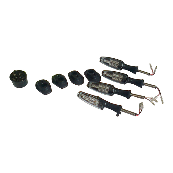
LED TURNSIGNAL SET
Description:
Applications:
DL1000AL4
Ref.
Contents
Ref. Description
Tools
(1) - Driver
Required
(2) Open end wrench
(8, 10, 12 mm)
(3) Ratchet
(4) Hexagon socket (3, 4, 5 mm)
(5) Socket (10, 12 mm)
(6) - Precision screwdriver
(7) Pliers
(8) Torque wrench
(9) Service manual
I N S T A L L A T I O N I N S T R U C T I O N S
Description
A
LED Turnsignal
B
Lead Wire
C
Bracket
D
Nut
E
Washer
F
IC Relay
G
Relay Holder
H
Earth Wire
I
3-Way Housing (M)
J
3-Way Housing (F)
K
Installation Instruction
Part Number: 99000-99008-100
Installation Time: 1.5 Hours
(1)
(4)
(7)
GENUINE SUZUKI ACCESSORIES
QTY
(2)
(3)
(5)
(6)
(8)
1/10
4
4
4
4
4
1
1
1
2
2
1
Publicidad

Manuales relacionados para Suzuki 99000-99008-100


Resumen de contenidos para Suzuki 99000-99008-100
- Página 1 1/10 I N S T A L L A T I O N I N S T R U C T I O N S LED TURNSIGNAL SET Description: Part Number: 99000-99008-100 Applications: DL1000AL4 Installation Time: 1.5 Hours Ref. Description...
- Página 2 5. Protect any items removed or to be installed from scratches by plac- ing them on a soft cloth first before putting them on the ground. 6. Use care not to cause any damage to the body of the vehicle during installation of the accessory. GENUINE SUZUKI ACCESSORIES...
- Página 3 Radiator heat shield. Disconnect the RH/LH handle switch coupler. NOTICE Be careful not to damage the hook of the coupler when removing the coupler from the Radiator heat shield. LH handle switch coupler LH handle switch coupler GENUINE SUZUKI ACCESSORIES...
- Página 4 Insert the precision screwdriver between the terminal Insert the precision screwdriver between the terminal and the coupler projection and the coupler projection RH handle switch coupler Black Black Sky blue Sky blue Light green Light green GENUINE SUZUKI ACCESSORIES...
- Página 5 3-Way Housing (F) 3-Way Housing (F) 6. Reinstall the RH/LH handle switch coupler into the original place on the Radiator heat shield. 7. Reinstall the parts which were removed in step (1) in the reverse order of removal. GENUINE SUZUKI ACCESSORIES...
- Página 6 Light blue ---> “Signal” nal of the IC Relay F. Signal Signal NOTICE Be sure of the position of the harness as shown in picture. (brown wire ---> “12V”, light blue wire ---> “Signal”) Brown ---> “12V” Brown ---> “12V” GENUINE SUZUKI ACCESSORIES...
- Página 7 LED Turnsignal LED Turnsignal step (1), Washer E, and Nut D into the LED Turnsignal A. Connect the Lead Wire B to the LED Turnsignal A. Washer Washer Lead Wire Lead Wire GENUINE SUZUKI ACCESSORIES...
- Página 8 NOTE: Adjust the right and left turnsignal to be the same direction. (90 degrees to the ground) 4. Connect the Lead Wire B to Right side the vehicle harness. Connect the Lead Connect the Lead Wire Wire GENUINE SUZUKI ACCESSORIES...
- Página 9 2. Disconnect the coupler of the standard Rear turnsignal and remove the turnsignals. Disconnect the coupler Disconnect the coupler 3. Mount the LED Turnsignal A Right side into the Bracket C. Bracket Bracket LED Turnsignal LED Turnsignal GENUINE SUZUKI ACCESSORIES...
- Página 10 If operation is OK, install the Rear frame cover and the Sport carrier in the reverse order of removal. NOTE: Adjust the right and left turnsignal to be the same direction. (90 degrees to the ground) GENUINE SUZUKI ACCESSORIES...
- Página 11 1/10 I N S T R U C T I O N S D E M O N T A G E KIT CLIGNOTANT LED Description: Code: 99000-99008-100 Modèle: DL1000AL4 Temps d’installation: 1,5 hr(s) Réf. Description Q.té Contenu Clignotant LED...
- Página 12 4. Enlever la clé de contact du contacteur et la ranger dans un endroit sûr. 5. Protéger des rayures toutes les pièces déposées ou à installer en les plaçant sur un chiffon plutôt qu’à même le sol. 6. Éviter d’endommager le véhicule pendant l’installation de l’acces- soire. GENUINE SUZUKI ACCESSORIES...
- Página 13 Débrancher les coupleurs de commodo de guidon D/G. AVIS Attention à ne pas endomma- ger le crochet des coupleurs à leur dépose du bouclier ther- mique du radiateur. Coupleur de commodo Coupleur de commodo de guidon G de guidon G GENUINE SUZUKI ACCESSORIES...
- Página 14 Insérer le tournevis de précision entre le contact et la Insérer le tournevis de précision entre le contact et la saillie du coupleur saillie du coupleur Sortir conducteurs coupleur droit Noir Noir Bleu ciel Bleu ciel Vert clair Vert clair GENUINE SUZUKI ACCESSORIES...
- Página 15 3-Coupleur(F) 6. Reposer les coupleurs de com- modo de guidon D/G dans leur position d’origine sur le bouclier thermique du radiateur. 7. Reposer les pièces déposées en (1) ci-dessus en procédant en ordre inverse de leur dépose. GENUINE SUZUKI ACCESSORIES...
- Página 16 Bleu ciel ---> “Signal” contacts “12V” & “Signal” du IC relais F. Signal Signal AVIS Bien implanter le faisceau de câbles comme illustré. (Fil brun ---> “12V”, fil bleu ciel ---> “Signal”) Brun ---> “12V” Brun ---> “12V” GENUINE SUZUKI ACCESSORIES...
- Página 17 Plaque d’origine Support Support d’origine (déposée en (1)), la Clignotant LED Clignotant LED rondelle E et l’écrou D sur le clignotant LED A. Raccorder le faisceau B au cli- gnotant LED A. Rondelle Rondelle Faisceau Faisceau Écrou Écrou GENUINE SUZUKI ACCESSORIES...
- Página 18 LED A au couvercle du cadre latéral. NOTE: Ajuster clignotants droit et gauche dans une même direction degrés par rapport au sol). 4. Raccorder le conducteur B au Côté droit faisceau de câbles. Raccorder le conducteur Raccorder le conducteur GENUINE SUZUKI ACCESSORIES...
- Página 19 2. Débrancher le coupleur des cli- gnotants arrière d’origine et déposer les clignotants. Débrancher le coupleur Débrancher le coupleur 3. Monter le support C sur le cli- Côté droit gnotant LED A. Support Support Clignotant LED Clignotant LED GENUINE SUZUKI ACCESSORIES...
- Página 20 Si tout est normal, reposer le couvercle du cadre arrière et le porte bagage en procédant en ordre inverse de la dépose. NOTE: Ajuster clignotants droit et gauche dans une même direction. degrés par rapport au sol) GENUINE SUZUKI ACCESSORIES...
- Página 21 1/10 M O N T A G E A N L E I T U N G LED-BLINKLEUCHTENSATZ Beschreibung: Teil-Nr.: 99000-99008-100 Verwendungen: DL1000AL4 Montagezeit: 1,5 hr(s) Beschreibung Stck Inhalt LED-Blinkleuchte Zuleitungskabel Halterung Mutter Scheibe IC-Relais Relaishalter Massekabel Dreiwegegehäuse (M) Dreiwegegehäuse (W) Montageanleitung Nr.
- Página 22 5. Abgenommene oder zu montierende Teile nicht einfach auf den Boden, sondern auf einen weichen Lappen legen, damit sie nicht ver- kratzt werden. 6. Darauf achten, dass die Fahrzeugkarosserie bei der Montage des Zubehörs nicht beschädigt wird. GENUINE SUZUKI ACCESSORIES...
- Página 23 Rechter Lenkerschalterstecker linken Lenkerschalterstecker (10 Klemmen : 8 Leitungen) vom Kühlerwärmeschutz abnehmen. Rechten/linken Lenkerschalter- stecker abtrennen. HINWEIS Beim Abnehmen des Steckers vom Kühlerwärmeschutz dar- auf achten, den Haken des Steckers nicht zu beschädigen. Linker Lenkerschalterstecker Linker Lenkerschalterstecker GENUINE SUZUKI ACCESSORIES...
- Página 24 Himmelblau Himmelblau Hellgrün Hellgrün Herausziehen der Leitung Steckervorsprung greift in Öffnung der Klemme Steckervorsprung drücken Zuleitungskabel herausziehen Präzisionsschraubendreher zwischen Klemme und Präzisionsschraubendreher zwischen Klemme und Steckervorsprung einsetzen Steckervorsprung einsetzen Rechter Lenkerschalterstecker Schwarz Schwarz Himmelblau Himmelblau Hellgrün Hellgrün GENUINE SUZUKI ACCESSORIES...
- Página 25 Seite Dreiwegegehäuse (M) Dreiwegegehäuse (M) anschließen. Dreiwegegehäuse (W) Dreiwegegehäuse (W) 6. Rechten/linken Lenkerschalter- stecker Kühlerwärme- schutz an ursprünglicher Stelle anbringen. 7. Die Teile, die in Schritt (1) abgenommenen wurden, in der umgekehrten Reihenfolge des Abnehmens wieder anbringen. GENUINE SUZUKI ACCESSORIES...
- Página 26 Hellblau ---> “Signal” und “Signal” des IC-Relais F anschließen. Signal Signal HINWEIS Sicherstellen, dass der Kabel- baum wie auf dem Bild gezeigt positioniert ist. (braunes Kabel ---> “12V”, hell- Braun ---> “12V” Braun ---> “12V” blaues Kabel ---> “Signal”) GENUINE SUZUKI ACCESSORIES...
- Página 27 2. Halterung C, die in Schritt (1) Standardplatte Standardplatte Halterung Halterung abgenommene Standardplatte, LED-Blinkleuchte LED-Blinkleuchte Scheibe E und Mutter D an der LED-Blinkleuchte A anbrin- gen. Das Zuleitungskabel B an die Scheibe Scheibe LED-Blinkleuchte A anschlie- Zuleitungskabel Zuleitungskabel ßen. Mutter Mutter GENUINE SUZUKI ACCESSORIES...
- Página 28 3. Die LED-Blinkleuchte A in der Rechte Seite Seitenrahmenabdeckung sichern. ANMERKUNG:Rechte linke Blinkleuchte auf glei- che Weise orientie- ren. (90 Grad zum Boden) 4. Das Zuleitungskabel B an den Rechte Seite Fahrzeugkabelbaum anschlie- ßen. Zuleitungskabel Zuleitungskabel anschließen anschließen GENUINE SUZUKI ACCESSORIES...
- Página 29 (Für rechte und linke Seite gelten dieselben Arbeitsschritte) 2. Den Stecker der hinteren Stan- dard-Blinkleuchten abtrennen und die Blinkleuchten abneh- men. Stecker abtrennen Stecker abtrennen 3. Die Halterung C an der LED- Rechte Seite Blinkleuchte A anbringen. Halterung Halterung LED-Blinkleuchte LED-Blinkleuchte GENUINE SUZUKI ACCESSORIES...
- Página 30 LED-Blinkleuchte als auch der Warnblinkbetrieb normal funktioniert. Wenn der Betrieb in Ordnung ist, hintere Rahmenabdeckung und Sport- träger in der umgekehrten Reihenfolge des Abnehmens anbringen. ANMERKUNG: Rechte linke Blinkleuchte auf glei- che Weise orientie- ren. (90 Grad zum Boden) GENUINE SUZUKI ACCESSORIES...
- Página 31 1/10 I N S T R U Z I O N I D I M O N T A G G I O SET INDICATORI DI DIREZIONE A LED Descrizione: Codice: 99000-99008-100 Applicabilità: DL1000AL4 Tempi installazione: 1.5 ora Ref. Descrizione Q.ta...
- Página 32 4. Rimuovere la chiave di accensione dall’interruttore e conservarla in un luogo sicuro. 5. Proteggere ogni elemento tolto o da installare da graffi mettendolo su di un panno soffice steso a terra. 6. Fare attenzione a non danneggiare la scocca del veicolo durante l’installazione dell’accessorio. GENUINE SUZUKI ACCESSORIES...
- Página 33 (10 terminali: 8 linee) dallo scudo termico del radiatore. Scollegare l’connettore (M/F) inte- ruttore manubrio destro/sinistro. AVVISO Nel rimuoverlo dallo scudo ter- mico, fare attenzione a non danneggiare gancio dell’accoppiatore. Connettore (M/F) interuttore Connettore (M/F) interuttore manubrio sinistro manubrio sinistro GENUINE SUZUKI ACCESSORIES...
- Página 34 Inserire il cacciavite di precisione fra il terminale e la Inserire il cacciavite di precisione fra il terminale e la linguetta interna dell'accoppiatore linguetta interna dell'accoppiatore Interruttore destro Nero Nero Azzurro Azzurro Verde chiaro Verde chiaro GENUINE SUZUKI ACCESSORIES...
- Página 35 6. Rimettere l’connettore (M/F) inte- Connettore femmina a 3 vie (F) Connettore femmina a 3 vie (F) ruttore manubrio destro/sinistro nella posizione originale sullo scudo termico del radiatore. 7. Installare le parti rimosse in (1) nell’ordine inverso a quello di rimozione. GENUINE SUZUKI ACCESSORIES...
- Página 36 Azzurro --> “Signal” Azzurro --> “Signal” “Signal” del IC Relè F. Signal Signal AVVISO Controllare la posizione del cablaggio nel modo visto in figura. (cablaggio marrone ---> “12V”, cablaggio azzurro ---> “Signal”) Marrone ---> “12V” Marrone ---> “12V” GENUINE SUZUKI ACCESSORIES...
- Página 37 Piastra standard Piastra standard Staffa Staffa standard (rimossa in (1)), la Indicatore Indicatore rondella E, ed il dado D direzione LED direzione LED nell’indicatore direzione LED Rondella Rondella Collegare cablaggio all’indicatore direzione LED A. Cablaggio Cablaggio Dado Dado GENUINE SUZUKI ACCESSORIES...
- Página 38 NOTA: Regolare gli indicatori di direzione destro e sinistro orientandoli allo stesso modo. (90 gradi al suolo) 4. Collegare il cablaggio B al Lato destro fascio fili del veicolo. Cablaggio Cablaggio GENUINE SUZUKI ACCESSORIES...
- Página 39 2. Scollegare l’accoppiatore dell’indi- catore di direzione posteriore standard e rimuovere gli indica- tori di direzione. Scollegare l’accoppiatore Scollegare l’accoppiatore 3. Installare la staffa C nell’indica- Lato destro tore direzione LED A. Staffa Staffa Indicatore Indicatore direzione LED direzione LED GENUINE SUZUKI ACCESSORIES...
- Página 40 Se il funzionamento è normale, installare la copertura del telaio posteri- ore e il portapacchi sportivo nell’ordine inverso a quello di rimozione. NOTA: Regolare gli indicatori di direzione destro e sinistro orientandoli allo stesso modo. (90 gradi al suolo) GENUINE SUZUKI ACCESSORIES...
- Página 41 I N S T R U C C I O N E S P A R A E L M O N T A J E JUEGO DE LUCES DIRECCIONALES LED Descripción: N°de de parte: 99000-99008-100 Aplicación: DL1000AL4 Tiempo de montaje: 1,5 hr(s) Ref.
- Página 42 5. Proteja cada pieza que haya quitado o que vaya a instalar para que no se raye colocándola primero sobre un paño blando antes de ponerla en el suelo. 6. Tenga cuidado para no causar ningún daño a la carrocería del vehí- culo durante la instalación de un accesorio. GENUINE SUZUKI ACCESSORIES...
- Página 43 AVISO Tenga cuidado de no dañar el gancho del acople cuando quite el acople de la pantalla térmica del radiador. Acople de interruptor del Acople de interruptor del manillar izquierdo manillar izquierdo GENUINE SUZUKI ACCESSORIES...
- Página 44 Inserte el destornillador plano fino entre el terminal y cable conductor. la lengueta de sujeciópn del acople. la lengueta de sujeciópn del acople. Acople del interruptor derecho Negro Negro Azul cielo Azul cielo Verde claro Verde claro GENUINE SUZUKI ACCESSORIES...
- Página 45 Acople de 3 vías (hembra) del lado izquierdo. 6. Instale el acople de interrupto- manillar derecho/ izquierdo en el lugar original de la pantalla térmica del radiador. 7. Instale las partes que fueron quitadas orden inverso al del desmontaje. GENUINE SUZUKI ACCESSORIES...
- Página 46 “12 V” y “señal” del relé IC F. Signal Signal AVISO Asegúrese de posicionar el mazo de cables como se mues- tra en la imagen. (Cable marrón -> “12 V”, cable azul claro -> “Signal”) Marrón ---> “12 V” Marrón ---> “12 V” GENUINE SUZUKI ACCESSORIES...
- Página 47 C, la placa estándar (quitada Direccional LED Direccional LED en (1)), la arandela E y la tuerca D en el direccional LED Conecte el cable (conductor) B Arandela Arandela en el direccional LED A. Cable principal Cable principal Tuerca Tuerca GENUINE SUZUKI ACCESSORIES...
- Página 48 NOTA: Ajuste los direccionales derecho e izquierdo de manera que queden a 90° con relación al suelo. 4. Conecte el cable B al mazo de Lado derecho cables del vehículo. Conecte el cable Conecte el cable conductor conductor GENUINE SUZUKI ACCESSORIES...
- Página 49 2. Desconecte el acople del inter- mitente trasero estándar y quite los direccionales. Desconecte los acoples Desconecte los acoples 3. Instale el soporte C en el direc- Lado derecho cional LED A. Soporte Soporte Direccional LED Direccional LED GENUINE SUZUKI ACCESSORIES...
- Página 50 Si la operación es normal, instale la cubierta de bastidor trasera y el por- taequipaje en el orden inverso al del desmontaje. NOTA: Ajuste direccionales derecho e izquierdo de manera que queden a 90° con relación al suelo. GENUINE SUZUKI ACCESSORIES...