Publicidad
Idiomas disponibles
Idiomas disponibles
Enlaces rápidos
Instrucciones generales para la instalación, uso y mantenimiento
Instructions générales pour l'instalation, l'utilisation et l'entretien
General instructions for installation, use and maintenance
Allgemeine bedienungssanleitung zur installation, bedienung und
Instruccioni generali per l´ installazione ,i´uso e la manutenzione
Mod:
CG9-20; CG9-20 H
CG9-40; CG9-40 H; CG9-40 I
CG9-60; CG9-60 H; CG9-60 I
CG9-41; CG9-41 H; CG9-41 I
CG9-61; CG9-61 H; CG9-61 I; CG9-61 OP
CG9-82; CG9-82 I
CG9-10
CG9-11
CG9-51
CGF9-120 I; CGF9-120 D; CGF9-121 I; CGF9-121 D
CGE9-41
COCINAS A GAS
FOURNEAUX A GAZ
GAS RANGES
wartung
GAS HERDE
CUCINE A GAS
U026508-
01
Publicidad

Manuales relacionados para Fagor CG9-40 I CG9-60


Resumen de contenidos para Fagor CG9-40 I CG9-60
- Página 1 Instrucciones generales para la instalación, uso y mantenimiento COCINAS A GAS Instructions générales pour l’instalation, l’utilisation et l’entretien FOURNEAUX A GAZ General instructions for installation, use and maintenance GAS RANGES Allgemeine bedienungssanleitung zur installation, bedienung und wartung GAS HERDE Instruccioni generali per l´ installazione ,i´uso e la manutenzione CUCINE A GAS Mod: CG9-20;...
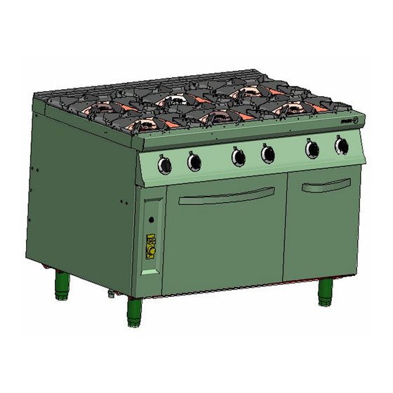
- Página 2 CG9-20 CG9-40 CG9-60 CG9-41...
- Página 3 CG9-61 G: Entrada de gas : Gas inlet VM: Grifo válvula de mesa VM: Table tap-valve VH: Válvula termostática de horno VH: Oven thermostatic valve CG9-61 OP G: Entrada de gas G: Gas inlet VM: Grifo válvula de mesa VM: Table tap-valve VH: Válvula termostática de horno VH: Oven thermostatic valve CG9-82...
- Página 4 CG9-11 CG9-51 G: Entrada de gas G: Gas inlet VM: Grifo válvula de mesa VM: Table tap-valve VH: Válvula termostática de horno VH: Oven thermostatic valve VP: Válvula termostática de plancha VP: Hotplate thermostatic valve CGF9-120 I...
- Página 5 CGF9-120 D CGF9-121 D 5250 CGF9-121 I Entrata gas VM: Rubinetto-valvola del piano cottura VH: Valvola termostatica del forno...
- Página 6 CGE9-41 G: Gas inlet VM: Table tap-valve VH: Oven thermostatic valve...
- Página 7 Fig 5...
- Página 9 No obstante, le aconsejamos estudie detenidamente este manual copilado por los jefes de cocina de FAGOR, únicamente así podrá beneficiarse al máximo de las múltiples posibilidades y ventajas que le brinda este aparato.
- Página 10 Características técnicas(Tabla nº 1) CG9-61 Modelo CG9-20 CG9-40 CG9-41 CG9-60 CG9-61 CG9-82 CG9-11 CG9-10 CGE9-41 Anchura 1275 1275 1275 1700 DIMENSIONES (mm) Profundidad EXTERNAS Altura Anchura DIMENSIONES (mm) Profundidad HORNO Altura PESO NETO (kg) 5.250 (Mesa) 8.000 (Mesa) 10.200 (Mesa) NÚMERO DE QUEMADORES 10.850 (Mesa)
- Página 11 (Tabla nº 3) Modelo CG9-40 I CG9-60 I CG9-41 I CG9-61 I CG9-82 I Anchura 1275 1275 1700 DIMENSIONES (mm) Profundidad EXTERNAS Altura Anchura DIMENSIONES (mm) Profundidad HORNO Altura PESO NETO (kg) 5.250 (Mesa) 6.000 (Mesa) NÚMERO DE QUEMADORES 8.600 (Horno) 6.000 (Mesa) G-20 2,09...
- Página 12 Potencias de los quemadores (Tabla nº 5) QUEMADOR QUEMADOR QUEMADOR QUEMADOR QUEMADOR HORNO HORNO QUEMADOR 10.200 10850 5.250 6.000 8.000 8.600 5.78 6,42 8,14 10,7 11,75 POTENCIA (Poder calorif. inf.) kW/h 5.250 6.000 8.000 10.200 10.850 15.300 8.600 (Poder calorif. sup.) Kcl/h TOTAL Gases de referencia (Tabla nº...
- Página 13 Diámetro de inyectores y regulación (Tabla nº8) QUEMADOR QUEMADOR QUEMADOR QUEMADOR QUEMADOR Poder calorífico 5.250 6.000 8.000 10.200 10.850 FAMILIA / GAS inferior φInyector φInyector φInyector φInyector φInyector (mm) (mm) (mm) (mm) (mm) (mm) (mm) (mm) (mm) (mm) (mm) (mm) (mm) (mm) G-110...
- Página 14 Posiciones y temperaturas (aproximadas) del horno (Tabla nº 10) HORNO GAS HORNO ELECTRICO 170-190ºC 160-180ºC 125ºC 90ºC 180-200ºC 180-240ºC 175ºC 120ºC 215ºC 170ºC 250ºC 200ºC 180-200ºC 160-180ºC 265ºC 230ºC 285ºC 260ºC 180-200ºC 160-180ºC 310ºC 280ºC 340ºC 315ºC 160-180ºC 190-210ºC...
- Página 15 1.- INSTALACIÓN Emplazamiento y nivelación ∗ El emplazamiento y la instalación tanto eléctrica como de gas, debe realizarse siempre por un TÉCNICO AUTORIZADO, respetando las normas de cada país. ∗ Es conveniente instalar una campana extractora para el buen funcionamiento. ∗...
- Página 16 Transformación de los quemadores de mesa y horno Sustitución de los inyectores. Desmontar los inyectores “I” (Fig. 3) y sustituirlos por los adecuados según el gas a utilizar (Tabla 8) Regulación aire quemadores. Posicionar el regulador de aire “C” (Fig. 3) a la medida “H” (Tabla 8) según el gas a utilizar. Transformación de pilotos Para transformar a GAS NATURAL, se deberá...
- Página 17 posiciones MAXIMO (Fig. 6, Nº 3). Posición MINIMO (Fig. 6, Nº 4). Llegando a esa posición soltar el mando. IMPORTANTE: Para pasar de posición MAXIMO a otra cualquiera, se deberá siempre pulsar el mando. Apagado de los quemadores de mesa. Si está...
- Página 18 3.-MANTENIMIENTO Limpieza diaria. Para que el aparato se mantenga como el primer día, es conveniente seguir las siguientes instrucciones: ∗ No utilizar detergentes arenosos y abrasivos para su limpieza. ∗ No utilizar manguera de agua para la limpieza del aparato. ∗...
- Página 19 ∗ Como norma general siempre que se sustituya cualquier componente funcional, se debe comprobar que la llave general del gas está cerrada y no hay fuego en las proximidades del aparato. 4.-RECOMENDACIÓN DE PROTECCIÓN AMBIENTAL Al terminar su vida útil, este producto no debe tirarse en un contenedor de basuras estándar, sino que debe dejarse en un punto de recogida de deshechos eléctricos y equipamiento electrónico para ser reciclado.
- Página 20 à comprendre. Cependant, nous vous conseillons d'étudier attentivement ce manuel compilé par les chefs cuisiniers de FAGOR. Ce n'est qu'ainsi qu'il vous sera possible de tirer le plus grand parti des multiples possibilités et avantages que vous offre cet appareil.
- Página 21 Caractéristiques techniques (Tableau nº 1) Modele CG9-20 CG9-40 CG9-41 CG9-60 CG9-61 CG9-82 CG9-11 CG9-10 CG9-61 OP CGE9-41 Largeur 1275 1275 1275 1700 DIMENSIONS (mm) Profondeur EXTÉRIEURES Hauteur Largeur DIMENSIONS (mm) Profondeur FOUR Hauteur POIDS NET (KG.) 5.250 (Table) 8.000 (Table) 10.200 (Table) NOMBRE DE BRÛLEURS...
- Página 22 (Tableau nº 3) Modele CG9-40 I CG9-60 I CG9-41 I CG9-61 I CG9-82 I Largeur 1275 1275 1700 DIMENSIONS (mm) Profondeur EXTÉRIEURES Hauteur Largeur DIMENSIONS (mm) Profondeur FOUR Hauteur POIDS NET (KG.) 5.250 (Table) 6.000 (Table) NOMBRE DE BRÛLEURS 8.600 (Four) 6.000 (Table) G-20 2,09...
- Página 23 Puissance des brûleurs (Tableau nº 5) BRÛLEUR BRÛLEUR BRÛLEUR FOUR FOUR BRÛLEUR BRÛLEUR BRÛLEUR 5.250 6.000 8.000 10.200 10850 8600 (Puissance calorifique 5.78 6,42 8,14 10,7 11,75 inf.) kW/h PUISSANCE TOTALE (Puissance calorifique 5.250 6.000 8.000 10.200 10.850 15.300 8.600 sup.) Kcal/h Gaz de référence (Tableau nº...
- Página 24 Diamètre des injecteurs et réglage (Tableau nº8) BRÛLEUR BRÛLEUR BRÛLEUR BRÛLEUR BRÛLEUR Puissance 5.2500 6.000 8.000 10.200 10.850 FAMILLE/GAZ calorifique Ø Ø Ø Ø Ø Injecteu inférieure Injecteur Injecteur Injecteur Injecteur (mm) (mm) (mm) (mm) (mm) (mm) (mm) (mm) (mm) (mm) (mm) (mm)
- Página 25 Positions et températures (approximatives) du four (Tableau nº 10) FOUR GAZ FOUR ÉLECTRIQUE 220-280ºC 230-250ºC 125ºC 90ºC 175ºC 120ºC 215ºC 170ºC 250ºC 200ºC 250-300ºC 230-250ºC 265ºC 230ºC 285ºC 260ºC 310ºC 280ºC 340ºC 315ºC...
- Página 26 1.-INSTALLATION: Mise en place et nivellement ∗ La mise en place ainsi que l'installation électrique et de gaz doivent toujours être effectuées par un TECHNICIEN AGRÉÉ, conformément aux normes de chaque pays. ∗ Il convient d’installer une hotte aspirante pour un fonctionnement correct. ∗...
- Página 27 Démontez les injecteurs “I” des brûleurs (Fig. 3) et remplacez-les par les injecteurs adaptés au gaz à utiliser (Tableau Réglage air brûleurs. Placez le régulateur d'air “C” (Fig. 3) à la mesure “H” (Tableau 8) suivant le gaz à utiliser Transformation des voyants Pour passer au GAZ NATUREL, il faudra procéder de la façon suivante: desserrer la vis “A”...
- Página 28 Presser l’interrupteur “P1” (Fig. 8), tout en pressant plusieurs fois le piézoélectrique du voyant “P3” (Fig. 8), jusqu’à ce que la flamme du voyant reste allumée. Maintenir “P1” appuyé à fond, jusqu’à ce que, si on le lâche, la flamme du voyant reste stable. A partir de ce moment, pour allumer le brûleur, tourner la commande “P2”...
- Página 29 ∗ Le nettoyage périodique des voyants est important pour éviter leur obstruction. Indications pour l’utilisation du four. ∗ Avant d’utiliser le four, il est recommandé d’en nettoyer l’intérieur avec un chiffon imprégné d’eau savonneuse, afin d’éviter les mauvaises odeurs lors de la mise en service. ∗...
- Página 30 4.-RECOMMANDATION DE PROTECTION DE L’ENVIRONNEMENT En fin de vie utile, ce produit ne doit pas être jeté dans un conteneur d’ordures standard, mais il doit être déposé dans un point de récupération d’appareils électriques et d’équipements électroniques afin d’être recyclé. Ce fait est confirmé...
- Página 31 Nevertheless, we recommend you thoroughly read this manual compiled by FAGOR's kitchen supervisors, in order to benefit to the maximum from the multiple possibilities and advantages this appliance offers you.
- Página 32 Technical specifications (Table no. 1) Model CG9-20 CG9-40 CG9-41 CG9-60 CG9-61 CG9-82 CG9-11 CG9-10 CGE9-41 Width 1275 1275 1700 EXTERNAL (mm) Depth DIMENSIONS Height Width OVEN (mm) Depth DIMENSIONS Height Net weight (kg) 5,250 (Table) 8,000 (Table) 10,200 (Table) NUMBER OF BURNERS 10,850 (Table) 8,600 (Oven)
- Página 33 (Table no. 3) Model CG9-40I CG9-60I CG9-41I CG9-61I CG9-82I Width 1275 1275 1700 EXTERNAL (mm) Depth DIMENSIONS Height Width OVEN (mm) Depth DIMENSIONS Height Net weight (kg) 5,250 (Table) 6,000 (Table) NUMBER OF BURNERS 8,600 (Oven) 6,000 (Oven) G-20 2.09 3.42 2.78 4.11...
- Página 34 Burner powers (Table no. 5) BURNER BURNER BURNER BURNER BURNER OVEN OVEN BURNER 10,200 10850 5,250 6,000 8,000 8000 8.600 5.78 6,42 8,14 10,7 11,75 (Lower calorific power) H POWER (Upper calorific power) 5.250 6.000 8.000 10.200 10.850 15.300 8.600 OUTPUT Kcl/H Reference gases (Table no.
- Página 35 Injector diameter and adjustment (Table no. 8) BURNER BURNER BURNER BURNER BURNER 5,250 6,000 8,000 10,200 10,850 Lower Calorific FAMILY / GAS φ φ Power φ Injector φ Injector φInjector Injector Injector (mm) (mm) (mm) (mm) (mm) (mm) (mm) (mm) (mm) (mm) (mm)
- Página 36 Oven positions and temperatures (approximate) (Table no. 10) GAS OVEN ELECTRIC OVEN 220-280ºC 230-250ºC 125ºC 90ºC 175ºC 120ºC 215ºC 170ºC 250ºC 200ºC 250-300ºC 230-250ºC 265ºC 230ºC 285ºC 260ºC 310ºC 280ºC 340ºC 315ºC...
- Página 37 1.-INSTALATION: Positioning and levelling ∗ The positioning and electrical and gas installation should always be carried out by an AUTHORISED TECHNICIAN, observing the standards of each country. ∗ It is advisable to install an extraction hood for the optimum operation of the appliance. ∗...
- Página 38 Turn the air regulator “C” until the flame steadies. To convert to TOWN GAS, the adjustment of the pilot flame will be carried out turning the adjusting screw “B” until the flame is stable. Table taps minimum flow adjustment IMPORTANT: before adjustment, the burner must have fully operating for at least 15 minutes. For NATURAL GAS and TOWN GAS, turn adjustment screw “F”...
- Página 39 Turning the electric oven on. Once the heating system has been decided upon (Fig. 10), turn the “MHG” control to the desired position (Fig. 9). The pilot “P2” (Fig. 9) (green) will then turn on, indicating that the oven is ready for operation. Select the temperature according to table no.
- Página 40 4.-ENVIRONMENTAL PROTECTION RECOMMENDATION On ending its useful life, this product must not be thrown away in a standard rubbish bin, but must be left in an electrical waste and electronic equipment collection point for recycling. This is confirmed by the symbol on the product, user manual, or packaging. Depending on the symbol, the materials can be recycled.
- Página 41 Nehmen Sie sich einige Minuten Zeit, begeben Sie sich mit diesem Handbuch zum Gerät und „Hand ans Werk”: Die leicht verständlichen Bildinformationen ersetzen die bisher verwendeten Volltextseiten. Allerdings raten wir Ihnen dazu, das vorliegende, von den FAGOR-Küchenchefs verfasste Handbuch gründlich durchzulesen, da Sie nur so in den Genuss der vielfältigen Möglichkeiten und Vorteile dieses Gerätes kommen können.
- Página 42 Technische Eigenschaften (Tabelle Nr. 1) CG9-61 CGE9- Modell CG9-20 CG9-40 CG9-41 CG9-60 CG9-61 CG9-82 CG9-11 CG9-10 Breite 1275 1275 1275 1700 AUSSEN- Tiefe (mm) ABMESSUNGEN Höhe Breite GERÄTEABMESSUNGEN Tiefe (mm) Höhe NETTOGEWICHT (KG) 5.250 (Tisch) 8.000 (Tisch) 10.200 (Tisch) ANZAHL BRENNER 10.850 (Tisch) 8.600 (Ofen) 7650 (Ofen)
- Página 43 (Tabelle Nr. 3) Modell CG9-40 I CG9-60 I CG9-41 I CG9-61 I CG9-82 I Breite 1275 1275 1700 AUSSEN- (mm) Tiefe ABMESSUNGEN Höhe Breite GERÄTEABMESSUNGEN (mm) Tiefe Höhe NETTOGEWICHT (KG) 5.250 (Tisch) 6.000 (Tisch) ANZAHL BRENNER 8.600 (Ofen) 6.000 (Tisch) G-20 2,09 3,42...
- Página 44 Bezugsgase (Tabelle Nr 6) Kcal/m³ Kcal/kg STADTGAS ERDGAS PETROLEUMGAS G-110 G-130 G-150 G-20 G-25 G-25.1 GZ-35 G-30 G-31 UNTERER 3.515 5.960 4.542 8.573 7.372 7.000 5.851 10.901 11.066 HEIZWERT Luftverbrauch (Tabelle Nr. 7) Mod. Für die Verbrennung erforderlicher Luftverbrauch Nm³/h CG9-10 CG9-20 CG9-20 H...
- Página 45 PILOTBRENNE PILOTBRENNE BRENNER BRENNER BRENNER ZÜNDBEREICH Unterer R TISCH R OFEN 6000 OFEN 8600 OFEN 16000 ( OFEN OP) (OFEN OP) FAMILIE/GAS φ φ Heizwert φ Injektor φ Injektor φ Injektor φ Injektor D(mm) Injektor Injektor(m (mm) (mm) (mm) (mm) (mm) (mm) (mm)
- Página 46 Positionen und (ungefähre) Temperaturen des Ofens (Tabelle Nr. 10) GASOFEN ELEKTROOFEN 170-190ºC 160-180ºC 125ºC 90ºC 180-200ºC 180-240ºC 175ºC 120ºC 215ºC 170ºC 250ºC 200ºC 180-200ºC 160-180ºC 265ºC 230ºC 285ºC 260ºC 180-200ºC 160-180ºC 310ºC 280ºC 340ºC 315ºC 160-180ºC 190-210ºC...
- Página 47 1.-INSTALLATION: Aufstellung und Nivellierung Der elektrische Anschluss des Gerätes darf nur von einem AUTORISIERTEN TECHNIKER unter Einhaltung der jeweils geltenden Landesbestimmungen vorgenommen werden. ∗ Die Netzspannung muss mit der auf dem Typenschild angegebenen Spannung übereinstimmen. ∗ Für den Anschluss muss ein Kabelschlauch aus Polychloropren oder einem anderen Werkstoff mit ähnlichen Eigenschaften (H05RN-F) benutzt werden) ∗...
- Página 48 WICHTIG: Um von der MAXIMAL-Stellung in eine andere Stellung zu wechseln, muss stets der Schalter gedrückt werden. Ausschalten der Tischbrenner Wenn Sie sich in den Stellungen MAXIMAL, MINIMAL oder in einer der Zwischenstellungen befinden, muss der Schalter gedrückt, im Uhrzeigersinn in die Stellung PILOTBRENNER gedreht (Abb. 6, Nr. 2) und dann losgelassen werden.
- Página 49 3.-WARTUN: Tägliche Reinigung. Um das Gerät stets im optimalen Zustand zu halten, sollten folgende Anweisungen befolgt werden: ∗ Zur Reinigung dürfen weder sandhaltige noch scheuernde Reinigungsmittel verwendet werden. ∗ Zur Reinigung des Gerätes darf kein Druckwasser verwendet werden. ∗ Es wird empfohlen, die Fettauffangschalen täglich zu reinigen. ∗...
- Página 50 ∗ Beim Auswechseln von Funktionskomponenten muss geprüft werden, dass der Haupthahn für Gas geschlossen ist und sich keine offene Flamme in Gerätenähe befindet. 4.-UMWELTSCHUTZEMPFEHLUNG Sobald Ihr Gerät ausgedient hat, darf es nicht in den Müll gegeben werden, sondern muss an einer Sammelstelle für Elektromüll und elektronische Geräte zwecks Entsorgung abgegeben werden.
- Página 51 Ciò nonostante, consigliamo di studiare attentamente il presente manuale redatto dai responsabili di cucina di FAGOR, in modo tale di trarre i massimi vantaggi dalle molteplici possibilità che offre il presente apparecchio. Conservare questo manuale nelle vicinanze dell’apparecchio e in un luogo sempre accessibile.
- Página 52 Caratteristiche tecniche (Tabella nº 1) CGE9- Modello CG9-20 CG9-40 CG9-41 CG9-60 CG9-61 CG9-61 OP CG9-82 CG9-11 CG9-10 Larghezza 1275 1275 1275 1700 DIMENSIONI (mm) Profondità ESTERNE Altezza Larghezza DIMENSIONI (mm) Profondità FORNO Altezza PESO NETTO (KG.) 5.250 (Piano) 8.000 (Piano) 10.200 (Piano) NÚMERO DEI BRUCIATORI...
- Página 53 (Tabella nº 3) Modello CG9-40 I CG9-60 I CG9-41 I CG9-61 I CG9-82 I Larghezza 1275 1275 1700 DIMENSIONI (mm) Profondità ESTERNE Altezza Larghezza DIMENSIONI (mm) Profondità FORNO Altezza PESO NETTO (KG.) 5.250 (Piano) 6.000 (Piano) NÚMERO DEI BRUCIATORI 8.600 (Forno) 6.000 (Piano) G-20 2,09...
- Página 54 Gas di riferimento (Tabella nº 6) Kcal/m³ Kcal/kg GAS CITTÀ GAS NATURALE G.P.L. G-110 G-130 G-150 G-20 G-25 G-25.1 GZ-35 G-30 G-31 POTERE CALORIFICO 3.515 5.960 4.542 8.573 7.372 7.000 5.851 10.901 11.066 INFERIORE Consumo d’aria (Tabella nº 7) MODELLO Consumo d’aria necessario per la combustione Nm³/h CG9-10 CG9-20...
- Página 55 BRUCIATOR BRUCIATO SEZIONE BRUCIATORE E 6000 RE 8600 Potere ACCENSIONE SPIE PIANO SPIE FORNO 16000 (FORNO OP) (FORNO OP) FAMIGLIA/GAS calorifico FORNO FORNO φ φ inferiore φ Iniettore φ Iniettore φ Iniettore φ Iniettore (mm) D(mm) Iniettore Iniettore (mm) (mm) (mm) (mm) (mm)
- Página 56 Posizioni e temperature (approssimative) del forno (Tabella nº 10) FORNO A GAS FORNO ELETTRICO 220-280ºC 230-250ºC 125ºC 90ºC 250-300ºC 230-250ºC 175ºC 120ºC 215ºC 170ºC 220-250ºC 210-240ºC 250ºC 200ºC 265ºC 230ºC 200-230ºC 200-220ºC 285ºC 260ºC 310ºC 280ºC 220-250ºC 190-210ºC 340ºC 315ºC...
- Página 57 1.-INSTALLAZIONE: Ubicazione e livellamento L’ubicazione e l’installazione sia elettrica che a gas, dovrà essere effettuata da un TECNICO AUTORIZZATO, rispettando le norme vigenti in ciascun paese. ∗ Per il corretto funzionamento dell’apparecchio, è indispensabile installare una campana estrattrice. ∗ Ubicare l’apparecchio in un locale ben ventilato. ∗...
- Página 58 Regolazione aria dei bruciatori. Posizionare il regolatore dell’aria “B” (Fig. 3) al grado “H” (Tabella 8) secondo il tipo di gas che si vuole utilizzare. Trasformazione delle spie d’accensione Per modificarlo a GAS NATURALE, si dovrà procedere nel seguente modo: svitare la vite “A” della Fig. 4 (particolare A).
- Página 59 Da questo momento in poi, per accendere il bruciatore, girare la manopola “P2” del termostato (Fig. 8) in senso antiorario, impostandolo sulla posizione corrispondente alla temperatura selezionata (vedere tabella nº 10). Per aiutare l’accensione del forno, con l’acquisto di ciascuna cucina è inclusa una leva di sollevamento per le piastre con cui si può...
- Página 60 ∗ In tutti gli apparecchi, è include come accessorio un ago per la pulizia che permette la pulizia dei bruciatori del piano di cottura. Accessorio per togliere la porta del forno. ∗ In tutti gli apparecchi dotati di forno, sono incluse come accessori delle squadre per un montaggio / smontaggio semplice del forno.