
Manuales relacionados para Xylem Goulds VIT


Resumen de contenidos para Xylem Goulds VIT
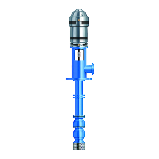
- Página 1 INSTRUCTION MANUAL IMVITR01 MODEL VIT VERTICAL INDUSTRIAL TURBINE PUMPS INSTALLATION, OPERATION AND MAINTENANCE INSTRUCTIONS...
-
Página 2: Owner's Information
Foreword This manual provides instructions for the Installation, Operation, and Maintenance of the Goulds Water Technology Vertical Industrial Turbine Pumps. This manual covers a standard product. For special options, supplemental instructions are available. This manual must be read and understood before installation and start-up. -
Página 3: Tabla De Contenido
Table of Contents SUBJECT PAGE SECTION 1 – Safety ..............................4 Safety Instructions ..............................4 General Precautions ..............................4 SECTION 2 – General Information ..........................4 Introduction ................................4 Receiving and Checking ............................4 Materials and Equipment Required ........................... 5 Storage .................................. -
Página 4: Section 1 - Safety
Safety Instructions – SECTION 1 • Other personal protective equipment to protect against hazardous/toxic fluid. TO AVOID SERIOUS OR FATAL PERSONAL INJURY Maintenance Safety: OR MAJOR PROPERTY DAMAGE, READ AND • Always lock out power. FOLLOW ALL SAFETY INSTRUCTIONS IN THE •... -
Página 5: Materials And Equipment Required
EQUIPMENT REQUIRED Storage Preparation The material and equipment necessary for installation of the pump will vary with the size of the pump and the Goulds Water Technology VIT Pumps require proper type of installation. preparation for storage and regular maintenance during storage. -
Página 6: General Description
Uncontrolled Long Term Storage Preparations Discharge Head The discharge head is either a cast iron head or a When applicable to the pump, storage periods over six fabricated head. Ports are provided for connecting the months require the preceding storage procedure and pressure gauge, stuffing box bypass return and lubricator storage preparation plus the following: connections. -
Página 7: Typical Drawings
DISCHARGE HEAD ASSEMBLY ITEM DESCRIPTION DISCHARGE HEAD MOTOR SUPPORT HEADSHAFT COUPLING ASSEMBLY SEAL HOUSING SEAL HOUSING BEARING MECHANICAL SEAL COLUMN FLANGE SEAL HOUSING GASKET COLUMN ASSEMBLY COLUMN PIPE COLUMN COUPLING LINESHAFT LINESHAFT COUPLING BEARING RETAINER LINESHAFT BEARING BOWL ASSEMBLY BOWL SHAFT DISCHARGE BOWL DISCHARGE BEARING INTERMEDIATE BOWL... - Página 8 DISCHARGE HEAD ASSEMBLY ITEM DESCRIPTION DISCHARGE HEAD HEADSHAFT COUPLING ASSEMBLY SEAL HOUSING SEAL HOUSING BEARING MECHANICAL SEAL COLUMN ASSEMBLY COLUMN PIPE COLUMN BOLTING LINESHAFT LINESHAFT COUPLING BEARING RETAINER LINESHAFT BEARING BOWL ASSEMBLY BOWL SHAFT INTERMEDIATE BOWL INTERMEDIATE BOWL BEARING IMPELLER TAPERLOCK WEAR RING (OPTIONAL) HEX BOLT...
-
Página 9: Head Assembly
HEAD ASSEMBLY ITEM DESCRIPTION DISCHARGE HEAD ADJUSTING NUT HEADSHAFT O-RING TENSION PLATE TENSION NUT OILER COLUMN FLANGE GIB KEY TENSION PLATE GASKET COLUMN ASSEMBLY TUBE NIPPLE COLUMN NIPPLE COLUMN LOCK RING COLUMN PIPE COLUMN COUPLING LINESHAFT LINESHAFT COUPLING OIL TUBE LINESHAFT BEARING TUBE STABILIZER BOWL ASSEMBLY... - Página 10 HEAD ASSEMBLY ITEM DESCRIPTION DISCHARGE HEAD ADJUSTING NUT HEADSHAFT O-RING TENSION PLATE TENSION NUT OIL RESERVOIR COLUMN FLANGE GIB KEY TENSION PLATE GASKET COLUMN ASSEMBLY TUBE NIPPLE COLUMN PIPE COLUMN BOLTING LINESHAFT LINESHAFT COUPLING OIL TUBE LINESHAFT BEARING TUBE STABLIZER BOWL ASSEMBLY BOWL SHAFT DISCHARGE BOWL...
-
Página 11: Section 3 - Installation
Installation – SECTION 3 5. Carefully lower the sub base onto the foundation bolts. Hand tighten the nuts. FOUNDATION AND PIPING 6. Leveling the sub base may be done by several SUB BASE (SOLE PLATE) INSPECTION methods. Two common methods are: Sub base and sole plate are terms in common use to describe a general class of solid steel plates mounted A. -
Página 12: Pump Installation
9 Sylvan Way, Parsippany, NJ 07054-3802 and must be to lower unit until the discharge head flange engages reviewed prior to pump installation. and rests firmly on the plate, then secure with capscrews provided. Never draw piping into place by forcing WARNING 5. -
Página 13: Installing The Column
6. Attach a sling to the elevator clamps, eyebolts, With a keyed coupling or lifting bail and hoist it into position over the insert the key into the foundation opening. (See Figure 7). pump shaft. Lower the sleeve over the pump shaft, 7. - Página 14 10. Install the top shaft or stub shaft and coupling. If 7. With lineshaft in proper position on the coupling, the pump is equipped with column adjusting nipple, remove tail rope and screw lineshaft into coupling install it with longer threaded end upward. Screw until resistance is felt.
-
Página 15: Installing The Discharge Head
15. Install the top shaft or stub shaft and coupling. be centered by shimming the head base and the sub base (or the foundation). Do not drop any foreign object into the 10. Rotate the shaft approximately 90º. Check again CAUTION bowl assembly. -
Página 16: Installing The Mechanical Seal
7. The stuffing box is shipped with both ports plugged. 7. Install the O-ring or gasket, between the seal If the discharge pressure is over 100 psi, remove the housing and seal. Install the seal over the shaft and plug on Port “A” and attach a bypass (relief) line. If ease it into position against the face of the seal box. -
Página 17: Installing The Tension Plate
FLATNESS OF THE SEAL HOUSING CONCENTRICITY OF MOTOR SHAFT USING JACKSCREWS For this measurement, remove the mechanical seal if the dial indicator stylus cannot rotate 360° on the top 1. Install the dial indicator surface of the seal gland. as shown, with the base attached to the motor 1. - Página 18 DIRECT PULL METHOD NOTE: Do not turn clockwise to align holes in tension plate and discharge head. 1. The upper end of the tube may be pulled by the hoist to obtain the predetermined tension value. INSTALLING TENSION NUT This requires the use of a dynamometer scale and 1.
-
Página 19: Installing The Driver
the input shaft to the desired position. Align the driver mounting holes with the mating tapped holes on the discharge head. Lower the driver until the registers engage and the driver rests on the discharge LUBE LINE TENSION NUT (635) head. - Página 20 11. Install motor drive coupling. (Be sure to line up the (604) ADJUSTING NUT 2. Align hole “A” in the match mark made at step 6.) Inserting the ratchet adjusting nut (604) and pins if a non-reverse ratchet is used. Match the hole “C”...
- Página 21 3. Orient the motor conduit box in the required position. Align the motor mounting holes with the mating tapped holes on the discharge head. Lower the motor until the registers engage and the motor rests on the discharge head. Secure motor with capscrews provided.
-
Página 22: Installing The Thrust Pot
IMPELLER ADJUSTMENT NOTE: When impellers are reset, the seal must also be reset. Impeller adjustment is identical for all motors and right angle gear drives. Adjustment is accomplished by turning the adjusting plate (613). (See Figure 16 or 17). The correct adjustment is listed on the Outline Drawing for the specific unit. - Página 23 INSTALLATION: INSTALLING THE OIL LUBRICATED THRUST POT 1. Install both coupling halves prior to mounting If the unit is supplied with a thrust pot (see Figure 19), the motor. Refer to the coupling manufacturer’s the thrust pot should be installed on top of the discharge instructions.
-
Página 24: Section 4 - Pump Start Up And Operation
9. Install the bottom of the flexible coupling to the top Do not check motor rotation unless motor WARNING of the drive shaft. is bolted to pump and drive coupling is removed. 10. Attach a sling to the lifting lugs of driver and hoist the driver up. - Página 25 2. For open lineshaft pump, make sure the stuffing PUMP STARTUP box relief (bleed) line is connected (if applicable). For enclosed lineshaft pump, make sure the oil 1. Partially close the valve in the discharge line. lubrication piping is connected and oil reservoir filled with the recommended oil.
-
Página 26: Section 5 - Maintenance
Maintenance – SECTION 5 It may be necessary to repeat this procedure several times before proper amount of liquid comes through to PREVENTIVE MAINTENANCE efficiently prevent overheating. If leakage is excessive, adjust the stuffing box as follows: Before initiating maintenance procedures, WARNING disconnect all electric sources to the 1. -
Página 27: Thrust Pot Lubrication And Maintenance
THRUST POT LUBRICATION AND MAINTENANCE The bearing is pre-lubricated at factory. Re-grease the bearing according the following procedure and per the OIL LUBRICATED THRUST POT (SEE FIGURE 19) schedule in the above table. Following are the re-grease procedure: Pumps are shipped without oil. Oil- WARNING lubricated bearings must be lubricated at 1. -
Página 28: Recommended Lubricants
RECOMMENDED LUBRICANTS Grease for Lineshafts, Turbine oils for Lineshafts, Suction Bowl Bearings Suction Bowl Bearings and Shaft Packings and similar applications Operating Temperature Range 20º F to 120º F 20º F to 120º F Required properties Pour Point : 20º F or lower (base oil) 20º... -
Página 29: Troubleshooting
TROUBLESHOOTING TROUBLE PROBABLE CAUSE REMEDY 1. Pump does not start A. Electrical circuit open or not Check circuit and correct. completed B. Improper lateral adjustment. Reset impeller adjustment, Impeller on bottom. See pages 20 or 22. C. Low voltage supplied to Check whether driver wiring is electric driver correct and receiving full voltage. - Página 30 TROUBLESHOOTING TROUBLE PROBABLE CAUSE REMEDY 6. Pump takes too much A. Damaged impeller Inspect, replace if damaged. power B. Foreign object lodged between Remove object as required. impeller and bowl C. Specific gravity higher than Test liquid for viscosity and pump designed for specific gravity.
-
Página 31: Section 6 - Disassembly And Reassembly
Disassembly And Reassembly – SECTION 6 SHAFT DISASSEMBLY Before working on pump or motor, lock WARNING out driver power to prevent accidental TAPERLOCK DRIVER startup and physical injury. DISASSEMBLY POSITION NOTE: Pump components should be match-marked prior to disassembly to ensure they are reassembled in the correct location. -
Página 32: Inspection And Reassembly
IMPELLER WEAR RING REMOVAL REASSEMBLY OF THE BOWL ASSEMBLY WITH TAPERLOCK CONSTRUCTION 1. Utilizing a diamond point chisel, cut two “V” shaped 1. For ease in reassembly apply a thin film of turbine grooves on the impeller wear ring approximately oil to all mating and threaded parts. -
Página 33: Final Assembly
FINAL ASSEMBLY 3. Hold the shaft in this position by inserting a long capscrew (or all thread rod with a hex nut) with an After reassembling the bowl assembly, see Section 3 for assembly jig into the bottom end of the suction hub installation. -
Página 34: Ordering Parts
Repair Parts – SECTION 7 ORDERING PARTS When ordering spare or replacement parts, the pump serial number and size and type of pump must be given. This can be found on the nameplate furnished with the unit. Give the complete name and reference number of each part as indicated on the applicable sectional drawings, Figure 1 to Figure 4, and the quantity required. - Página 35 Notes...
-
Página 36: Limited Warranty
IN NO EVENT SHALL COMPANY BE LIABLE IN EXCESS OF THE SALES PRICE OF THE PART OR PRODUCT FOUND DEFECTIVE. Xylem Inc. PO Box 5487 Lubbock, TX 79408 Phone: 1-806-763-7867 Fax: 1-800-453-4749 www.xyleminc.com/brands/gouldswatertechnology Goulds is a registered trademark of Goulds Pumps, Inc. and is used under license. © 2013 Xylem Inc. IMVITR01 April 2013... -
Página 37: Manual De La Instrucción
MANUAL DE LA INSTRUCCIÓN IMVITR01 MODELO VIT BOMBAS INDUSTRIALES DE TURBINA VERTICAL INSTRUCCIONES DE INSTALACIÓN, OPERACIÓN Y MANTENIMIENTO... -
Página 38: Información Para El Propietario
Prefacio Prefacio Este manual proporciona instrucciones para la instalación, operación y mantenimiento de las Bombas Industriales de Turbina Vertical de Goulds Water Technology en su versión estándar. Para opciones especiales, existen instrucciones complementarias. Se debe leer y comprender este manual antes de instalar y arrancar la bomba. - Página 39 Índice Índice CAPITULO PÁGINA SECCIÓN 1 — Seguridad ............................40 Instrucciones de seguridad ............................40 Precauciones generales ............................40 SECCIÓN 2 — Información general ......................... 40 Introducción ................................40 Revisión y verificación ............................. 40 Materiales y equipo que se requieren ........................41 Almacenaje ................................
-
Página 40: Instrucciones De Seguridad
Instrucciones de seguridad – SECCIÓN 1 Ropa de seguridad: • Guantes de trabajo aislados para manejar el anillo protector cuando esté caliente. PARA EVITAR QUE EL PERSONAL SUFRA LESIONES • Guantes de trabajo pesado cuando maneje partes con PERSONALES GRAVES O FATALES, O QUE SE PRO- bordes filosos, especialmente impulsores. -
Página 41: Equipo De Montaje
1. Las partes de la bomba contra la lista de embarque. ALMACENAJE 2. Todos los componentes por si hay daños. Goulds Water Technology conserva y protege 3. Todos los ejes por si hay daños, en caso que el cuidadosamente sus productos para el embarque. Sin empaque esté... -
Página 42: Descripción General
Procedimientos recomendados para el almacenaje DESCRIPCIÓN GENERAL Las instalaciones de almacenaje controlado se deben La bomba modelo VIT es una bomba de turbina mantener a una temperatura constante de 10° F (6° C) o vertical de eje intermedio, que está diseñada para más sobre el punto de rocío con una humedad relativa alcanzar extensos niveles de servicio con un máximo de de menos del 50% y sin polvo o con muy poco. -
Página 43: Ensamble De La Cabeza De Descarga
ENSAMBLE DE LA CABEZA DE DESCARGA ELEMENTO DESCRIPCIÓN CABEZA DE DESCARGA SOPORTE DE MOTOR EJE SUPERIOR ENSAMBLE DE ACOPLAMIENTO CAJA DE SELLO COJINETE DE CAJA DE SELLO SELLO MECÁNICO BRIDA DE LA COLUMNA JUNTA DE CAJA DE SELLO ENSAMBLE DE COLUMNA TUBO DE COLUMNA ACOPLAMIENTO DE COLUMNA EJE INTERMEDIO... -
Página 44: Ensamble De Tazón
ENSAMBLE DE LA CABEZA DE DESCARGA ELEMENTO DESCRIPCIÓN CABEZA DE DESCARGA EJE SUPERIOR ENSAMBLE DE ACOPLAMIENTO CAJA DE SELLO COJINETE DE CAJA DE SELLO SELLO MECÁNICO ENSAMBLE DE COLUMNA TUBO DE COLUMNA ACOPLAMEINTO DE COLUMNA EJE INTERMEDIO ACOPLAMIENTO DE EJE INTERMEDIO RETENEDOR DEL COJINETE COJINETE DEL EJE INTERMEDIO... -
Página 45: Ensamble De Cabeza
ENSAMBLE DE CABEZA ELEMENTO DESCRIPCIÓN CABEZA DE DESCARGA TUERCA DE AJUSTE EJE SUPERIOR EMPAQUE CIRCULAR PLACA DE TENSIÓN TUERCA DE TENSIÓN ACEITERA BRIDA DE LA COLUMNA CHAVETA JUNTA DE LA PLACA DE TENSIÓN ENSAMBLE DE COLUMNA ROSCA CORRIDA DE TUBO COPLE DE LA COLUMNA ANILLO SEGURO DE COLUMNA TUBO DE LA COLUMNA... -
Página 46: Ensamble De La Columna
ENSAMBLE DE CABEZA ELEMENTO DESCRIPCIÓN CABEZA DE DESCARGA TUERCA DE AJUSTE EJE SUPERIOR EMPAQUE CIRCULAR PLACA DE TENSIÓN TUERCA DE TENSIÓN ACEITERA BRIDA DE LA COLUMNA CHAVETA JUNTA DE LA PLACA DE TENSIÓN ENSAMBLE DE LA COLUMNA ROSCA CORRIDA DE TUBO TUBO DE COLUMNA ACOPLAMIENTO DE LA COLUMNA EJE INTERMEDIO... -
Página 47: Cimentación / Tubería
Instalación – SECCIÓN 3 4. Quite el agua /escombros de los orificios de los pernos de anclaje/manguitos antes de enlechar. Si CIMENTACIÓN Y TUBERÍA se van a usar pernos del tipo manguito, llene los manguitos con parking o paños para evitar que entre INSPECCIÓN DE LA SUB BASE (PLACA DE la lechada de cemento. -
Página 48: Instalación De La Bomba
TUBERÍA 2. Limpie la superficie de montaje de la placa y la superficie inferior de la brida de montaje de la Los lineamientos para la tubería se encuentran en las cabeza de descarga. “Normas del Instituto Hidráulico” disponibles en: Insti- 3. - Página 49 1. Revise la rectitud del eje intermedio (646); la excentricidad total promedio no debe exceder 0.0005” TIR (lectura total del medidor) por pie, para no exceder 0.005” TIR por cada 10 pies de eje. La sección inferior del tubo de columna no PRECAUCIÓN debe ser más larga de 5 pies.
- Página 50 5. En el caso de una columna con bridas, instale dos 3. Ponga una eslinga al gancho del malacate. Ate el pernos de ojo diametralmente opuestos a la brida extremo inferior del eje (646) a la columna (644) superior de la columna inferior. Ate una eslinga a por medio de una cuerda sujetada a la abrazadera los pernos de ojo y al gancho del malacate, baje la de cuello profundo fijada al extremo inferior de la...
-
Página 51: Instalación De La Cabeza De Descarga
Una las juntas de rosca de manera manual No tire ningún objeto extraño dentro del PRECAUCIÓN PRECAUCIÓN para asegurarse que están apropiadamente ensamble de columna. Dichos objetos alineadas antes de aplicar una llave. Si se daña alguna pueden causar daños graves a la bomba y a cualquier rosca, desensamble la junta y repare la rosca. -
Página 52: Instalación Del Prensaestopas
NOTA: La eslinga debe tener capacidad de sobra para 7. El prensaestopas se suministra con dos puertos manejar el peso de la bomba. conectados. Si la presión de descarga es de más de 100 psi, quite el tapón en el puerto "A" y adjunte 8. -
Página 53: Instalación De La Placa De Tensión
la parte interna de la caja de sello de la bomba. Quite las rebabas, hendiduras y esquinas filosas 10. El motor eléctrico y el acoplamiento se deben usando una tela de lija al estilo de sobre las roscas instalar según las instrucciones. (ver página 53 – del eje. -
Página 54: Método De La Llave De Tuerca
2. Instale el empaque (620) en la placa de tensión y apriete la tuerca de tensión (626) firmemente contra MÉTODO DE LA LLAVE DE TUERCA el empaque. 1. Sí no está disponible una balanza dinamométrica, 3. Si se usa una tuerca de tensión con sello (626) (para el tubo se puede tensar al atornillar con una llave la enjuague con agua), instale los empaques (620) y placa de tensión del tubo. -
Página 55: Instalación Del Motor Eléctrico
3. Ate una eslinga a las asas de izaje del motor eléctrico y levántelo. Inspeccione la superficie de montaje, registre y limpie cuidadosamente estas superficies. Si LÍNEA DE TUERCA DE LUBRICACIÓN se encuentran rebabas, quítelas con una lima fina y TENSIÓN (635) luego limpie la superficie. -
Página 56: Combinación De Motores Eléctricos Omecánicos
eléctricas temporales para verificar el sentido de 1. Con los ejes instalados hasta el fondo y los rotación del motor (Asegúrese de quitar los pernos impulsores descansando en sus asientos, gire la o bolas de trinquete antes de verificar la rotación del tuerca de ajuste (604) en dirección contraria a las motor). -
Página 57: Instalación De Un Motor Eléctrico De Eje Sólido
4. El huelgo normal de un impulsor abierto deberá ser NOTA: Por favor lea y siga las instrucciones del de 0.015” para los primeros 10 pies de longitud de fabricante del motor antes de lubricar los la columna y de 0.010” de huelgo adicional por cada cojinetes del mismo. -
Página 58: Ajuste Del Impulsor
impulsor (impulsores de tipo cerrado y abierto). EJE DEL MOTOR Debe ser posible mover el eje hacia arriba o abajo dentro del ensamble de sello. ANILLO CHAVETA DEL Para bombas que manejan líquidos entre - DIVIDIDO MOTOR (PROPOR- 50° y 200° F, el ajuste del impulsor se puede (722) CIONADA POR EL hacer bajo las condiciones ambientales. -
Página 59: Instalación De La Caja De Cojinetes
EJE DEL MOTOR ALINEACIÓN DEL ACOPLAMIENTO FLEXIBLE: CHAVETA DEL MOTOR La alineación de la bomba y del motor es de muy ANILLO (PROPORCIONADA DIVIDIDO importante para una operación mecánica sin problemas. POR EL FABRICANTE (722) DEL MOTOR) (730) Una alineación por medio de una regla efectuada por un CUBO DEL MOTOR técnico con experiencia suele ser adecuada en la mayoría TORNILLO DE... -
Página 60: Instalación De La Caja De Cojinetes Lubricada Por Aceite
INSTALACIÓN DE LA CAJA DE COJINETES LUBRICADA 11. Coloque la caja de terminales del motor en la POR ACEITE posición requerida. Alinee los orificios de montaje del motor eléctrico con los de la cabeza de descarga. Si la unidad está provista de una caja de cojinetes (ver Baje el motor eléctrico hasta que las partes de ajuste Figura 19), ésta se debe instalar en la parte superior de embonen y el motor eléctrico descanse sobre el... - Página 61 presurizado, abra la válvula de suministro y permita la fase y la frecuencia de la línea de alimentación que el agua de pre-lubricación fluya durante 15 deben coincidir con los datos de placa del motor. segundos más 15 segundos por cada 100 pies de profundidad de la bomba.
-
Página 62: Arranque De La Bomba
ARRANQUE DE LA BOMBA El mantenimiento preventivo incluye la inspección periódica del nivel de aceite en el recipiente de aceite 1. Cierre parcialmente la válvula en la línea de (para bombas con columna lubricada con aceite) así descarga. como la re-lubricación de motores eléctricos, reductores y propulsores principales. -
Página 63: Ajuste Y Reemplazo Del Empaque
AJUSTE Y REEMPLAZO DEL EMPAQUE 1. Para las bombas lubricadas con aceite que han estado apagadas por un periodo prolongado, se Las bombas equipadas con empaque se deben ajustar sugiere operarlas durante por lo menos 15 minutos cuando la tasa de goteo exceda las dos gotas por segundo. cada dos semanas con la alimentación de aceite Si no hay goteo o el prensaestopas se sobrecalienta, no totalmente abierto 2 horas antes y durante el... -
Página 64: Caja De Cojinetes Lubricada Con Grasa
CAJA DE COJINETES LUBRICADA CON GRASA Se recomienda utilizar NLGI 2 a base de litio para la mayoría de las condiciones operacionales. Ésta es la (VER FIGURA 18) grasa utilizada en la fábrica para la lubricación previa. Intervalos de Lubricación en Horas de Operación Dicha grasa es adecuada para soportar temperaturas Velocidad de Operación (RPM) de entre 5°... -
Página 65: Fabricante
LUBRICANTES RECOMENDADOS Grasa para el eje intermedio, Aceites de turbina para eje cojinetes del tazón de succión intermedio, cojinetes de tazón de y empaques de eje succión y aplicaciones similares Temperatura de operación 20º F a 120º F 20º F a 120º F Propiedades requeridas Punto de vertido : 20º... -
Página 66: Investigación Y Corrección De Fallas
INVESTIGACIÓN Y CORRECCIÓN DE FALLAS FALLA CAUSA PROBABLE SOLUCIÓN 1. La bomba no arranca A. Circuito eléctrico abierto o Verifique los circuitos y corrígelos. no completado. B. Ajuste lateral inapropiado. Restablezca el ajuste del impulsor. Impulsor en el fondo. Vea páginas 19 o 56. C. - Página 67 INVESTIGACIÓN Y CORRECCIÓN DE FALLAS FALLA CAUSA PROBABLE SOLUCIÓN 5. La bomba trabaja un cierto A. Se requiere demasiada potencia. Use un motor eléctrico más grande, tiempo y se apaga consulte a la fábrica. B. Bombeando líquidos de Pruebe la viscosidad y gravedad viscosidad más alta o gravedad específica del líquido.
-
Página 68: Desensamble
INVESTIGACIÓN Y CORRECCIÓN DE FALLAS FALLA CAUSA PROBABLE SOLUCIÓN 10. El prensaestopas se A. El empaque está muy apretado. Vea elemento 6-F. sobrecalienta B. El empaque no está lubricado. Libere el sello de presión y sustituya todos los empaques si están calcinados o dañados. -
Página 69: Desensamble De Tazón Enchavetado
REMOCIÓN DEL ANILLO DESGASTE DEL IMPULSOR 1. Utilizando un cincel de punta de diamante, corte dos ranuras en forma de “V” en el anillo de desgaste del POSICIÓN DE impulsor separados entre sí por aproximadamente DESENSAMBLE 180 grados. Tenga extremo cuidado de no dañar el DEL AJUSTADOR asiento del anillo. -
Página 70: Instalación Del Cojinete Del Eje Intermedio Y Del Tazón
INSTALACIÓN DEL COJINETE DEL EJE TABLA 3 Dimensión de ubicación del anillo protector. INTERMEDIO Y DEL TAZÓN (Consulte la Figura 1 para el número de componentes) Modelo de bomba Dimensión “X” 5C, 5T 1.88 pulgadas 1. Presione el cojinete (653) para que entre al 5RWA 1.81 pulgadas retenedor (652) usando una prensa de árbol o algo... -
Página 71: Ensamble Final
Refacciones – SECCIÓN 7 Refacciones – SECCIÓN 7 NOTA: Si hay impulsores de diámetros diferentes, ponga los de diámetros más grandes en las etapas más PARA PEDIR REFACCIONES bajas. Cuando pida refacciones, debe proporcionar el número 5. Inserte un destornillador dentro de la ranura en el de serie, tamaño y tipo de bomba. -
Página 72: Garantía Limitada
QUE SE ENCUENTRE DEFECTUOSO. Xylem Inc. PO Box 5487 Lubbock, TX 79408 Phone: 1-806-763-7867 Fax: 1-800-453-4749 www.gouldswatertechnology.com Goulds es una marca comercial registrada de Goulds Pumps, Inc. y se utiliza conforme a la licencia. © 2013 Xylem Inc. IMVITR01 abril 2013...