
Manuales relacionados para Megger BM25


Resumen de contenidos para Megger BM25
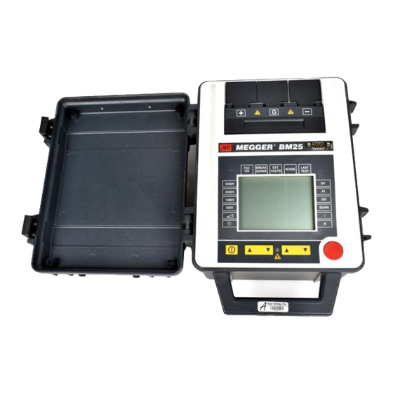
- Página 1 BM25 5 kV Digital Insulation Tester USER GUIDE GUIDE DE L’UTILISATEUR GEBRAUCHSANLEITUNG GUÍA DEL USUARIO...
-
Página 2: Tabla De Contenido
CONTENTS Guide de l’utilisateur - p30 Gebrauchsanleitung - s50 Guía del usuario - p70 Safety Warnings Specification General Description Accessories Test Mode Summary Appendix 1 - Results displayed at the end of each test Features and Controls Appendix 2 - RS 232 Output information display examples Battery Charging Repair and Warranty Operation... -
Página 3: Safety Warnings
The circuit under test must be switched off, de-energised and isolated before test connections are made. The BM25 can generate up to 2 mA at 5000 V. Circuit connections must not be touched when HV is selected. Circuits must be discharged before disconnecting the test leads. -
Página 4: General Description
Polarization Index, Step Voltage, and fuses are located in a splashproof protected recess in the front panel. Dielectric Discharge tests as well as spot Insulation tests. The BM25 has a Specially designed lid hinges enable the lid to be removed and replaced as resistance measurement capability up to 5 TΩ... -
Página 5: Test Mode Summary
TEST MODE SUMMARY Insulation Resistance Testing (R) Step Voltage Testing (SV) This mode measures insulation resistance at the selected voltage to This 5 minute test depends on the principle that an ideal insulator will provide an instantaneous spot reading. Final test result is given produce identical resistance readings at all voltages. -
Página 6: Features And Controls
FEATURES AND CONTROLS Splashproof recess Cover Slides Terminal Connection covers back to reveal mains and 12V battery Individually lifted to access test lead terminals. Covers interlocked with charging connections together with instrument protection fuses. sliding recess cover. RS232C socket Sends test results every 5 secs Voltage display to enable download to PC. -
Página 7: Battery Charging
BATTERY CHARGING Battery Charging Notes General Do not leave battery in a totally discharged state. Frequent It is advisable to fully charge the battery before the instrument is put into charging to keep the battery ‘topped up’ will maximise battery life. service for the first time. -
Página 8: Operation
Circuit connections must not be touched during a test. 12. If any part of the instrument is damaged, it should not be used, but The BM25 can give an electric shock. Highly capacitive circuits (e.g. returned to the manufacturer or an approved repair company. -
Página 9: Performing Tests - General
Start a test by pressing the red test button for at least 1 second. The flashing red LED and the flashing H.V . symbols warn that a test is Switch the BM25 On by pressing the ‘On/Off ’ switch once. All LCD in progress. -
Página 10: Testing Procedures
Start the test by pressing the red test button for at least one second. Polaristation Index (PI) of the sample. On completion, the final resistance measurement is displayed The BM25 is capable of carrying out the more generalised DAR test and sequentially with the corresponding leakage current and the the PI test automatically. -
Página 11: Dielectric Discharge Testing (Dd)
Accept the default voltage of 500 V , or using the L M Selector keys The BM25 is now set ready for performing the P .I. Test and at the end of move the left hand cursor to the required test voltage. -
Página 12: Step Voltage Testing (Sv)
Custom timed PI test This test is based on the principle that an ideal insulator will produce When new, the BM25 is set up with PI ratio is calculated on the time identical resistance readings at all voltages while an insulator which is settings of 1 minute (T1) and the 10 minute (T2) values. -
Página 13: Using The Guard Terminal
The information, see Appendix 1. BM25 is capable of measuring up to 5 TΩ, and down to 0,01 nA Using the Guard terminal (equivalent to 500 TΩ at 5000 V). When measuring resistances this high,... -
Página 14: Condition And Warning Indicators
OPERATION This sequential display repeats until a key is pressed or Auto EXT VOLTS switch-off operates. A flashing cursor below the ‘EXT VOLTS’ label combined with the flashing Note: In this mode, break-down of the circuit and the related noise LED on the front of the instrument, and the flashing high voltage symbols interference may cause the instrument to terminate the operation, indicates that the voltmeter is reading a hazardous voltage which... -
Página 15: Data Download
The RS232 socket is optically isolated from all other circuits within the In order to run, the software will require the command words BM25. It is therefore safe to connect a computer to this socket while tests BM25LOAD followed by 2 parameters. These parameters are: are being performed. - Página 16 At the end of a download, one or two files will have been created in the default or specified path location. These files can then be Set the required test settings and duration on the BM25. A test of imported into a variety of databases, spreadsheets or graph software 90 minutes duration will create a data file of approximately 43 KB.
-
Página 17: Application Notes
APPLICATION NOTES Preventive Maintenance The proverb ‘A stitch in time saves nine’ inspired the title of a Megger Limited booklet on insulation testing, as it neatly sums up the benefits of preventative maintenance. The savings come in financial terms from costly repairs, lost production, lost profits and in human terms, from lives saved in the event of dangerous electrical faults. -
Página 18: Insulation Testing Concepts
APPLICATION NOTES Insulation Testing Concepts A current flowing along conduction paths through the Insulation resistance can be considered by applying Ohm’s Law. The insulation material. measured resistance is determined from the applied voltage divided by the A current flowing along conduction paths over the surface resultant current, of the insulation material. -
Página 19: Application Of Test Techniques
The PI test also has the advantage of not requiring temperature correction. seconds and the BM25 will allow you to set this time and the test will The value of PI can give a rough guide to condition of insulation, although finish automatically. - Página 20 APPLICATION OF TEST TECHNIQUES The DD value is defined as:- during the discharge phase. Current flowing after 1 minute (mA) I1min The charge that is stored during the insulation test is automatically discharged at the end of the test when the discharge resistors are switched Test Voltage (V) x Capacitance (µF) V x C across the terminals.
-
Página 21: Stress Considerations
Stress Considerations Figure 3. shows a problem which can occur. If one end of the sample is Measurement above 100 GΩ grounded and this is required to be connected to the positive terminal, then the negative (measurement) lead is surrounded by a 5 kV field. This Figure 1. -
Página 22: Specification
SPECIFICATION Test Voltages (d.c.): 500 V , 1000 V , 2500 V & 5000 V . 50 – 5000 V variable in 25 V steps. Voltage Accuracy (0 °C to + 30 °C): ±2% ±1 V of nominal test voltages (load resistance >100 MΩ). ±25 V for test voltages <500 V Insulation Range: 100 kΩ... - Página 23 Leakage current range: 0,01 nA to 999 µA. Accuracy (0°C to +30°C): ±5% ±0,2 nA at all voltages. Capacitance range: 0,01 µF to 10,0 µF (measured with test voltages > 200 V). Accuracy (0°C to 30°C): ±15% ±0,03 µF. Hum Rejection: 1 mA rms per kV test voltage.
- Página 24 SPECIFICATION E.M.C: In accordance with IEC61326 including amendment No.1 Environmental protection: IP54 (with the charging recess cover securely closed). Temperature range: Operating: -20°C to +50°C (Errors double outside range 0˚C to 30°C). Storage: -25°C to +65°C. Humidity: 90˚ RH at 40˚C Altitude: 2000 metres maximum to operate within full specification.
-
Página 25: Accessories
HV Test lead set, 3 m long 6121-403 (210968) 9 way ‘D’ female to 9 way ‘D’ female connector lead, 1,8m long 25955-025 BM25 Download 31⁄2 inch diskette 6111-442 Accessory Pouch 6420-096 Mains (line) power cord Available as an optional extra... -
Página 26: Appendix 1 - Results Displayed At The End Of Each Test
APPENDIX 1 Results Displayed at end of each test PI Test IR Test Default test time of 10 minutes. Terminating the test prematurely still Default test time 30 minutes. allows the test results to be calculated and displayed. Timer Digital Indicator Voltage Indicator Other Timer... - Página 27 DD Test SV Test Default test time of 30 minutes, followed by a 1 minute discharge time. Test time set at 5 minutes only. Terminating the test prematurely may Terminating the test prematurely still allows the test results to be cause some results to be displayed as - - -.
-
Página 28: Appendix 2 - Rs 232 Output Information Display Examples
APPENDIX 2 RS 232 Output Information display examples Spreadsheet format example Heading Type of Test Leakage Extra columns at the end for specific Burn Burn DD test or PI test results. ASCII format example... -
Página 29: Repair And Warranty
A number of independent instrument repair companies have been instrument has been impaired it should not be used, and be sent for repair approved for repair work on most Megger instruments, using genuine by suitably trained and qualified personnel. The protection is likely to be Megger spare parts. - Página 30 TABLE DES MATERIÉRES GEBRAUCHSANLEITUNG - S50 GUÍA DEL USUARIO - P70 Avertissements de Sécurité Annexe 2 Description Générale Réparation et Garantie Récapitulatif du mode d’essai Fonctions et Commandes Recharge des accumulateurs Fonctionnement Précautions d’essai Réalisation des essais - généralités Procédure d’essai Test de Résistance de l’Isolation (R) Test de mesure du Courant (I) Test d’Indice de Polarisation (PI)
-
Página 31: Avertissements De Sécurité
Le circuit testé doit être débranché, mis hors tension et isolé avant d’effectuer les connexions de tests. Le BM25 peut produire jusqu’à 2 mA à 5000 V . Il ne faut pas toucher les connexions du système quand HV est sélectionné. -
Página 32: Description Générale
DESCRIPTION GÉNÉRALE Le BM25 est un instrument compact, à haute tension automatisé et segments affiche en continu la capacité des accumulateurs.Cet indicateur marchant sur piles, utilisé pour effectuer des tests d’Indice de Polarisation, clignote dès qu’il faut recharger les recharger. Cet appareil est en fait de Paliers de Tension et de Décharge Diélectrique ainsi que des test... -
Página 33: Récapitulatif Du Mode D'essai
RÉCAPITULATIF DU MODE D’ESSAI verrouiller dans le boîtier, afin d’empêcher tout débranchement du test est donné de façon séquentielle avec la valeur PI, la valeur finale accidentel. de résistance ainsi que la valeur de capacitance. Les valeurs DD de durée personnalisée peuvent être fixées si besoin est (voir ’Test DD à... -
Página 34: Fonctions Et Commandes
FONCTIONS ET COMMANDES Couvercle en creux à l’épreuve des Couvercles des connexions de éclaboussures - Faire coulisser ce bornes couvercle pour accéder aux branchements Chaque couvercle se soulève, ce qui secteur et aux connexions de recharge des permet d’accéder aux bornes des accumulateurs 12 V ainsi qu’aux fusibles de conducteurs d’essai. -
Página 35: Recharge Des Accumulateurs
RECHARGE DES ACCUMULATEURS Attention: l’emploi d’une tension supérieure à 15 V sur cette prise Généralités femelle provoque une recharge excessive de l’accu. Il est recommandé de bien charger les accus avant de mettre en route ces Remarques sur la recharge d’une accu: appareils pour la première fois. -
Página 36: Fonctionnement
Il ne faut pas toucher aux connexions de circuit pendant un essai. toute humidité (en particulier au niveau des prises femelles des Le BM25 peut donner un choc électrique. Les circuits à forte conducteurs d’essai). capacité (par exemple les cables de grand longuer) qui 11. -
Página 37: Réalisation Des Essais - Généralités
25 et 5000 V c.c. ou de modifier en continu cette tension par paliers de 25 V pendant le déroulement d’un essai. Pour effectuer une Mettez le BM25 sous tension en appuyant à une reprise sur le sélection, amenez le curseur gauche sur la position Tension variable bouton ’MARCHE/ARRET’. -
Página 38: Procédure D'essai
FONCTIONNEMENT Vous pouvez interrompre manuellement un essai, à tout moment, Lancez l’essai en appuyant sur le bouton d’essai rouge pendant au en appuyant sur le bouton d’essai rouge. Un essai s’interrompt moins 1 seconde. automatiquement si : Une fois les essais terminés, la mesure finale de résistance vient la durée programmée de l’essai est atteinte. -
Página 39: Test D'indice De Polarisation (Pi)
de plus amples reseignements sur les informations fournies par quantités d’impuretés et d’humidité absor. Ces paramètres implicites ont l’affichage final, consultez l’Annexe 1. une tension de 500 V et une durée de 30 minutes. Cependant, vous pouvez modifier ces paramètres en fonction de vos besoins. Les Test d’Indice de Polarisation (PI) paramètres implicites sont réinitialisés si vous placez le curseur de la Indice de Polarisation est un terme s’appliquant au rapport d’Absorption... -
Página 40: Essai À Paliers De Tension (Sv)
Test PI à Durée Personnalisée sur ’SV’. Lorsqu’il est neuf, le BM25 est installé avec un rapport PI calculé sur des réglages de durée de 1 minute (T1) et de 10 minutes (T2). La durée T3 Acceptez la durée implicite de test de 5 minutes. -
Página 41: Utilisation De La Borne De Protection
éliminer les effets dûs au courant de fuite Lors des essais d’isolement de base et lorsqu’il est fort peu probable que en surface. Le BM25 peut effectuer des mesures jusqu’à un maximum de des courants de fuite en surface n’affectent les mesures, il n’est pas 5 TΩ... -
Página 42: Conditionnement De La Défaillance (Claquage)
Fonctionnement éviter les points affûtés au niveau des connexions du conducteur d’essai Indicateurs de condition et d’avertissement afin de ne pas encourager une décharge à effet corona. Le fusible FS2 implanté dans le logement du chargeur protège le circuit de Conditionnement de la Défaillance (Claquage) protection contre les impédances faibles en empêchant toute application Le mode de claquage met hors circuit le détecteur de ’BREAKDOWN’... -
Página 43: Numéros D'erreurs
NOISE Si des parasites externes (normalement un courant de ronflement à 50 ou 60 Hz) sont excessifs (>2 mA à 5 kV), les essais en cours s’interrompent et le curseur sous l’étiquette ‘NOISE‘ se met à clignoter. LAST TEST Ce curseur clignote dès qu’un essai est terminé et dès que la séquence répétitive des résultats finaux a été... -
Página 44: Transfert De Données
Vous devez exécuter ce programme avant de mettre sous tension le BM25. Cela crée un répertoire appelé BM25 sur votre disque dur et recopie le programme sur votre lecteur, depuis la disquette, dans ce répertoire. Si Pour lancer le programme à partir de la commande C:\, vous souhaitez employer un lecteur de disquette autre que A, remplacez Tapez CD\BM25 puis appuyez sur <ENTRER>. - Página 45 Programmez tous les paramètres requis d’essai ainsi que la durée sur le BM25. Un essai de 90 minutes crée un fichier contenant Lorsque le logiciel tourne, la couleur à l’écran vire au bleu et un environ 43 ko de données. Un fichier standard de données a une écran d’acheminement de fichier apparaît.
-
Página 46: Annexe 1
ANNEXE 1 l’emplacement implicite ou spécifié. Vous pouvez importer ces Test PI fichiers dans différentes bases de données, sur des tableurs ou La durée implicite du test est de 10 minutes. Arrêtez le test dans divers logiciels à graphiques. Consultez pour cela l’Annexe 2. prématurément permet toutefois aux résultats du test d’être calculés et affichés. - Página 47 Test DD Test SV La durée implicite du test est de 30 minutes, suivie par une minute de La durée implicite du test est de 5 minutes seulement. Arrêter le test durée de décharge. Arrêter le test prématurément permet toutefois aux prématurément permet toutefois aux résultats du test d’être calculés et résultats du test d’être calculés et affichés.
- Página 48 ANNEXE 2 Exemples d’affichage d’informations transmises sur la sortie RS 232 Exemple de format de tableur Entête Type d’essai Fuite Colonnes supplémentaires à la Burn Burn fin pour résultats spécifiques de tests DD et PI. Exemple de format ASCII...
-
Página 49: Réparation Et Garantie
êté agréées pour faire des opérations de réparation sur la plupart des affectée de quelque maniére il ne doit pas être utilisé et doit être expeedié instruments Megger utilisant des pièces d’origine Megger. Consultez le pour réparation par du personnel convenablement formé et qualifié. La distributeur désigné... - Página 50 INHALT GUÍA DEL USUARIO - P70 Hinweise zur Betriebssicherheit Anhang 1 Allgemeine Beschreibung Anhang 2 Übersicht über die Testverfahren Reparaturen und Garantie Einrichtungen und Regler Laden der Batterie Betrieb Vorsichtsmaßnahmen beim Testen Durchführung von tests - Allgemeines Testverfahren Testen des Isolationswiderstands (R) Prüfstrommessung (I) Testen des Polarisationsindexs (PI) Testen der dielektrischen Entladung (DD) 59...
-
Página 51: Hinweise Zur Betriebssicherheit
Der zu testende Schaltkreis muß vor der Herstellung von Verbindungen abgeschaltet, energielos gemacht und isoliert werden. Das BM25 kann bei 5000 V bis zu 2 mA erzeugen. Die Schaltkreisverbindungen dürfen bei Auswahl von HV (Hochspannung) nicht berührt werden. Vor dem Trennen der Testkabel müssen die Schaltkreise entladen werden. -
Página 52: Allgemeine Beschreibung
Der Strom wird von zwei parallel geschalteten Bleisäurebatterien Spannungsstufen-, dielektrischen Entladungs- und Punktisolationstests. bezogen. Falls eine Batterie ausfällt (oder eine interne Das BM25 kann Widerstände bis 5 TΩ messen, die Kriechstrommessung Schutzsicherung durchbrennt), arbeitet das Instrument mit der anderen ermöglicht das Messen von Widerständen bis Batterie weiter. -
Página 53: Übersicht Über Die Testverfahren
ÜBERSICHT ÜBER DIE TESTVERFAHREN Testen des Isolationswiderstands (R) DD-Werte können bei Bedarf geändert werden (siehe ‘Benutzerspezifische Mit diesem Verfahren wird der Isolationswiderstand bei der gewählten Zeitwerte für den DD-Test’). Spannung zur sofortigen Anzeige eines Punktmeßwerts gemessen. Das Testen mit Spannungstufen (SV) endgültige Testergebnis wird sequentiell zusammen mit dem zugehörigen Dieser 5 Minuten dauernde Test unterliegt dem Prinzip, daß... -
Página 54: Einrichtungen Und Regler
EINRICHTUNGEN UND REGLER Anschlußklemmenabdeckungen Spritzwassergeschützte Können einzeln zwecks Zugang zu den vertiefungsabdeckung Testkabelanschlüssen angehoben werden. Zurückschiebbar für Zugang zu den Abdeckungen sind durch die Netzspannungs-anschlüssen, den verschiebbare ertiefungsabdeckung batterieladeansch- lüssen und den gegeneinander verriegelt. Schutzsicherungen. RS232C-Buchse Spannungsanzeige Sendet alle 5 Sekunden Testergeb- nisse Zeigt die Testspannung oder externe zur Weiterleitung an einen PC Spannung >50 V zusammen mit... -
Página 55: Laden Der Batterie
LADEN DER BATTERIE Allgemeines Hinweise zum Aufladen der Batterie Es empfiehlt sich, die Batterie vor dem ersten Einsatz des Instruments Belassen Sie die Batterie nicht in vollständig entladenem Zustand. vollständig aufzuladen. Das Aufladen erfolgt entweder mit externem Häufiges Aufladen bis zum vollen Ladezustandverlängert die Netzwechselstrom oder mit 12 Volt Gleichstrom. -
Página 56: Betrieb
Verbindungen der Schaltkreis energielos gemacht hergestellt werden. und das Instrument abgeschaltet werden. Das Instrument darf nur von entsprechend ausgebildeten und Das BM25 hat die Umweltschutzklassifizierung IP54, derzufolge die befähigten Personen eingesetzt werden. Abdeckung der Ladeanschlußvertiefung fest geschlossen ist. Aus Sicherheitsgründen (und zur Vermeidung unerwünschter Während eines Tests dürfen Schaltkreisverbindungen Nicht Berhürt... -
Página 57: Durchführung Von Tests - Allgemeines
Oberseite der Anzeige angegeben. Wenn das Instrument auf variable Spannung eingestellt ist, kann die Testart nicht geändert werden. Schalten Sie das BM25 durch einmaliges Drücken der Taste ’Ein/Aus’ ein. Daraufhin leuchten alle Flüssigkristallanzeigen 5 Sekunden lang auf, und Hinweis: Wenn die Spannung während eines Tests geändert wird, ändert sich anschließend wird 5 Sekunden langdas Wort ’CAL’... -
Página 58: Testverfahren
BETRIEB Sicherung FS2 durchbrennt; Beginnen Sie den Test, indem Sie die rote Testtaste min destens eine Sekunde lang gedrückt halten. eine interne Störung auftritt. Wenn der Test abgebrochen worden ist, wird der gerade getest ete Wenn der Test abgeschlossen ist, wird der letzte Widerstands Schaltkreis automatisch entladen. -
Página 59: Testen Des Polarisationsindexs (Pi)
die Informationen der abschlie ßendenAnzeige vgl. Anhang 1. sind 500 V und 30 Minuten, doch diese können bei Bedarf geändert werden. Die Einstellungen werden auf die Vorgaben zurückgestellt, wenn Testen des Polarisationsindexs (PI) die Anzeigemarke von der Position ’DD’ fortbewegt wird. An den zu Als Polarisationsindex wird die dielektrische Absorptionsrate bez eichnet, testenden Isolator wird, um einen stabilen Zustand zu erzielen, 30 Minuten wenn die Widerstandswerte nach 1 Minute und erneut nach 10 Minuten... -
Página 60: Testen Mit Spannungsstufen (Sv)
Setzen Sie die rechte Anzeigemarke mit den L M Bereichstasten auf Benutzerspezifische Zeitwerte für den PI-Test ‘SV’. Im Neuzustand berechnet das BM25 das PI-Verhältnis mit den nach 1 Bestätigen Sie die voreingestellte Standard-Testdauer von 5 Minuten. Minute (T1) und 10 Minuten (T2) gemessenen Werten. Diese ursprüngliche Einstellung produziert ein PI-Ergebnis basierend auf dem... -
Página 61: Verwendung Desableitanschlusses
Schut zdrahtanschluß nicht verwendet zu werden. Bei Kabeltests jedoch können zwischen dem Oberflächenkriechströmen verwendet werden. Das BM25 kann bis 5 TΩ blanken Kabel und dem Außenmantel aufgrund von Feuchtigkeit oder und bis zu 0,01 nA (gleichbedeutend mit 500 TΩ bei 5000 V) messen. -
Página 62: Störungszustand (Burn)
BETRIEB gemessen werden, dürfen die Testkabel sich nicht berühren oder mit abgeschaltet und anschließend zur Rückstellung der Anzeige wieder irgendwelchen anderen Gegenständen in Kontakt kommen, da dies zu eingeschaltet werden. Kriechstrompfaden führt. Außerdem sollten scharfe Spitzen an den Zustands- und Warnanzeigen Testkabelanschlüssen vermieden werden, da diese die Koronaentladung begünstigen könnten. -
Página 63: Datenübermittlung
Die RS232-Buchse ist optisch von allen anderen Schaltkreisen im Inneren Brummstrom von 50 oder 60 Hz) wird der Test abgebrochen, und die des BM25 isoliert, so daß während des Testbetriebs gefahrlos ein Marke unter der Aufschrift ’NOISE’ beginnt zu blinken. - Página 64 Wenn Sie also z.B. den Port COM1 Ihres PC verwenden, geben Sie nach dem Befehl BM25LOAD ein Leerzeichen und die Ziffer 1 ein. Das BM25 kann nun durch einmaliges Drücken des Ein- /Ausschalters eingeschaltet werden. Nach der Kalibrierungsprüfung Wenn Sie die Meßergebnisse im Tabellenkalkulationsformat speichern wird im Download-Fenster die Softwareversion angezeigt.
-
Página 65: Anhang 1
Geben Sie die erforderlichen Testeinstellungen und die Testdauer Hinweis: Ein Test kann zu jedem Zeitpunkt ohne Beeinträchtigung der auf dem BM25 ein. Ein 90 Minuten dauernder Test erstellt eine Datenübermittlung unterbrochen und gestartet werden. Wenn ein Test vor Datei von ungefähr 43 kB. Die Standarddatei hat ausreichend der eingestellten Dauer abgebrochen wird, können Sie durch Drücken der... - Página 66 ANHANG 1 PI-Test DD-Test Voreingestellte Testdauer 10 Minuten. Auch bei vorzeitigem Abbruch des Voreingestellte Testdauer 30 Minuten, gefolgt von einer einminütigen Tests können die Testergebnisse berechnet und angezeigt werden. Entladungszeit. Auch bei vorzeitigem Abbruch des Tests können die Testergebnisse noch berechnet und angezeigt werden. Zeituhr Digitalanzeige Spannungsanzeige...
- Página 67 SV-Test Testdauer auf nur 5 Minuten eingestellt. Bei vorzeitigem Abbruch können einige Ergebnisse als - - - angezeigt werden. Zeituhr Digitalanzeige Spannungsanzeige Testdauer Leer Abschließende Testspannung Spannung R (bei 1 Minute) 1,00 minute bei 1 Minute Spannung 2,00 minuten R (bei 2 Minuten) bei 2 Minuten Spannung 3,00 minuten...
-
Página 68: Anhang 2
ANHANG 2 Anzeigenmuster für RS232-Ausgangsinformationen Formatmuster für Tabellenkalkulation Titel Testtyp Leakage Zusätzliche Spalten an Ende für spezifische Burn Burn Ergebnisse des DD- oder PI-Tests. ASCII-Formatmuster... -
Página 69: Reparaturen Und Garantie
Das Instrument enthält statisch empfindliche Bauteile, weshalb die gedruckte Schaltung sorgfältig behandelt werden muß. Falls die Eine Reihe von Firmen sind für die Reparatur der meisten Megger- Schutzvorrichtungen eines Instruments beschädigt worden sind, sollte es lnstrumente unter Verwendung von Original Megger-Ersatzteilen nicht verwendet, sondern an eine geeignete Reparaturwerkstatt geschickt autorisiert. - Página 70 GUÍA DEL USUARIO Avisos de Seguridad Copiado de datos Descripción General Apéndice 1 Resumen de la Función de prueba Apéndice 2 Funciones y controles Reparacione y Garantia Carga de la batería Funcionamiento Precauciones de comprobación Ejecución de las prueba - Generalidades Procedimientos de prueba Comprobación de la resistencia de aislamiento (R)
-
Página 71: Avisos De Seguridad
El circuito bajo prueba debe ser desconectado, desenergizado y aislado antes de proceder a efectuar las conexiones de prueba. El BM25 es capaz de generar hasta 2 mA a 5000 V . Las conexiones de circuitos no deben tocarse cuando se selecciona HV (alto voltaje). -
Página 72: Descripción General
La alimentación se obtiene de dos acumuladores de plomo de aislamiento por zonas. El BM25 tiene una capacidad medidora de recargables y sellados conectados en paralelo. Si una de las dos baterías resistencia de hasta 5 TΩ... -
Página 73: Resumen De La Función De Prueba
RESUMEN DE LA FUNCIÓN DE PRUEBA Medición de corriente de prueba (I) valores de DD temporizados a medida del usuario pueden ser fijados, si se requiere (véase ’Prueba de DD temporizada a medida del usuario’ Esta función mide el aislamiento al voltaje seleccionado para aportar una en la página 80). -
Página 74: Funciones Y Controles
FUNCIONES Y CONTROLES Cubiertas de la conexión terminal Cubierta de rebajo a prueba de Se levantan individualmente para dar salpicaduras acceso a los terminales de los cables de Cae hacia atrás para revelar las conexiones prueba. Las cubiertas están enclavadas con de la red y de carga de la batería de 12 V cubiertas empotradas corredizas. -
Página 75: Carga De La Batería
CARGA DE LA BATERÍA General Notas sobre la carga de la batería Es aconsejable recargar totalmente la batería antes de poner el No deje la batería totalmente descargada. La carga frecuente para mantener la batería ‘en su tope’, potenciará la existencia de la instrumento en funcionamiento por primera vez. -
Página 76: Funcionamiento
El voltímetro y función de descarga automática del BM25 se verá 13. En el supuesto de que la toma del cable de alimentación no fuera como características extras de seguridad y no como sustituto de la del tipo adecuado para las salidas de sus toma orrientes, no utilice práctica normal sobre seguridad en el trabajo. -
Página 77: Ejecución De Las Prueba - Generalidades
Nota: Cuando no se este realizando una comprobación, (es decir en modo de capacitivas (hasta aproximadamente 1µF) la tensión de prue ba espera), el BM25 actúa como un voltímetro (50 V a 1000 V). aparecerá en unos segundos. La tensión de prueba se controla Asegúrese de que todos los cables de prueba están limpios y en buenas... -
Página 78: Procedimientos De Prueba Comprobación De La Resistencia De Aislamiento (R)
FUNCIONAMIENTO 10. Para apagar el instrumento, pulse una vez el botón On/Off. La final, véase Apéndice 1. desconexión automática ocurre transcurridos 10 minutos de Medición de corriente de prueba (I) inactividad en los modos ’R’ ’I’ y ’Burn’ y transcurridos 30 minutos Esta modalidad de prueba mide el aislamiento continuamente a la tensión de inactividad en los modos ’DD’, ’PI’... -
Página 79: Pruebas De Descarga Dieléctrica (Dd)
Usando las teclas de alcance s t, mueva el cursor derecho ’DD’. hasta ‘PI‘. Acepte el tiempo por exclusión de 30 minutos o, usando las Usando las teclas selectoras L M, mueva el cursor izquierdo hasta teclas selectoras L M, mueva el cursor izquierdo hasta la el voltaje de prueba requerido. -
Página 80: Ajustes De Fábrica
Prueba PI temporizada a medida del usuario Estos tiempos pueden ajustarse en cualquier orden, pero T1 debe ser el Cuando es nuevo, el BM25 se ajusta de acuerdo con una relación de PI más corto y T3 el más largo. -
Página 81: Display De Final De Resultados De Prueba
Apéndice 1. limpios y secos. El cable de protección puede utilizarse para eliminar los efectos de la fuga superficial, de ser necesario. El BM25 es capaz de medir Uso del terminal de protección hasta 5 TΩ y tan poco como 0,01 nA (equivalente a 500 TΩ a Para las pruebas básicas de aislamiento y cuando apenas exista la... -
Página 82: Indicadores De Condición Y Aviso
FUNCIONAMIENTO hasta que se pulse una tecla o funcione la desconexión automática. Voltios Ext Nota: En esta modalidad, la interrupción del circuito y la interferencia Un cursor parpadeante debajo de la etiqueta ‘EXT VOLTS’, combinado del ruido correspondiente, pueden hacer que el instrumento deje de con el LED parpadeante en la parte frontal del instrumento, y los símbolos funcionar, causando posiblemente una pérdida de visualización mientras el de alto voltaje parpadeantes, indica el voltímetro está... -
Página 83: Copiado De Datos
El enchufe RS232 está aislado ópticamente de todos los restantes circuitos A fin de funcionar, el software necesitará las palabras de instrucción del BM25. Por lo tanto, no hay peligro en conectar un ordenador a este BM25DOWNLOAD seguido de 2 parámetros. Estos parámetros son: enchufe mientras se esté... -
Página 84: Al Ejemplo De Archivo De Copiado - Opción Ascii
Regule los ajustes de prueba necesarios y la duración en el BM25. vía implícito o específico. Estos ficheros pueden importarse entonces a Una prueba de 90 minutos de duración creará un archivo de datos diferentes bases de datos, hojas electrónicas o paquetes de software de... -
Página 85: Apéndice 1
APÉNDICE 1 Resultados visualizados al final de cada prueba Prueba PI Tiempo de prueba por exclusión de 10 minutos. La terminación prematura Prueba IR de la prueba todavía permite calcular y visualizar los resultados de la prueba. Tiempo de prueba por exclusión de 30 minutos. Temporizador Indicador digital Indicador de voltaje... - Página 86 APÉNDICE 1 Prueba DD Prueba SV Tiempo de prueba por exclusión de 30 minutos, seguido de un tiempo de El tiempo de prueba ajustado a 5 minutos solamente. La terminación descarga de 1 minuto. La terminación prematura de la prueba todavía prematura de la prueba puede causar la visualización de ciertos resultados permite calcular y visualizar los resultados de la prueba.
-
Página 87: Apéndice 2
APÉNDICE 2 Ejemplos de la representación de información de salida RS232 Ejemplo de formato de hoja eléctrica Encabezamiento Tipo de prueba Columnas adicionales al final para Fuite resultados específicos de la prueba DD Burn Burn o de la prueba PI Ejemplo de formato ASCII... -
Página 88: Reparacione Y Garantia
Reparación de Instrumentos y Piezas de Repuesto Para un servicio de los instrumentos Megger contacte por favor con: Megger Limited Megger Archcliffe Road... - Página 91 E ausales@megger.com F +1 416 298 0848 E casales@megger.com Megger products are distributed in 146 countries worldwide. This instrument is manufactured in the United Kingdom. The company reserves the right to change the specification or design without prior notice. Megger is a registered trademark Part No.