Tabla de contenido
Publicidad
Idiomas disponibles
Idiomas disponibles
Enlaces rápidos
AVO INTERNATIONAL
Archcliffe Road
Dover
Kent, CT17 9EN.
England.
Tel: +44 (0) 1304 502100
Fax: +44 (0) 1304 207342
This instrument is manufactured in the United Kingdom.
The company reserves the right to change the specification or design without prior notice.
MEGGER is the registered Trade Mark of AVO INTERNATIONAL LIMITED. Copyright ©, AVO INTERNATIONAL LIMITED
Part No 6172-697 - Edition 1 - Printed in England - 06FF
PO Box 9007
4271 Bronze Way
Valley Forge
Dallas
PA 19484-9007
TX 75237-1017
U.S.A.
U.S.A.
Tel: +1 (610) 676-8500
Tel: +1 (800) 723-2861 (U.S.A. only)
Fax: +1 (610) 676-8610
Tel: +1 (214) 330-3203 (International)
MEGGER SARL
29 Allée de Villemomble
93340 Le Raincy
Paris, France
Tel: +33 (1) 43.02.37.54
Fax: +33 (1) 43.02.16.24
Publicidad
Capítulos
Tabla de contenido

Manuales relacionados para Megger BMM500 Serie


Resumen de contenidos para Megger BMM500 Serie
- Página 1 The company reserves the right to change the specification or design without prior notice. MEGGER is the registered Trade Mark of AVO INTERNATIONAL LIMITED. Copyright ©, AVO INTERNATIONAL LIMITED Part No 6172-697 - Edition 1 - Printed in England - 06FF...
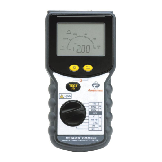
- Página 2 INSULATION & CONTINUITY TESTERS MEGGER ® BMM500 SERIES User Guide MEGGER ® Guide d’Utilisateur Benutzeranleitung Guía del Usuario...
-
Página 4: Tabla De Contenido
Voltage Tests (V) current EU Directives. Battery Replacement Equipment must not be Fuse Checking and Replacement >600V connected to voltage sources Using the MEGGER SP1 >600V CAT II. Suitable for Switched Probe electrical installations CAT III Specification 300V to Earth... -
Página 5: Safety Warnings
SAFETY WARNINGS • Safety Warnings and Precautions must be read and understood before the instrument is used. They must be observed during use. • The circuit under test must be de-energised and isolated before connections are made except for voltage measurement. •... -
Página 6: Description
A customised connector on the top of the The MEGGER BMM500 Series instruments instrument enables the optional MEGGER SP1 are battery powered Insulation and Continuity Switched Probe to be used for two handed testers, with a measurement capability from probe operation. -
Página 7: Operation
Operation Refer to Safety Warnings before using systems. Fused test leads are available as the instrument optional accessories for local situations where increased protection is required. Testing is automatically inhibited if: • An external voltage >55V is present when Auto-shut Off switched to any insulation range position To conserve battery life, Auto-shut Off •... -
Página 8: Insulation Tests
Operation alternatively the key can be re-pressed. 6. Remove the test leads only when no voltage is indicated. Insulation Tests (MΩ) (See fig. 1) The insulation tests apply a known voltage to Locking Test Button (ltb) the circuit under test and measure the resulting When it is desired to do a long insulation test, leakage current. -
Página 9: Automatic Discharge
Operation indicated on the display so that the discharge can be monitored. Typical Terminal Voltage Characteristics 1100 1000V 1000 500V 250V Fig.1 0.01 1000 on PI Testing and value assessment can be RESISTANCE (MΩ) found in AVO International publications listed in the Accessories page. -
Página 10: Zeroing Of Test Lead Resistance
Operation the reading will hold for a few seconds and then Zeroing of Test Lead Resistance The resistance of the test leads can be nulled reset. This range is not suitable for diode testing since the automatic contact detector will on the continuity range (up to 9,99Ω). -
Página 11: Continuity Bleeper
Operation Resistance Tests (kΩ) Continuity Bleeper This is a low voltage (5V) low current (25µA) The continuity bleeper sounds continuously test for sensitive electronic equipment. It when a resistance below the threshold level is detected. This can be selected from several operates in the same way as the continuity values between 2Ω... -
Página 12: Voltage Tests (V)
Operation current and wide measurement range(0,01kΩ 4. After a short settle time, the reading will to 10000kΩ) make the resistance range very be displayed automatically. useful for general purpose testing. Measuring Other Parameters Voltage Tests (V) The BMM500 Series can be used to measure If >1V a.c. -
Página 13: Battery Replacement
Operation 1. Select the d.c. mV range. instrument is not going to be used for an 2. Short the test leads together. extended period of time. 3. When the reading has stabilised, press the TEST button. The zero offset symbol The BMM500 Series incorporates an electronic will appear. -
Página 14: Using The Megger Sp1 Switched Probe
Operation Using the MEGGER SP1 Switched Probe Operation: The Megger SP1 is an accessory for designated Megger installation test instruments. When fitted in the specially designed connector, in place of the existing ‘Low’ lead, the SP1 acts as a remote test button to operate the instrument and as a ‘Low’... -
Página 15: Specification
Specification (All quoted accuracies are at +20°C.) Insulation Ranges Nominal Test Voltage (d.c.): 250V, 500V, 1000V Test voltage accuracy: +15% maximum on open circuit Short circuit current: < 2 mA Test Current on load: 1mA at min. pass value of insulation specified in BS7671, HD384 and IEC364, 2mA max. - Página 16 Specification Continuity Measuring Range: 0,01Ω to 99,9Ω (0-10Ω on analogue scale) EN61557 Operating range: 0,10Ω to 99,9Ω Accuracy: ±2% ±2 digits Open circuit voltage: 5V ±1V Test current: 210mA ±10mA (0-2Ω) Zero offset at probe tips: 0,10Ω typical Lead resistance zeroing: Up to 9,99Ω...
- Página 17 Specification Voltage Measuring Range: ±1V to ±600V (0 to 1000V on analogue scale) Accuracy: 0-600V d.c. ±2% ±3 digit 0-600V a.c (50/60Hz) ±2% ±3 digits 0-600V 400Hz a.c. ±5% ±3 digits Input resistance: approx 200kΩ. Detector Threshold: Millivolts Measuring Range: ±0,1mV to ±1999mV (0 to 1000mV on analogue scale) Accuracy:...
- Página 18 Specification Basic and service errors for Insulation and Insulation Resistance – MΩ Resistance ranges Limit Min. Limit Min. The basic error is the maximum inaccuracy of Indicated Indicated the instrument under ideal conditions, whereas Reading Reading the service error is the maximum inaccuracy 0,10 0,14 2,00...
- Página 19 Specification * Relates to the transient overvoltages likely to Continuity Resistance – Ω be met in fixed wiring installations. Limit Min. Limit Min. Complies with the following parts of EN61557, Indicated Indicated Electrical safety in low voltage systems up to Reading Reading 1000V a.c.
-
Página 20: Power Supply
Specification POWER SUPPLY Storage temperature range: -30 to +70°C Battery Type: 6x1,5V Alkaline Calibration Temperature: +20ºC cells IEC LR6 type Maximum altitude: 2000 m or 1.2V NiCd or Dust and water protection: IP54 NiMH Temperature coefficient: <0,1% per °C re-chargeable cells. - Página 21 Specification Specification ACCESSORIES Supplied: Part Number Test lead set 6220-437 Pouch 6172-124 Switch Test Probe 6220-606 (NA Version only) Optional: Fused lead set, FPK8 6111-218 Switch Test Probe SP1 6220-606 Test Record Cards (Pack of 20) 6111-216 Publications: ‘A Stitch in Time’ AVTM21-P8B ‘Testing Electrical Installations’...
-
Página 22: Repair And Warranty
Repair and Warranty The instrument circuit contains static sensitive Instrument Repair and Spare Parts devices, and care must be taken in handling For service requirements for MEGGER ® the printed circuit board. If the protection of an Instruments contact:- instrument has been impaired it should not be... - Página 23 Repair and Warranty Approved Repair Companies A number of independent instrument repair companies have been approved for repair work on most MEGGER ® instruments, using genuine MEGGER ® spare parts. Consult the Appointed Distributor / Agent regarding spare parts, repair facilities and advice on the best course of action to take.
-
Página 24: 600V
Fonctionnement Remplacement de la batterie Avertissement de circuit sous tension Vérification et remplacement du fusible Tests de tension sur des systèmes Utiliser la sonde à commutateur MEGGER SP1 31 à haute énergie Specifications Arrêt automatique Fond éclairé Reparations et Garantie Tests d’isolation (MΩ) -
Página 25: Avertissements Sur La Securite
AVERTISSEMENTS DE SECURITE Les avertissements et précautions de sécurité doivent être lues et comprises avant que l’instrument soit utilisé. Ils • doivent être suivis pendant l’utilisation. L’alimentation du circuit testé doit être coupée et il doit être isolé avant que les connexions soient faites, sauf pour les •... -
Página 26: Description Generale
Félicitations pour votre achat d’un véritable testeur Megger gamme de transducteurs pour développer davantage les d’isolement et de continuité. Megger a plus de 100 ans capacités des instruments de la série BMM, par exemple d’expérience des tests d’isolements, ce qui se répercute les mesures de température ou d’humidité. -
Página 27: Fonctionnement
Fonctionnement Se reporter aux avertissements de sécurité Avertissement de circuit sous tension avant d’utiliser l’instrument. Lorsque l’on applique plus de 25V aux bornes dans les Les tests sont automatiquement bloqués si: gammes d’isolation, l’instrument devient par défaut un Une tension externe >55V est présente lorsque voltmètre et émet un avertissement sonore si un test est l’équipement est mis dans toute position de la tenté. -
Página 28: Fond Éclairé
Fonctionnement prolongée de 60 minutes. Pour rallumer après un Arrêt Appuyer sur le bouton TEST pour activer la tension automatique, sélectionner ARRET suivi de la position du de test, relever la mesure lue. commutateur nécessaire. Relâcher le bouton de TEST à la fin du test. La dernière lecture restera sur l’écran. -
Página 29: Tests De L'indice De Polarisation
Fonctionnement Tests de l’indice de polarisation d’isolation (ou renfoncé si la fonction ltb est activée), une charge de 200kΩ est automatiquement transférée à travers L’indice de polarisation (IP) est un terme appliqué au rapport les bornes pour décharger l’élément sous test. Toute d’absorption diélectrique lorsque les valeurs de résistance tension présente sera indiquée sur l’écran de sorte que le sont mesurées après 1 minute puis de nouveau après 10... -
Página 30: Tests De Continuité (Ω)
Fonctionnement Tests de continuité (Ω) (voir fig.2) conducteur en utilisant les poussoirs. Lorsque la lecture sera stabilisée, appuyer sur le Les tests de continuité sont activés lorsque les sondes bouton de TEST. Le symbole de compensation à entrent en contact à moins de quelques kΩ. Le test zéro va apparaître. -
Página 31: Sources Possibles D'erreur
Fonctionnement Sources possibles d’erreur Tests de résistance (kΩ) Les mesures et les résultats peuvent être affectés par: C’est un test à basse tension (5V) et à basse intensité • L’impédance de circuits en fonctionnement (25µA) pour un équipement électronique sensible. Il connectés en parallèle fonctionne de la même manière que les gammes de •... -
Página 32: Tests De Tension (V)
Fonctionnement Tests de tension (V) Connecter les fils de tests. Après un bref instant de mise au point, la lecture Si un courant alternatif ou continu de >1V est observé aux apparaîtra automatiquement. bornes, la tension mesurée est indiquée sur l’écran. L’affichage de tension fonctionnera conformément aux Mesurer d’autres paramètres spécifications même si le fusible grille. -
Página 33: Remplacement De La Batterie
Fonctionnement la gamme de mV en courant continu. Le symbole Remplacement de la batterie apparaîtra pour indiquer que le zéro a été réglé. Lorsqu’un symbole de batterie à plat apparaît, les piles Sélectionner la gamme de mV en courant continu. sont presque épuisées et devront être remplacées dès que Raccorder les fils de tests ensemble. -
Página 34: Vérification Et Remplacement Du Fusible
à deux mains. La SP1 convient à l’utilisation avec les instruments de tests d’isolation MEGGER jusqu’à 1KV de tension de test de sortie. Sécurité: Elle répond aux exigences de sécurité pour la... -
Página 35: Specifications
Specifications (Toutes les précisions indiquées sont à +20°C.) Gammes d’isolation Nominal Test Voltage(d.c.): 250V, 500V, 1000V Précision de tension de test: +15% maximum sur un circuit ouvert Intensité de court circuit: < 2 mA Intensité de test au chargement: 1mA à la valeur de passage mini. d’isolation définie dans les normes BS7671, HD384 et IEC 364, 2mA maxi. - Página 36 Specifications Précision: ±2% ±2 chiffres Tension de circuit ouvert: 5V ±1V Intensité de test : 210mA ±10mA (de 0 à 2Ω) Compensation du zéro aux sondes: 0,10Ω en général Mise à zéro de la résistance des fils: Jusqu’à 9,99Ω Rejet de bruit : 1V rms 50/60Hz Alarme : Sélectionnable –...
- Página 37 Specifications Millivolts Gamme de mesures: de ±0,1mV à ±1999mV (de 0 à 1000mV sur l’échelle analogique) Précision: 0,1mV à 10mV c.c. ou c.a. (50/60 Hz) ±2% ±5 chiffres 10mV à 1999mV c.c. ou c.a. (50/60 Hz) ±2% ±3 chiffres 0,1mV à 10mV c.a. (16-460 Hz) ±5% ±7 chiffres 10mV à...
- Página 38 Specifications Resistance de continuité – Ω Resistance d’isolation – MΩ Limite Lecture Limite Lecture Limite Lecture maxi. Limite Lecture maxi. mini. indiquée mini. indiquée indiquée indiquée 0,10 0,06 2,00 1,88 0,10 0,14 2,00 2,12 0,20 0,15 3,00 2,84 0,20 0,25 3,00 3,16 0,30...
-
Página 39: Alimentation Electrique
Specifications SECURITE FUSIBLE 500mA (F) 500V, 32x 6mm Céramique HBC 10kA L’instrument répond aux exigences de sécurité pour la minimum. double isolation conformément aux normes IEC1010-2-031 (1995), EN61010-2-031 (1995), Catégorie III*, de 300V de C.E.M. la phase à la terre et de 440V de phase à phase, sans L’instrument est conforme aux normes EN 50081-1 et EN besoin de fils de tests à... -
Página 40: Conditions Environnementales
Specifications CONDITIONS ENVIRONNEMENTALES ACCESSOIRES Fourchette de fonctionnement de -5 à +40°C Fourni: Humidité de fonctionnement 90% d’humidité relative Numéro de pièce à 40°C maxi. Jeu de fils de tests Fourchette de températures 6220-437 de Stockage de -25 à +65°C Mallette de tests portable- Température de réglage +20°C Altitude maximale... -
Página 41: Reparations Et Garantie
MEGGER ® , à l’aide de pièces détachées MEGGER ® véritables. Se reporter à la liste des Distributeurs/Agents désignés concernant les pièces détachées, les équipements de réparations et des recommandations sur la... - Página 42 Reparations et Garantie Renvoyer un instrument pour réparation Si vous renvoyez un instrument au fabricant pour des réparations, il doit être envoyé en port payé à l’adresse qui convient. Une copie de la facture et de la note d’emballage doivent être envoyées en même temps par poste par avion afin d’expédier le dédouanement aux Douanes.
- Página 43 Inhaltsverzeichnis Sicherheitshinweise Verwenden der Geschalteten Sonde MEGGER SP1 Allgemeine Beschreibung Technische Daten Bedienung Warnung bei stromführenden Stromkreisen Reparator und Garantie Spannungsprüfung bei Hochenergieanlagen Automatisches Ausschalten Hintergrundbeleuchtung Isolationsprüfungen (MΩ) Einrastende Prüftaste (ltb) Auf dem Gerät werden die folgenden Symbole Prüfung des Polarisationsindex...
-
Página 44: Sicherheitshinweise
SICHERHEITSHINWEISE Die Sicherheitshinweise und Vorsichtsmaßnahmen müssen gelesen und verstanden werden, bevor das Gerät benutzt wird. • Sie müssen während des Gebrauchs befolgt werden.. Der zu prüfende Stromkreis muß, außer für die Spannungsmessung, stromlos geschaltet und abgetrennt werden, bevor die • Anschlüsse hergestellt werden. -
Página 45: Allgemeine Beschreibung
Ein speziell angefertigter Stecker oben am Gerät Anforderungen des Benutzers zu erfüllen und seine Arbeit ermöglicht die Verwendung der als Sonderzubehör zu unterstützen. erhältlichen geschalteten Sonde MEGGER SP1 für die Die Geräte der Reihe MEGGER BMM500 sind zweihändigen Bedienung der Sonde. batteriebetriebene Isolations- und Durchgangsprüfgeräte Die Bereiche 250V, 500V und 1000V können zum Prüfen... -
Página 46: Bedienung
Bedienung Lesen Sie die Sicherheitshinweise, bevor Sie das 30V messen, insbesondere in Hochenergieanlagen. Gerät benutzen. Abgesicherte Prüfkabel sind für örtliche Situationen, in denen erhöhter Schutz benötigt wird, als Sonderzubehör erhältlich. Die Prüfung wird automatisch verhindert, wenn: Eine externe Spannung von >55V anliegt, wenn das Automatisches Ausschalten Gerät in eine beliebige Isolationsbereichstellung Zum Schonen der Batterie schaltet das Gerät (nachdem... -
Página 47: Isolationsprüfungen (Mω)
Bedienung XXXXX auch nochmals gedrückt werden. erscheint die Spannungswarnung, und die vorhandene Spannung wird angezeigt. Isolationsprüfungen (MΩ) (Siehe Abb.1) Entfernen Sie die Prüfkabel erst, wenn keine Spannung mehr angezeigt wird. Bei den Isolationsprüfungen wird eine bekannte Spannung an den zu prüfenden Stromkreis angelegt und der daraus Einrastende Prüftaste (ltb) resultierende Kriechstrom gemessen. -
Página 48: Automatische Entladung
Bedienung Widerstandswert nach 10 TYPISCHE EIGENSCHAFTEN DER Minuten geteilt durch den ANSCHLUßSPANNUNG Widerstandswert nach 1 Minute. Die Prüfung kann bei 1100 1000V beliebiger Spannung 1000 ausgeführt werden. finden ausführlichere Angaben zur PI-Prüfung und Bewertung 500V Ergebnisse in den auf der Zubehörseite aufgeführten 250V Veröffentlichungen von AVO... -
Página 49: Nullen Des Prüfkabelwiderstands
Bedienung Nullen des Prüfkabelwiderstands Der Widerstand der Prüfkabel kann im Durchgangsbereich (bis 9,99Ω) genullt werden. Die Nullinformation wird in einem nichtflüchtigen Speicher gespeichert und bleibt so erhalten, wenn das Gerät ausgeschaltet wird. Wählen Sie den Durchgangsbereich. Schlieflen Sie die Prüfkabel mittels Prüfspitzen über eine bekannten guten Leiter kurz. -
Página 50: Durchgangspiepser
Bedienung Durchgangspiepser Der Widerstandsbereich wird durch eine Methode mit Der Dauer-Piepser ertönt ununterbrochen, wenn ein hoher Impedanz geschützt. Wenn daher das Gerät an Widerstand unter der Grenzstufe aufgespürt wird. einen stromführenden Stromkreis angeschlossen wird, Dieser kann aus einer Reihe von Werten zwischen löst die Sicherung nicht aus, wie bei den Isolations-, 2Ω... -
Página 51: Millivoltprüfungen (Mv)
Bedienung Sie es an einer bekannten Quelle überprüfen. Ausgabemassstab von 1mV/ºC wird auf der Anzeige direkt Stellen Sie den Wahlschalter in die Stellung V. in ºC umgesetzt. Schließen Sie die Prüfkabel an. Bestimmte Sonden, wie z.B. Windgeschwindigkeitsmesser, Nach einer kurzen Beruhigungszeit wird das müssen auf Null gesetzt werden. -
Página 52: Ersetzen Der Batterie
Abdeckung des Batteriefachs wieder an, und befestigen Sie sie. Nehmen Sie die Zellen heraus, wenn das Gerät während Bedienung: Die Sonde MEGGER SP1 ist ein Zubehörteil für längerer Zeit nicht benutzt werden wird. als solche bezeichnete Installationsprüfgeräte von MEGGER. - Página 53 Bedienung Sicherheit: Erfüllt die Sicherheitsanforderungen für Doppelisolation nach IEC1010-2-031 (1995), EN61010-2- 031 (1995), IEC1010-1 (1995), EN61010-1 (1995) Kategorie III*, 300V Phase gegen Erde und 500V Phase gegen Phase. Die Sonde ist mit einer internen, nicht ersetzbaren Sicherung ausgestattet, die den Benutzer schützt, falls die Sonde aus Versehen in Verbindung mit einem Prüfkabel in der niedrigen Klemme benutzt wird.
-
Página 54: Technische Daten
Technische Daten (Alle Genauigkeiten sind für +20°C angegeben.) Isolationsbereich Nennprüfspannung (Gleichstrom): 250V, 500V, 1000V Genauigkeit der Prüfspannung: +15% maximal bei offenem Stromkreis Kurzschlußstrom : < 2 mA Prüfstrom unter Last: 1mA bei min. Durchgangswert der Isolation gemäß BS7671, HD384 und IEC 364, max. 2mA. - Página 55 Technische Daten Nullpunktverschiebung bei Sonden: typischerweise 0,10Ω Nullen des Kabelwiderstands: Bis zu 9,99Ω Rauschunterdrückung: 1V Wirkspannung 50/60Hz Summer: Wählbar - Betrieb bei weniger als 2Ω, 5Ω, 20Ω, 50Ω, 200Ω, 500Ω, 3kΩ (ca.). Widerstand Meflbereich: 0,01kΩ bis 9,99MΩ (0 bis 100MΩ auf Analogskala) Genauigkeit: ±3% ±2 Ziffern Spannung bei offenem Stromkreis: 5V ±1V...
- Página 56 Technische Daten Millivolt Meflbereich: ±0,1mV bis ±1999mV (0 bis 1000mV auf Analogskala Genauigkeit: 0,1mV bis 10mV d.c. bzw. a.c. (50/60Hz) ±2% ±5 Ziffern 10mV bis 1999mV d.c. bzw. a.c. (50/60 Hz) ±2% ±3 Ziffern 0,1mV bis 10mV a.c. (16-460 Hz) ±5% ±7 Ziffern 10mV bis 1999mV a.c.
- Página 57 Technische Daten Durchgangswiderstand – Ω Isolationswiderstand – MΩ Grenze Min. Grenze Min. Grenze Min. Grenze Min. angezeigter angezeigter angezeigter angezeigter Ablesewert Ablesewert Ablesewert Ablesewert 0,10 0,14 2,00 2,12 0,10 0,06 2,00 1,88 0,20 0,25 3,00 3,16 0,20 0,15 3,00 2,84 0,30 0,35 4,00...
- Página 58 Technische Daten SICHERHEIT E.M.V. Die Geräte erfüllen die Anforderungen für Doppelisolation Die Geräte entsprechen EN 50081-1 und EN 50082-1 nach IEC 1010-1 (1995), EN 61010-1 (1995) für Kategorie (1992). III*, 300V Phase gegen Erde (Masse) und 440V Phase STROMVERSORGUNG gegen Phase, ohne Notwendigkeit getrennt abgesicherter Batterietyp: 6x1,5V Alkalizellen Typ Prüfkabel.
- Página 59 Technische Daten Temperaturkoeffizient <0,1% pro °C GEWICHT 742g ABMESSUNGEN 110mm x 220mm x 45mm REINIGUNG Mit einem sauberen, mit Seifenwasser oder Isopropylalkohol befeuchteten Tuch abwischen ZUBEHÖR Mitgeliefert: Teilenummer Prüfkabelsatz 6220-437 Prüf- & Tragekoffer - Sonderzubehör: Teilenummer Abgesicherter Kabelsatz, FPK8 6111-218 Geschaltete Prüfsonde SP1 6220-606 Prüfprotokollkarten...
-
Página 60: Reparator Und Garantie
Datum des Kaufs durch den Benutzer. or an approved repair company. Hinweis: Jede vorherige unberechtigte Reparatur bzw. Anerkannte Reparaturbetriebe Anpassung macht die Garantie automatisch ungültig. Eine Reihe unabhängiger Gerätereparaturbetriebe wurden für die Reparatur der meisten MEGGER ® -Geräte anerkannt und verwenden echte MEGGER ® -Ersatzteile. - Página 61 Reparatur und Garantie Einschicken eines Geräts zur Reparatur Wenn Sie ein Gerät zur Reparatur an den Hersteller zurückschicken, muß es mit vorausbezahltem Porto an die entsprechende Adresse geschickt werden. Eine Kopie der Rechnung und des Lieferscheins sind gleichzeitig mit Luftpost zu schicken, um die Zollabfertigung zu beschleunigen.
- Página 62 Aviso de circuito activo Verificación y recambio de fusibles Pruebas de voltaje en sistemas de alta energía 62 Para usar la función de la sonda Desconexión automática conmutada MEGGER SP1: Luz posterior Especificaciones Pruebas de aislamiento (MΩ) Bloqueo del botón de prueba (ltb) Reparacion y Garantia Prueba del índice de polarización...
-
Página 63: Avisos De Seguridad
AVISOS DE SEGURIDAD Antes de usar el instrumento deberán leerse y comprenderse las precauciones y los avisos de seguridad • pertinentes. Deberán ser observados durante el uso. El circuito en prueba debe ser desenergizado y aislado antes de efectuar las conexiones, exceptuando la medición •... -
Página 64: Description General
Megger auténtico. La firma de instalar una amplia variedad de transductores para Megger posee más de 100 años de experiencia en la realzar todavía más las capacidades de los instrumentos verificación del aislamiento, lo cual se refleja en los diseños de la Serie BMM, como por ejemplo las mediciones de de sus productos. -
Página 65: Funcionamiento
Funcionamiento Consulte los avisos de seguridad antes de usar el superiores a 30V, particularmente en sistemas de alta instrumento. energía. Los conductores de prueba con fusible se ofrecen disponibles como accesorios opcionales para aplicaciones Las pruebas son inhibidas automáticamente si: locales en las que se requiere una mayor protección. -
Página 66: Pruebas De Aislamiento (Mω)
Funcionamiento automáticamente para conservar la vida útil de la batería, Retire los conductores de prueba sólo cuando no haya ningún voltaje visualizado. o bien puede pulsarse de nuevo la tecla XXXXX. Bloqueo del botón de prueba (ltb) Pruebas de aislamiento (MΩ) (vea la figura 1) Si es preciso realizar una prueba de aislamiento, ésta puede Las pruebas de aislamiento aplican a un voltaje conocido ∼... -
Página 67: Descarga Automática
Funcionamiento valores de resistencia son medidos después de 1 minuto y CARACTERÍSTICAS TÍPICAS DEL VOLTAJE DE de nuevo después de 10 minutos. El índice de polarización BORNES es así pues el valor de resistencia después de 10 minutos dividido por el valor de resistencia después de 1 minuto. La 1100 prueba puede realizarse a cualquier voltaje. -
Página 68: Puesta A Cero De La Resistencia Del Conductor De Prueba
Funcionamiento Puesta a cero de la resistencia del conductor de prueba La resistencia de los conductores de prueba puede ser anulada en el rango de continuidad (hasta 9,99Ω). La información anulada es retenida en una memoria involátil y por ello será recordada cuando se apaga el instrumento. Seleccione el rango de continuidad. -
Página 69: Emisor De Pitidos De Continuidad
Funcionamiento Emisor de pitidos de continuidad El rango de resistencia está protegido mediante un sistema de alta impedancia y por consiguiente, si el instrumento es El localizador de continuidad suena continumente cuando conectado a un circuito activo, el fusible no se quemará se detecta una resistencia inferior al nivel del umbral. -
Página 70: Pruebas De Milivoltios (Mv)
Funcionamiento funcionamiento del voltímetro, pruebe voltímetro en una temperatura y corriente hasta la velocidad del viento, fuente conocida. mediante el uso de cabezales medidores de salida en Sitúe el interruptor selector en V. mV. Podrá ser utilizado cualquier cabezal medidor Conecte los conductores de prueba. -
Página 71: Recambio De Pilas
Asegure que las pilas de repuesto sean instaladas con la polaridad correcta de acuerdo con la Para usar la función de la sonda conmutada MEGGER SP1: etiqueta incluida en el alojamiento de la batería. Vuelva a El MEGGER SP1 es un accesorio para uso con conectar el soporte de la batería a los conductores de ésta. - Página 72 Funcionamiento Seguridad: Satisface los requerimientos de seguridad de aislamiento doble según las IEC1010-2-031 (1995), EN61010-2-031 (1995), IEC1010-1 (1995), EN61010-1 (1995) Categoría III*, 300V de fase a tierra y 500V de fase a fase. La sonda está provista de un fusible interno, no recambiable, para proteger al usuario, si la sonda se usa por descuido en conjunción con una conductor de prueba en el borne bajo.
-
Página 73: Especificaciones
Especificaciones (Todas las precisiones se indican a +20°C.) Rango de aislamientos Prueba nominal: 250V, 500V, 1000V Precisión de voltaje de prueba: +15% máximo en circuito abierto Corriente de cortocircuito: <2mA Corriente de prueba en carga: 1mA a valor de aislamiento de paso mínimo especificado en BS7671, HD384 y IEC 364, 2mA máximo. - Página 74 Especificaciones Precisión: ±2% ±2 dígitos Voltaje en circuito abierto: 5V ±1V Corriente de prueba: 210mA ±10mA (0-2Ω) Desviación cero en las sondas: 0,10Ω típica Puesta a cero del resistencia de conductor: Hasta 9,99Ω Rechazo de ruidos: 1V rms 50/60Hz Zumbador: Seleccionable –...
- Página 75 Especificaciones Milivoltios Rango de medición: ±0,1mV a ±1999mV (0 a 1000mV en escala analógica) Precisión: 0,1mV a 10mV c.c. o c.a. (50/60Hz) ±2% ±5 dígitos 10mV a 1999mV c.c. o c.a. (50/60Hz) ±2% ±3 dígitos 0,1mV a 10mV c.a.(16-460Hz) ±5% ±7 dígitos 10mV a 1999mV c.a.
- Página 76 Especificaciones Resistencia de continuidad – Ω Resistencia del aislamiento – MΩ Límite Lectura Límite Lectura Límite Lectura Límite Lectura indicada indicada indicada indicada mínima mínima mínima mínima 0,10 0,14 2,00 2,12 0,10 0,06 2,00 1,88 0,20 0,25 3,00 3,16 0,20 0,15 3,00 2,84...
-
Página 77: Seguridad
Especificaciones SEGURIDAD E.M.C. Los instrumentos satisfacen los requerimientos de Los instrumentos satisfacen las normas EN 50081-1 y EN aislamiento doble según IEC61010-1 (1995), EN61010-1 50082-1 (1992). (1995) Categoría de Instalación III***, hasta 300V de fase SUMINISTRO ELECTRICO a tierra (masa) y 400V de fase a fase, sin necesidad de Tipo de batería: 6 pilas alcalinas de conductores de prueba con fusibles separados. -
Página 78: Condiciones Medioambientales
Especificaciones CONDICIONES MEDIOAMBIENTALES con fusible, FPK8 6111-218 Rango operativo -10 a +50°C Sonda de prueba Humedad en servicio 90% RH a 40°C máx. de interruptor SP1 6220-606 Temperatura de almacenaje -30 a +70°C Tarjetas de anotación Temperatura de calibración +20°C de prueba (Paquete de 20) 6111-216 Altitud máxima... -
Página 79: Reparacion Y Garantia
MEGGER ® , usando piezas de repuesto MEGGER ® auténticas. Consulte con el Distribuidor/Agente aprobado referente a piezas de repuesto, facilidades de reparación y asesoramiento sobre las mejores medidas a adoptar. - Página 80 Reparaciones y Garantia Devolución de instrumentos para reparación La devolución del instrumento al fabricante para su reparación deberá hacerse a portes pagados y a la dirección adecuada. Simultáneamente, deberá ser enviada por correo aéreo una copia de la factura y de la nota de embalaje, con el fin de acelerar los trámites aduaneros.
- Página 81 Notes...
- Página 82 Notes...
- Página 83 Notes...