Publicidad
Idiomas disponibles
Idiomas disponibles
3 41 01 165 21 0 - Umschlag.fm Seite 1 Mittwoch, 31. August 2011 2:58 14
FEIN Service
Headquarter
USA
C. & E. FEIN GmbH
FEIN Power Tools Inc.
Hans-Fein-Straße 81
1030 Alcon Street
D-73529 Schwäbisch Gmünd-Bargau
Pittsburgh, PA 15220
Telephone: (412) 922-8886
www.fein.com
Toll Free: 1-800-441-9878
www.feinus.com
®
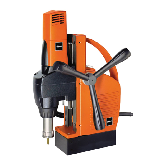
JCM125Q
7 270 35
®
Publicidad
Tabla de contenido

Manuales relacionados para Fein Slugger JCM125Q


Resumen de contenidos para Fein Slugger JCM125Q
- Página 1 3 41 01 165 21 0 - Umschlag.fm Seite 1 Mittwoch, 31. August 2011 2:58 14 ® ® JCM125Q 7 270 35 FEIN Service Headquarter C. & E. FEIN GmbH FEIN Power Tools Inc. Hans-Fein-Straße 81 1030 Alcon Street D-73529 Schwäbisch Gmünd-Bargau Pittsburgh, PA 15220 Telephone: (412) 922-8886 www.fein.com...
- Página 2 3 41 01 165 21 0.book Seite 2 Mittwoch, 7. September 2011 12:05 12 English _____________ Instruction manual___________________ Español _____________ Instrucciones de uso _________________...
- Página 3 3 41 01 165 21 0.book Seite 3 Mittwoch, 7. September 2011 12:05 12 For your safety. Read all safety warnings and 2) Electrical safety WARNING all instructions. Failure to fol- a) Power tool plugs must match the outlet. low the warnings and instructions may result Never modify the plug in any way.
- Página 4 3 41 01 165 21 0.book Seite 4 Mittwoch, 7. September 2011 12:05 12 c) Avoid accidental starting. Ensure the switch c) Disconnect the plug from the power source is in the off-position before plugging in. and/or the battery pack from the power tool Carrying power tools with your finger on before making any adjustments, changing the switch or plugging in power tools that...
- Página 5 3 41 01 165 21 0.book Seite 5 Mittwoch, 7. September 2011 12:05 12 Special safety instructions. Wear personal protective equipment. Depen- To prevent injuries, always keep your hands, ding on the application, use a face shield, clothing, etc. away from rotating swarf. The safety goggles or safety glasses.
- Página 6 3 41 01 165 21 0.book Seite 6 Mittwoch, 7. September 2011 12:05 12 Handling hazardous dusts When working with power To minimize the unwanted intake of these WARNING tools, such as when grinding, materials: sanding, polishing, sawing or for other work pro- –...
-
Página 7: Extension Cord
3 41 01 165 21 0.book Seite 7 Mittwoch, 7. September 2011 12:05 12 Emission values for sound (Two-figure – specifications as per ISO 4871) Sound emission A-weighted emission pressure power level measured at the workplace L (re 20 µPa), in decibels Measuring uncertainty K , in decibels Measured A-weighted sound power level L... - Página 8 3 41 01 165 21 0.book Seite 8 Mittwoch, 7. September 2011 12:05 12 Symbols. Symbol Explanation Action to be taken by the user This action is forbidden! Do not touch the rotating grinding wheels. Follow the instructions in the adjacent text or graphic! Be absolutely sure to read the enclosed documentation such as the Instruction Manual and the General Safety Instructions.
- Página 9 3 41 01 165 21 0.book Seite 9 Mittwoch, 7. September 2011 12:05 12 Character Unit of measure, national Explanation Revolution speed at no-load Electrical power Electric voltage Frequency Electric current intensity ° Angle width Mass ft, in Length, height, depth or diameter m, s, kg, A, mm, V, W, Basic and derived units of measure from the interna- Hz, N, °C, dB, min, m/s...
- Página 10 3 41 01 165 21 0.book Seite 10 Mittwoch, 7. September 2011 12:05 12 Technical description and specifications. Before mounting or replacing cutting tools or accessories, pull the power plug. WARNING This preventive safety measure rules out the danger of injuries through acci- dental starting of the power tool.
- Página 11 3 41 01 165 21 0.book Seite 11 Mittwoch, 7. September 2011 12:05 12 Type JCM125Q Reference number 7 270 35 Power input 700 W Output 450 W Power supply type No-load speed 550 rpm Speed, full load 440 rpm Weight according to EPTA-Procedure 01/2003 10.5 kg 23.1 lbs...
- Página 12 3 41 01 165 21 0.book Seite 12 Mittwoch, 7. September 2011 12:05 12 Assembly instructions. Before mounting or replacing cutting tools or accessories, pull the power plug. WARNING This preventive safety measure rules out the danger of injuries through acci- dental starting of the power tool.
- Página 13 3 41 01 165 21 0.book Seite 13 Mittwoch, 7. September 2011 12:05 12 Changing the tool. Secure the power tool with the safety strap supplied at all times, especially for WARNING work carried out at elevated heights, when drilling horizontally or above the head. If there is a power loss, or the power plug is pulled out, the magnetic holding power is not maintained.
- Página 14 3 41 01 165 21 0.book Seite 14 Mittwoch, 7. September 2011 12:05 12 Working instructions. Secure the power tool with the safety strap supplied at all times, especially for WARNING work carried out at elevated heights, when drilling horizontally or above the head. If there is a power loss, or the power plug is pulled out, the magnetic holding power is not maintained.
- Página 15 3 41 01 165 21 0.book Seite 15 Mittwoch, 7. September 2011 12:05 12 Starting and stopping the drill motor (Figure 8). Starting: Fig. 8 Switch the motor switch ON (I). Stopping: Switch the motor switch OFF (O). Shutting magnet OFF (O): Switch off the magnet with the magnet power switch.
- Página 16 3 41 01 165 21 0.book Seite 16 Mittwoch, 7. September 2011 12:05 12 Maintenance. Before mounting or replacing cutting tools or accessories, pull the power plug. WARNING This preventive safety measure rules out the danger of injuries through acci- dental starting of the power tool.
- Página 17 3 41 01 165 21 0.book Seite 17 Mittwoch, 7. September 2011 12:05 12 Provided Accessories. Fig. 10 Adapter (M 18x6/P 1,5) Pilot pin Key-type drill chuck ( in– with chuck key Safety strap Chip hook Cooling lubricant pump Chip guard Cooling lubricant hose Carrying case...
- Página 18 3 41 01 165 21 0.book Seite 18 Mittwoch, 7. September 2011 12:05 12 Para su seguridad. Lea íntegramente estas b) No utilice la herramienta eléctrica en un en- ADVERTENCIA advertencias de peligro e torno con peligro de explosión, en el que se instrucciones.
- Página 19 3 41 01 165 21 0.book Seite 19 Mittwoch, 7. September 2011 12:05 12 f) Si fuese imprescindible utilizar la herrami- g) Siempre que sea posible utilizar unos equi- enta eléctrica en un entorno húmedo, es ne- pos de aspiración o captación de polvo, cesario conectarla a través de un fusible di- asegúrese de que éstos estén apropiada- ferencial.
- Página 20 3 41 01 165 21 0.book Seite 20 Mittwoch, 7. September 2011 12:05 12 5) Servicio a) Únicamente haga reparar su herramienta eléctrica por un profesional, empleando ex- clusivamente piezas de repuesto originales. Solamente así se mantiene la seguridad de la herramienta eléctrica.
-
Página 21: Tratamiento De Materiales En Polvo Peligrosos
3 41 01 165 21 0.book Seite 21 Mittwoch, 7. September 2011 12:05 12 El motor con el útil montado no deberá deslizar Antes de la puesta en marcha inspeccione si hacia abajo por sí sólo. Si eso ocurre, reajuste están dañados el cable de red y el enchufe. -
Página 22: Cables De Prolongación
3 41 01 165 21 0.book Seite 22 Mittwoch, 7. September 2011 12:05 12 Emisión de ruidos (Indicación de dos cifras según ISO 4871) Emisión de ruido Nivel de presión de sonido L (re 20 µPa), medido con filtro A en el puesto de trabajo, en decibelios Inseguridad K , en decibelios... - Página 23 3 41 01 165 21 0.book Seite 23 Mittwoch, 7. September 2011 12:05 12 Simbolos. Simbolo Definición Acto realizado por el usuario ¡Esta acción está prohibida! No tocar las piezas en rotación de la herramienta eléctrica. ¡Seguir las instrucciones indicadas al margen! Imprescindible leer los documentos que se adjuntan, como las instrucci- ones de uso y las instrucciones generales de seguridad.
- Página 24 3 41 01 165 21 0.book Seite 24 Mittwoch, 7. September 2011 12:05 12 Símbolo Unidad nacional Definición Revoluciones en vacío Potencia Tensión eléctrica Frecuencia Intensidad ° Angulo Masa ft, in Longitud, ancho, altura, profundidad o diámetro m, s, kg, A, mm, V, W, Unidades básicas y unidades derivadas del sistema Hz, N, °C, dB, min, m/s internacional de unidades SI.
- Página 25 3 41 01 165 21 0.book Seite 25 Mittwoch, 7. September 2011 12:05 12 Descripción técnica y especificaciones. Saque la clavija del enchufe antes de montar o cambiar los útiles y accesorios. ADVERTENCIA Esta medida de seguridad preventiva evita los accidentes que pudieran pre- sentarse en caso de una puesta en marcha involuntaria.
- Página 26 3 41 01 165 21 0.book Seite 26 Mittwoch, 7. September 2011 12:05 12 Tipo JCM125Q Nº de referencia 7 270 35 Potencia absorbida 700 W Potencia útil 450 W Tensión de red R.p.m. en vacío 550 rpm Revoluciones bajo carga 440 rpm Peso según EPTA-Procedure 01/2003 10.5 kg...
- Página 27 3 41 01 165 21 0.book Seite 27 Mittwoch, 7. September 2011 12:05 12 Instrucciones de montaje. Saque la clavija del enchufe antes de montar o cambiar los útiles y accesorios. ADVERTENCIA Esta medida de seguridad preventiva evita los accidentes que pudieran pre- sentarse en caso de una puesta en marcha involuntaria.
- Página 28 3 41 01 165 21 0.book Seite 28 Mittwoch, 7. September 2011 12:05 12 Cambio de herramienta. Si en el trabajo a realizar existiese el peligro de que pueda caerse la herrami- ADVERTENCIA enta eléctrica, asegure ésta con la correa de seguridad suministrada, espe- cialmente al trabajar a una altura elevada, al taladrar horizontalmente, o al trabajar por encima de la cabeza.
- Página 29 3 41 01 165 21 0.book Seite 29 Mittwoch, 7. September 2011 12:05 12 Instrucciones para la operación. Si en el trabajo a realizar existiese el peligro de que pueda caerse la herrami- ADVERTENCIA enta eléctrica, asegure ésta con la correa de seguridad suministrada, especial- mente al trabajar a una altura elevada, al taladrar horizontalmente, o al trabajar por encima de la cabeza.
- Página 30 3 41 01 165 21 0.book Seite 30 Mittwoch, 7. September 2011 12:05 12 Encendido y apagado del motor de taladrar (Figura 8). Encendido: Fig. 8 Conecte el switch del motor (I). Apagado: Desconecte el switch del motor (O). Desactivación del imán (O): Desconecte el imán con el switch del Switch imán.
-
Página 31: Servicio Técnico
3 41 01 165 21 0.book Seite 31 Mittwoch, 7. September 2011 12:05 12 Mantenimiento. Saque la clavija del enchufe antes de montar o cambiar los útiles y accesorios. ADVERTENCIA Esta medida de seguridad preventiva evita los accidentes que pudieran pre- sentarse en caso de una puesta en marcha involuntaria. - Página 32 3 41 01 165 21 0.book Seite 32 Mittwoch, 7. September 2011 12:05 12 Accesorios que se adjuntan. Fig. 10 Adaptador (M 18x6/P 1,5) Broquero de Perno piloto corona dentada in– con llave Correa de seguridad Gancho para virutas Bomba de refrigeración Guarda contra virutas Manguera de...