Tabla de contenido
Publicidad
Idiomas disponibles
Idiomas disponibles
Enlaces rápidos
293 Wright Street • Delavan, WI 53115
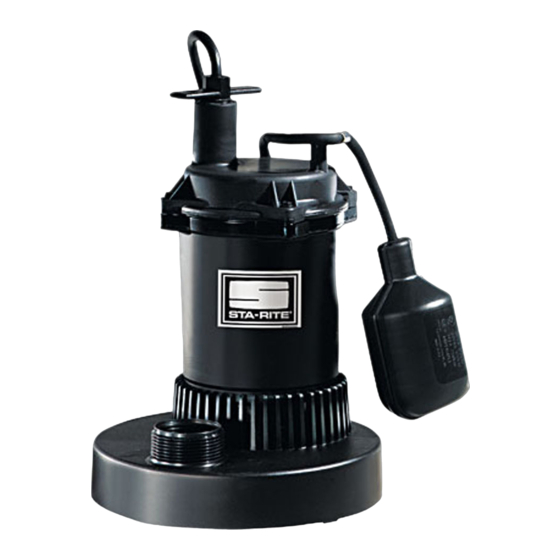
Submersible Sump Pumps
INSTALLATION, OPERATION, & PARTS MANUAL
SAFETY INFORMATION
Carefully read and follow all safety instructions in this
manual or on pump.
This is the safety alert symbol. When you see this
symbol on your pump or in this manual, look for one of the
following signal words and be alert to the potential for
personal injury!
warns about hazards that will cause serious
personal injury, death or major property damage if ignored.
warns about hazards that can cause serious
personal injury, death or major property damage if ignored.
warns about hazards that will or can cause
minor personal injury or property damage if ignored.
The word NOTICE indicates special instructions which are
important but not related to hazards.
Electrically powered sump pumps normally give many years
of trouble-free service when correctly installed, maintained,
and used. However, unusual circumstances (interruption of
power to the pump, dirt/debris in the sump, flooding that
exceeds the pump's capacity, electrical or mechanical failure
in the pump, etc.) may prevent your pump from functioning
normally. To prevent possible water damage due to flooding,
consult your dealer about installing a secondary sump
pump, a DC backup sump pump, and/or a high water alarm.
See the "Troubleshooting Chart" in this manual for informa-
tion about common sump pump problems and remedies. For
more information, see your dealer or call customer service
at 1-888-782-7483.
MOTOR, SWITCH, & CORD SPECIFICATIONS
Model
Motor
Number
HP
D12518T
1/4
D12518V
1/4
D125115T
1/4
D13318T
1/3
D13318V
1/3
D133115T
1/3
D15018T
1/2
D15018V
1/2
D150115T
1/2
D175110T
3/4
D175120T
3/4
D175120M
3/4
© 2006, Sta-Rite, Industries
1. Know the pump application, limitations, and potential
2. Disconnect power before servicing.
3. Release all pressure within system before servicing any
4. Drain all water from system before servicing.
5. Secure discharge line before starting pump. An unse-
6. Check hoses for weak or worn condition before each
7. Periodically inspect sump, pump and system compo-
8. Provide means of pressure relief for pumps whose dis-
9. Personal Safety:
10. When wiring an electrically driven pump, follow all elec-
11. This equipment is only for use on 115 volt and is
Individual
Max.
Branch Circuit
Load Amps
Required (Amps)
8.5
15
8.5
15
8.5
15
9.0
15
9.0
15
9.0
15
5.5
15
5.5
15
5.5
15
7.5
15
7.5
15
7.5
15
D125, D133, D150
and D175 Series
hazards.
component.
cured discharge line will whip, possibly causing personal
injury and/or property damage.
use, making certain that all connections are secure.
nents. Keep free of debris and foreign objects. Perform
routine maintenance as required.
charge line can be shut-off or obstructed.
a. Wear safety glasses at all times when working with
pumps.
b. Keep work area clean, uncluttered and properly light-
ed – replace all unused tools and equipment.
c. Keep visitors at a safe distance from work area.
d. Make workshop child-proof – with padlocks, master
switches, and by removing starter keys.
trical and safety codes that apply.
equipped with an approved 3-conductor cord and
3-prong, grounding-type plug.
Cord
Length
8'
13"(330)
8'
8-1/2"(216)
15'
13"(330)
8'
13"(330)
8'
8-1/2"(216)
15'
13"(330)
8'
13"(330)
8'
8-1/2"(216)
15'
13"(330)
10'
11"(279)
20'
11"(279)
20'
Switch Setting
in inches (mm)
On
Off
6"(152)
4"(102)
6"(152)
6"(152)
4"(102)
6"(152)
6"(152)
4"(102)
6"(152)
3-1/2"(89)
3-1/2"(89)
–
–
S502 (Rev. 1/4/07)
Publicidad
Tabla de contenido

Manuales relacionados para STA-RITE D125 Serie


Resumen de contenidos para STA-RITE D125 Serie
- Página 1 6"(152) D13318V 8’ 8-1/2"(216) 4"(102) D133115T 15’ 13"(330) 6"(152) D15018T 8’ 13"(330) 6"(152) D15018V 8’ 8-1/2"(216) 4"(102) D150115T 15’ 13"(330) 6"(152) D175110T 10’ 11"(279) 3-1/2"(89) D175120T 20’ 11"(279) 3-1/2"(89) D175120M 20’ – – © 2006, Sta-Rite, Industries S502 (Rev. 1/4/07)
- Página 2 INSTALLATION To reduce risk of electric shock, pull 1. Install pump in sump pit with minimum diameter of 10" plug before servicing. This pump has not been inves- (254mm) for models equipped with vertical switches tigated for use in swimming pool areas. Pump is sup- and 14"...
- Página 3 ELECTRICAL diameter and sump depth should be at least 14”. For best performance of pumps with vertical switches, sump diameter must be at least 10”. Hazardous Voltage. Can cause severe or 4. Plug piggyback switch cord into 115V AC outlet. Then, fatal electric shock.
-
Página 4: Replacement Parts List
MODELS D12518T, D12518V, D125115T D13318T, D13318V, D133115T D15018T, D15018V, D150115T REPLACEMENT PARTS LIST D125115T D12518T D12518V D133115T D13318T D13318V Description Qty. D150115T D15018T D15018V Power Cord Assembly See Chart, Below See Chart, Below See Chart, Below Cord Clamp Screw U30-955PS U30-955PS –... - Página 5 MODELS D175110T D175120T D175120M REPLACEMENT PARTS LIST Description Qty. D175110T D175120T D175120M Power Cord Assembly 1513001-TSU 1513002-TSU 1513002-TSU Hose and Clamp Assembly U74-68 U74-68 U74-68 Screw, Handle 14000 14000 14000 Float Bracket/Handle PS54-14SS PS54-14SS – Switch Cord Clamp CC0030-13 CC0030-13 –...
-
Página 6: Troubleshooting Chart
LIMITED WARRANTY Sta-Rite Industries warrants to the original consumer of the products listed below, that they will be free from defects in material and work- manship for the Warranty Period from the date of original installation or manufacture as noted. -
Página 7: Bombas Sumergibles De Sumidero
6"(152) D13318V 8’ 8-1/2"(216) 4"(102) D133115T 15’ 13"(330) 6"(152) D15018T 8’ 13"(330) 6"(152) D15018V 8’ 8-1/2"(216) 4"(102) D150115T 15’ 13"(330) 6"(152) D175110T 10’ 11"(279) 3-1/2"(89) D175120T 20’ 11"(279) 3-1/2"(89) D175120M 20’ – – © 2006, Sta-Rite, Industries S502 (Rev. 1/4/07) -
Página 8: Descripción
flotación. La profundidad del sumidero debe ser de 14" (356 mm). ADVERTENCIA Para reducir el riesgo de choque eléc- Construya el foso del sumidero de baldosa, hormigón, acero o trico, desenchufe antes de realizar trabajos de reparación o plástico. Consulte todos los códigos locales con respecto a los mantenimiento. -
Página 9: Información Eléctrica
INFORMACIÓN ELÉCTRICA con conmutadores anclados (de traba), el diámetro y la profun- didad del sumidero deben ser por lo menos de 14". Para obten- ADVERTENCIA er el mejor rendimiento con bombas de conmutadores verti- Tensión peligrosa. Existe el riesgo de cales, el diámetro del sumidero debe ser por lo menos de 10". -
Página 10: Lista De Repuestos
MODELOS D12518T, D12518V, D125115T D13318T, D13318V, D133155T D15018T, D15018V, D150150T LISTA DE REPUESTOS D125115T D12518T D12518V D133115T D13318T D13318V Clave Descripción Cant. D150115T D15018T D15018V Ensamblaje de cordón de corriente Ver tabla a continuación Ver tabla a continuación Ver tabla a continuación Tornillo de abrazadera de cordon U30-955PS U30-955PS... - Página 11 MODELOS D175110T D175120T D175120M LISTA DE REPUESTOS Clave Descripción Cant. D175110T D175120T D175120M Ensamblaje de cordón de corriente 1513001-TSU 1513002-TSU 1513002-TSU Unidad de manguera y abrazadera U74-68 U74-68 U74-68 Soporte/Tornillo 14000 14000 14000 Soporte/Mango del flotador PS54-14SS PS54-14SS – Abrazadera de cordón del conmutador CC0030-13 CC0030-13 –...
-
Página 12: Tabla De Localización De Fallas
El único recurso del comprador, y la única obligación de Sta-Rite Industries serán el de reparar o reemplazar los productos defectuosos (a opción de Sta-Rite Industries). El comprador acuerda pagar por toda la mano de obra y los cargos de envío asociados con esta garantía y solicitar un servicio de garantía a través del representante que haya realizado la instalación, tan pronto como se descubra el problema.