Tabla de contenido
Publicidad
Idiomas disponibles
Idiomas disponibles
Enlaces rápidos
Publicidad
Tabla de contenido

Manuales relacionados para Festo HMPL-M Serie


Resumen de contenidos para Festo HMPL-M Serie
- Página 1 Zwischenstellungsmodul Intermediate position module HMPL-...-M..-... (de) Bedienungs- anleitung (en) Operating instructions (es) Instrucciones de utilización (fr) Notice d’utilisation (it) Istruzioni d’uso (sv) Bruksanvisning 396 660 0009NH...
- Página 2 ..............Festo HMPL-...-M..-... 0009NH...
-
Página 3: Bedienteile Und Anschlüsse
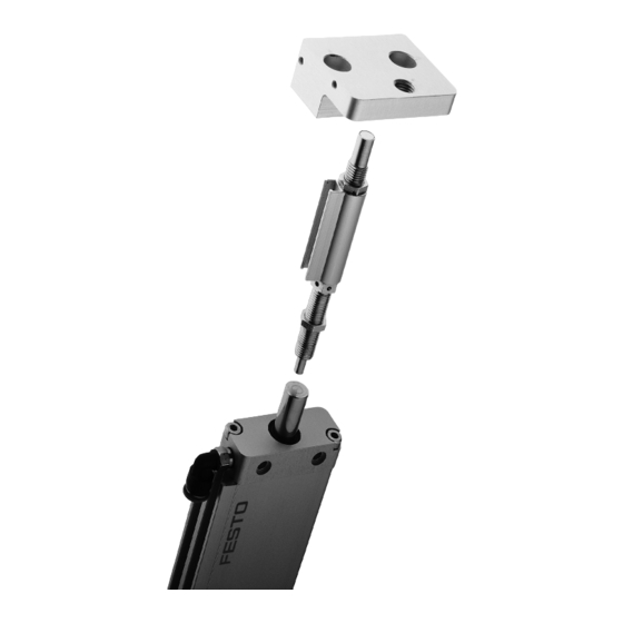
Druckluftanschluss für ausgefahrene Kol- Gewindebohrung für Anschlagelement benstange Befestigungsflansch mit Durchgangsboh- Durchgangsbohrungen zur Befestigung rungen zur Befestigung am Linearmodul des Zwischenstellungszylinders am Linear- HMPL-... modul HMPL-... Kolbenstange (Anschlagbolzen) Steckverschraubung nicht im Lieferumfang enthalten Bild 1 Festo HMPL-...-M..-... 0009NH Deutsch... - Página 4 Das Konstruktionsprinzip ermöglicht sowohl das Anfahren, als auch das Durchfah- ren der Zwischenposition aus beiden Endlagen. Das Zwischenstellungsmodul HMPL-...-M..-... wird bestimmungsgemäß verwendet zur Positionierung der Kolbenstange von Festo Linearmodulen des Typs HMPL-... in einer Stellung zwischen den Endlagen. Festo HMPL-...-M..-... 0009NH Deutsch...
-
Página 5: Voraussetzungen Für Den Produkteinsatz
HMPL-... befestigen. Bild 4 Das Anziehdrehmoment beträgt 3 Nm. 2. Anschlagelement bis zur gewünschten Zwischenposition (Grobeinstellung) in den Befestigungsflansch eindrehen und mit Kontermutter sichern. Die Anziehdrehmomente der Kontermutter sind in nachfolgender Tabelle zusammen- gefasst: Bild 5 Festo HMPL-...-M..-... 0009NH Deutsch... - Página 6 3. Zwischenstellungszylinder mit den beilie- genden Zentrierringen (Z) und Schrauben am Grundprofil des HMPL-... (siehe Bild 8) befestigen. Das Anziehdrehmoment be- trägt: HMPL-12- HMPL-16(20)- ...-M..-M... Anziehdreh- 3 Nm 5 Nm moment Schrauben- größe Bild 8 Bild 9 Festo HMPL-...-M..-... 0009NH Deutsch...
- Página 7 Ventilinsel Typ CPV..-... nach Bild 10). Bild 10 Einbau elektrisch Zur Positionsabfrage der Zwischenposition Verwenden Sie Näherungsschalter vom Typ SME-8-.../SMT-8-...-B. Diese können in folgender Nut platziert werden: – Nut des Zwischenstellungszylinders Bild 11 – Nut des Anschlagelements. Festo HMPL-...-M..-... 0009NH Deutsch...
- Página 8 S Stellen Sie sicher, dass das Linearmodul nicht gegen eine unbelüftete Kam- mer fährt (dies ist dann der Fall, wenn der Zwischenstellungszylinder sehr schnell entlüftet wird). Andernfalls überschreitet das Linearmodul innerhalb kürzester Zeit die Maxi- malgeschwindigkeit. Festo HMPL-...-M..-... 0009NH Deutsch...
- Página 9 Betriebsdruck des HMPL-... ist. Andernfalls ist die Kraft des Linearmoduls während der Dämpfung größer und bewirkt kurzfristig ein Überfahren der Zwischenposition. Zur Einstellung einer Zwischenposition: Justieren Sie das Anschlagelement mit Hilfe der beigefügten Bedienungsanlei- tung des Anschlagelements YSRWJ-..Festo HMPL-...-M..-... 0009NH Deutsch...
- Página 10 Linearmoduls unter Berücksichtigung des oben genannten Bewe- gungsablaufs. Prüfen Sie anhand der Schaubilder im Kapitel Kennlinien, ob die zulässige Aus- fahrgeschwindigkeit des Zwischenstellungszylinder eingehalten wird. Der Zwi- schenstellungszylinder ist gegebenenfalls zu drosseln (Abluftdrosselung). Beenden Sie den Probelauf. Festo HMPL-...-M..-... 0009NH Deutsch...
-
Página 11: Bedienung Und Betrieb
Plötzliches Freisetzen von anstehenden Drücken führt zu unerwartet hohen Rückstoßkräften. S Stellen Sie sicher, dass Linearmodul und Zwischenstellungsmodul entlüftet sind. Nutzen Sie die Möglichkeit einer Überholung Ihrer HMPL-...-M..-... durch unse- ren Reparaturservice. Ansonsten ist das Zwischenstellungsmodul wartungsfrei. Festo HMPL-...-M..-... 0009NH Deutsch... - Página 12 Masse in der Masse zu groß Masse reduzieren E dl g /Z i h Endlage/Zwischenposition Stoßdämpfer defekt Stoßdämpfer anhand Be- dienungsanleitung des An- schlagelements austau- schen Linearmodul fährt gegen Hubseitige Zylinderkammer unbelüftete Kammer am Linearmodul belüften Bild 17 Festo HMPL-...-M..-... 0009NH Deutsch...
-
Página 13: Technische Daten
St (gehärtet) Anschlagelement: (siehe dessen Bedienungsanleitung) Dichtungen: Ca. Gewicht des Zwischen- positionsmoduls 0-Hub 0,31 kg 0,51 kg 0,58 kg Pro 10 mm Hub 0,018 kg 0,024 kg 0,024 kg am Zwischenstellungszylinder (bei 6 bar) Bild 18 Festo HMPL-...-M..-... 0009NH Deutsch... - Página 14 HMPL-...-M..-... Kennlinien Maximale Ausfahrgeschwindigkeit v [m/s] des Zwischenstellungszylinder (HMDZF-...) in Abhängigkeit der Nutzlastmasse des Linearmoduls HMPL-... m [kg]. v [m/s] Bild 19 Festo HMPL-...-M..-... 0009NH Deutsch...
-
Página 15: Operating Parts And Connections
HMPL-..Through holes for fastening the intermedi- ate position cylinder to the linear module Piston rod (stop bolt) type HMPL-..Screw connector not included in delivery Fig. 1 Festo HMPL-...-M..-... 0009NH English... - Página 16 The construction design enables the intermediate position to be reached and passed from both end positions. The intermediate position module type HMPL-...-M..-... is designed for positioning the piston rod of Festo linear modules of type HMPL-... at a point between the end positions. Festo HMPL-...-M..-... 0009NH English...
- Página 17 2. Screw in the positioning element up to the desired intermediate position (rough set- ting) in the fastening flange and secure with lock nut. The tightening torques of the lock nuts are shown in the table below. Fig. 5 Festo HMPL-...-M..-... 0009NH English...
- Página 18 (Z) and screws provided to the basic profile of the HMPL-... (see Fig. 8). The tightening torque is: HMPL-12- HMPL-16(20)- Type ...-M..-M... Tightening 3 Nm 5 Nm torque Screw size Fig. 9 Fig. 8 Festo HMPL-...-M..-... 0009NH English...
- Página 19 Fitting electric components Interrogating the intermediate position Use proximity switches of type SME-8-.../SMT-8-...-B. These can be placed as follows: – in the groove of the intermediate position cylinder Fig. 11 – in the groove of the positioning element. Festo HMPL-...-M..-... 0009NH English...
- Página 20 S Make sure that the linear module does not move against a non-pressurized chamber (this is the case when the intermediate position cylinder is ex- hausted very quickly). Otherwise, the linear module will very soon exceed the maximum speed. Festo HMPL-...-M..-... 0009NH English...
- Página 21 Otherwise, the force of the linear module is greater during cushioning and will result briefly in the intermediate position being passed. Setting an intermediate position Adjust the positioning element with the aid of the operating instructions sup- plied with the positioning element type YSRWJ-..Festo HMPL-...-M..-... 0009NH English...
- Página 22 With the aid of the diagrams in the chapter “Characteristic curves”, check to see whether the permitted extending speed of the intermediate position cylin- der is observed. If necessary, the intermediate position cylinder must also be restricted (exhaust restriction). Conclude the test run. Festo HMPL-...-M..-... 0009NH English...
-
Página 23: Dismantling And Repairs
S Make sure that both the linear module and the intermediate position module are exhausted. Make use of the opportunity to have your HMPL-...-M..-... overhauled by our repair service. Otherwise the intermediate position module does not require any mainten- ance. Festo HMPL-...-M..-... 0009NH English... -
Página 24: Eliminating Faults
Replace the shock ab- sorber in accordance with the operating instructions for the positioning element Linear module strikes Pressurize the cylinder against a non-pressurized chamber on the stroke side chamber of the linear module Fig. 17 Festo HMPL-...-M..-... 0009NH English... -
Página 25: Technical Specifications
Seals: Approximate weight of the intermediate position module 0-stroke 0.31 kg 0.51 kg 0.58 kg per 10 mm stroke 0.018 kg 0.024 kg 0.024 kg On the intermediate position cylinder (at 6 bar) Fig. 18 Festo HMPL-...-M..-... 0009NH English... -
Página 26: Characteristic Curves
HMPL-...-M..-... Characteristic curves Maximum extending speed v [m/s] of the intermediate position cylinder (HMDZF-...) as a factor of the work load mass of the linear module type HMPL-... m [kg]. v [m/s] Fig. 19 Festo HMPL-...-M..-... 0009NH English... - Página 27 Brida de fijación con agujeros pasantes para fijación en el módulo lineal tipo Agujeros pasantes para fijar el cilindro de HMPL-... posición intermedia al módulo lineal tipo HMPL-... Vástago (bulón de tope) Racores no incluidos en el suministro Fig. 1 Festo HMPL-...-M..-... 0009NH Español...
-
Página 28: Método De Funcionamiento Y Utilización
El módulo de posición intermedia tipo HMPL-...-M..-... está diseñado para el posicio- nado del vástago de los módulos lineales Festo del tipo HMPL-... en un punto entre las posiciones finales. Festo HMPL-...-M..-... 0009NH Español... -
Página 29: Condiciones De Utilización
2. Atornillar el elemento de posicionado hasta la posición intermedia deseada (ajuste aproximado) en la brida de fijación y asegurarlo con una tuerca: Los pares de apriete de las tuercas se indican en la tabla inferior. Fig. 5 Festo HMPL-...-M..-... 0009NH Español... - Página 30 (Z) y tornillos suministrados al perfil básico del HMPL-... (véase Fig. 8) El par de apriete es: HMPL-12- HMPL-16(20)- Tipo ...-M..-M... Par de 3 Nm 5 Nm apriete Tamaño del tornillo Fig. 9 Fig. 8 Festo HMPL-...-M..-... 0009NH Español...
- Página 31 Interrogación de la posición intermedia Usar detectores de proximidad del tipo SME-8-.../SMT-8-...-B. Estos pueden colocarse como sigue: – en la ranura del cilindro de posición intermedia Fig. 11 – en la ranura del elemento de posicio- nado. Festo HMPL-...-M..-... 0009NH Español...
- Página 32 S Asegurarse de que los módulos lineales no se desplazan contra cámaras sin presión (esto se produce si en la posición intermedia del cilindro se descarga el aire del lado contrario al movimiento). De lo contrario, el módulo lineal sobrepasará la velocidad máxima. Festo HMPL-...-M..-... 0009NH Español...
- Página 33 Ajuste de una posición intermedia Ajustar el elemento de posicionado con ayuda de las instrucciones de funcio- namiento suministradas con el elemento de posicionado tipo YSRWJ-... Festo HMPL-...-M..-... 0009NH Español...
- Página 34 Con la ayuda de los diagramas del capítulo “Curvas características”, compro- bar si se observa la velocidad de avance permitida del cilindro de posición intermedia. Si es necesario, el aire (de escape) del cilindro de posición inter- media también debe estrangularse. Finalizar el funcionamiento de prueba. Festo HMPL-...-M..-... 0009NH Español...
-
Página 35: Funcionamiento
S Asegurarse de que tanto el módulo lineal como el de posición intermedia están descargados. Aproveche la oportunidad para hacer revisar el HMPL-... por nuestro servicio de asistencia técnica. El módulo de posición intermedia no requiere ningún mantenimiento. Festo HMPL-...-M..-... 0009NH Español... -
Página 36: Accesorios
El módulo lineal golpea Presurizar la cámara del contra una cámara sin cilindro en el lado de la presurizar carrera del módulo lineal Fig. 17 Festo HMPL-...-M..-... 0009NH Español... -
Página 37: Especificaciones Técnicas
Peso aproximado del módulo de posición intermedia carrera 0 0,31 kg 0,51 kg 0,58 kg por cada 10 mm de carrera 0,018 kg 0,024 kg 0,024 kg En el cilindro de posición intermedia (a 6 bar) Fig. 18 Festo HMPL-...-M..-... 0009NH Español... -
Página 38: Curvas Características
HMPL-...-M..-... Curvas características Velocidad de avance máxima v [m/s] del cilindro de posición intermedia (HMDZF-...) en función de la masa de la carga del módulo lineal tipo HMPL-... m [kg]. v [m/s] Fig. 19 Festo HMPL-...-M..-... 0009NH Español... - Página 39 HMPL-... Trous de passage pour la fixation du vérin de position intermédiaire sur le module Tige de piston (butée) linéaire HMPL-... Raccord d’enfichage non compris dans la fourniture Fig. 1 Festo HMPL-...-M..-... 0009NH Français...
-
Página 40: Fonctionnement Et Utilisation
Le module de position intermédiaire HMPL-...-M..-... est prévu pour le positionne- ment de la tige de piston des modules linéaires Festo de type HMPL-... à un empla- cement situé entre les fins de course. -
Página 41: Conditions Préalables À L'utilisation Du Produit
2. Visser l’élément de butée jusqu’à la posi- tion intermédiaire souhaitée (réglage approximatif ) dans la bride de fixation et le bloquer à l’aide du contre-écrou. Les couples de serrage du contre-écrou sont répertoriés dans le tableau suivant : Fig. 5 Festo HMPL-...-M..-... 0009NH Français... - Página 42 HMPL-... (voir Fig. 8). Le couple de serrage est de : HMPL-12- HMPL-16(20)- Type ...-M..-M... Couple de 3 Nm 5 Nm serrage Surplat Fig. 9 Fig. 8 Festo HMPL-...-M..-... 0009NH Français...
- Página 43 Pour la détection de la position intermédiaire Utiliser des capteurs de proximité de type SME-8-.../SMT-8-...-B. Ceux-ci peuvent être placés dans la rainure suivante : – Rainure du vérin de position intermé- Fig. 11 diaire – Rainure de l’élément de butée. Festo HMPL-...-M..-... 0009NH Français...
- Página 44 S S’assurer que le module linéaire ne se dirige pas vers une chambre non ali- mentée (c’est le cas notamment lorsque le vérin de position intermédiaire est mis à l’échappement très rapidement). Sinon, le module linéaire dépasse en très peu de temps la vitesse maximale. Festo HMPL-...-M..-... 0009NH Français...
- Página 45 Pour le réglage d’une position intermédiaire : Ajuster l’élément de butée en suivant les instructions de la notice d’utilisation de l’élément de butée YSRWJ-..Festo HMPL-...-M..-... 0009NH Français...
- Página 46 Vérifier, à l’aide des schémas du chapitre Courbes caractéristiques, que la vitesse de sortie admissible du vérin de position intermédiaire est respectée. Il peut s’avérer nécessaire dans certains cas de limiter le débit du vérin de posi- tion intermédiaire (à l’échappement). Terminer la passe d’essai. Festo HMPL-...-M..-... 0009NH Français...
-
Página 47: Utilisation Et Fonctionnement
S S’assurer que le module linéaire et le module de position intermédiaire sont mis à l’échappement. Ne pas hésiter à faire appel au service après-vente Festo pour la réparation du module HMPL-...-M..-... Sinon, le module de position intermédiaire est exempt de maintenance. - Página 48 – avec une pression supé- rieure au HMPL-... Commande incorrecte Vérifier le schéma pneuma- tique Module de position inter- Le retourner à Festo médiaire défectueux Impact brutal de la masse Vitesse de déplacement/ Réduire la vitesse de en mouvement en fin de masse excessive déplacement/masse...
-
Página 49: Caractéristiques Techniques
Poids approximatif du module de position intermédiaire Course 0 0,31 kg 0,51 kg 0,58 kg Pour 10 mm de course 0,018 kg 0,024 kg 0,024 kg Sur le vérin de position intermédiaire (pour 6 bar) Fig. 18 Festo HMPL-...-M..-... 0009NH Français... -
Página 50: Courbes Caractéristiques
HMPL-...-M..-... Courbes caractéristiques Vitesse de sortie maximale v [m/s] du vérin de position intermédiaire (HMDZF-...) en fonction de la masse de la charge utile du module linéaire HMPL-... m [kg]. v [m/s] Fig. 19 Festo HMPL-...-M..-... 0009NH Français... -
Página 51: Elementi Operativi E Attacchi
Fori passanti per il fissaggio del cilindro intermedio al modulo lineare HMPL-... Flangia di fissaggio con fori passanti per il fissaggio del modulo lineare HMPL-..Raccordo a innesto non compreso nella dotazione Stelo (perno di arresto) Fig. 1 Festo HMPL-...-M..-... 0009NH Italiano... -
Página 52: Funzionamento E Utilizzo
Il modulo intermedio HMPL-...-M..-... viene impiegato per gli usi consentiti per il posizionamento dello stelo dei moduli lineari Festo HMPL-... in una posizione com- presa tra i fine corsa. Festo HMPL-...-M..-... 0009NH Italiano... -
Página 53: Condizioni Di Utilizzo
2. Avvitare l’elemento d’arresto fino alla posizione intermedia desiderata (regola- zione di massima) nella flangia di fissag- gio e fissarlo con il controdado. Le coppie di serraggio del controdado sono riportate nella seguente tabella. Fig. 5 Festo HMPL-...-M..-... 0009NH Italiano... - Página 54 (Z) allegati e le viti al profi- lato di base dell’HMPL-... (vedi Fig. 8). La coppia di serraggio corrisponde a: HMPL-12- HMPL-16(20)- Tipo ...-M..-M... Coppia di 3 Nm 5 Nm serraggio Dimensione viti Fig. 9 Fig. 8 Festo HMPL-...-M..-... 0009NH Italiano...
- Página 55 Montaggio delle parti elettriche Per il rilevamento della posizione intermedia Impiegare esclusivamente finecorsa ma- gnetici di tipo SME-8-.../SMT-8-...-B Essi possono essere sistemanti nella se- guente scanalatura: – scanalatura del cilindro intermedio Fig. 11 – scanalatura dell’elemento d’arresto. Festo HMPL-...-M..-... 0009NH Italiano...
-
Página 56: Messa In Servizio
S Accertarsi che il modulo lineare non si sposti verso una camera non alimen- tata (ciò avviene quando il cilindro intermedio viene scaricato molto veloce- mente). Il modulo lineare supera altrimenti in breve tempo la velocità massima. Festo HMPL-...-M..-... 0009NH Italiano... - Página 57 In caso contrario, la forza del modulo lineare durante l’ammortizzazione è maggiore, conducendo a un superamento immediato della posizione inter- media. Regolazione della posizione intermedia: Regolare l’elemento d’arresto riferendosi alle istruzioni d’uso allegate dell’ele- mento d’arresto YSRWJ-..Festo HMPL-...-M..-... 0009NH Italiano...
- Página 58 Riferendosi ai grafici riportati nel capitolo Curve caratteristiche, accertarsi che venga rispettata la velocità di avanzamento ammessa del cilindro intermedio. Strozzare eventualmente il cilindro intermedio (regolatore di portata di sca- rico). Terminare la prova di funzionamento. Festo HMPL-...-M..-... 0009NH Italiano...
-
Página 59: Smontaggio E Riparazione
S Verificare che il modulo lineare e il modulo intermedio non siano sotto pressione. Si consiglia di utilizzare la possibilità di far revisionare l’HMPL-... –M...-... dal nostro servizio riparazioni. Il modulo intermedio non necessita altrimenti di manutenzione. Festo HMPL-...-M..-... 0009NH Italiano... -
Página 60: Eliminazione Dei Guasti
– con una pressione mag- giore di HMPL-... Azionamento errato Verificare lo schema pneu- matico Modulo intermedio guasto Spedire il modulo a Festo Urto violento della massa Velocità di spostamento/ Ridurre la velocità di spo- in movimento al fine corsa/ massa eccessiva... -
Página 61: Dati Tecnici
(vedi relative Istruzioni d’uso) Guarnizioni: Peso appr. del modulo intermedio corsa 0 0,31 kg 0,51 kg 0,58 kg per ogni 10 mm di corsa 0,018 kg 0,024 kg 0,024 kg Sul cilindro intermedio (a 6 bar) Fig. 18 Festo HMPL-...-M..-... 0009NH Italiano... -
Página 62: Curve Caratteristiche
HMPL-...-M..-... Curve caratteristiche Velocità di avanzamento massima v [m/s] del cilindro intermedio (HMDZF-...) in funzione della massa del carico utile del modulo lineare HMPL-... m [kg]. v [m/s] Fig. 19 Festo HMPL-...-M..-... 0009NH Italiano... -
Página 63: Komponenter Och Anslutningar
Tryckluftsanslutning för utkörd kolvstång Gängade hål för dämpningselement Genomgående hål för montering av mellan- lägescylindern på den linjärmodul HMPL-... Monteringsfläns med genomgående hål för montering på linjärmodul HMPL-... Instickskopplingar ingår inte i leveransen Kolvstång (anslagsbult) Bild 1 Festo HMPL-...-M..-... 0009NH Svenska... - Página 64 Konstruktionsprincipen gör det möjligt både att köra mot och köra förbi mellanlä- get från båda ändlägen. Mellanlägesmodulen HMPL-...-M..-... är avsedd för att användas för positionering av kolvstången i Festo linjärmoduler typ HMPL-... i ett läge mellan ändlägena. Festo HMPL-...-M..-... 0009NH Svenska...
- Página 65 (A) på linjärmodulen HMPL-... Åtdragningsmomentet är 3 Nm. Bild 4 2. Skruva i dämpningselementet till önskat mellanläge (grovinställning) i monterings- flänsen och säkra med låsmuttern. Låsmuttrarnas åtdragningsmoment fram- går av efterföljande tabell: Bild 5 Festo HMPL-...-M..-... 0009NH Svenska...
- Página 66 3. Fäst mellanlägescylindern på basprofilen på HMPL-... med medföljande centrer- ringar (Z) och skruvar (se Bild 8). Åtdrag- ningsmomentet är: HMPL-12- HMPL-16(20)- ...-M..-M... Åtdrag- 3 Nm 5 Nm ningsmo- ment Skruvdi- mension Bild 8 Bild 9 Festo HMPL-...-M..-... 0009NH Svenska...
- Página 67 – Linjärmodul (t.ex. styrning med Com- pact-Performance ventilterminal CPV..-... enligt bild 10). Bild 10 Elektrisk montering För positionsavläsning av mellanläget Använd endast induktiv givare av typen SME-8-.../SMT-8-...-B. Dessa kan placeras i följande spår: – Mellanlägescylinderns spår – Dämpningselementets spår. Bild 11 Festo HMPL-...-M..-... 0009NH Svenska...
- Página 68 Den linjärmodulen förstörs om den tillåtna in-/utkörningstiden underskrids. S Säkerställ att den linjärmodulen inte går mot en ej påluftad kammare (detta blir fallet, om mellanlägescylindern avluftas mycket snabbt). I annat fall överskrider den linjärmodulen den maximala hastigheten på myk- ket kort tid. Festo HMPL-...-M..-... 0009NH Svenska...
- Página 69 I annat fall är den linjärmodul kraft under dämpningen större, och detta har som följd att mellanläget påkort tid blir förbikört. Inställning av ett mellanläge: Justera dämpningselementet med hjälp av bifogad bruksanvisning till dämp- ningselement YSRWJ-..Festo HMPL-...-M..-... 0009NH Svenska...
- Página 70 Starta en provkörning med låg frekvens med hjälp av bruksanvisningen till linjärmodulen i betraktande av den ovannämnda rörelsen. Kontrollera med hjälp av diagrammen i kapitlet “Kurvor”, om mellanlägescylin- derns tillåtna utkörningshastighet innehålls. Om nödvändigt skall mellanläges- cylindern strypas (strypning av avluften). Avsluta provkörningen. Festo HMPL-...-M..-... 0009NH Svenska...
-
Página 71: Demontering Och Reparation
Demontering och reparation Demontering: Notera Plötslig tryckavlastning leder till oväntat höga returstötkrafter. S Kontrollera att den linjärmodulen och mellanlägesmodulen är avluftade. Utnyttja möjligheten att låta vår reparationsservice se över din HMPL-...-M-..-... I övrigt är mellanlägesmodulen underhållsfri. Festo HMPL-...-M..-... 0009NH Svenska... - Página 72 Reducera förflyttningshas- hårt i ändläget/mellanläget het / för stor massa tigheten / massan Defekt stötdämpare Byt ut stötdämparen med hjälp av bruksanvisningen till dämpningselementet Linjärmodulen går mot en Pålufta cylinderkammaren ej påluftad kammare på Linjäramodulen Bild 17 Festo HMPL-...-M..-... 0009NH Svenska...
-
Página 73: Tekniska Data
Stål Anslagsbultar: Stål (härdat) Dämpningselement: (se dess bruksanvisning) Packningar Mellanlägesmodulens ca vikt 0-slag 0,31 kg 0,51 kg 0,58 kg per 10 mm slag 0,018 kg 0,024 kg 0,024 kg Vid mellanlägescylindern (vid 6 bar) Bild 18 Festo HMPL-...-M..-... 0009NH Svenska... - Página 74 HMPL-...-M..-... Kurvor Mellanlägescylinderns (HMDZF-...) maximala utkörningshastighet v [m/s] i relation till lasten på linjärmodulen HMPL-... m [kg]. v [m/s] Bild 19 Festo HMPL-...-M..-... 0009NH Svenska...
- Página 75 HMPL-...-M..-... Festo HMPL-...-M..-... 0009NH...
- Página 76 Copyright: cation de son contenu sont interdites, sauf autorisation Festo AG & Co., écrite expresse. Tout manquement à cet règle est illicite et Postfach 6040 expose son auteur au versement de dommages et intérêts.