Tabla de contenido
Publicidad
Idiomas disponibles
Idiomas disponibles
Enlaces rápidos
Publicidad
Capítulos
Tabla de contenido

Resumen de contenidos para Riello GS5
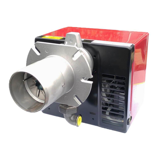
- Página 1 Installation, use and maintenance instructions Instrucciones para la instalación, uso y mantenimiento Forced draught gas burner Quemador de gas de aire soplado One stage operation Funcionamiento de una llama CODE - CÓDIGO MODEL - MODELO TYPE - TIPO 3755281 552 T80 2902773 (2) - 09/2014...
-
Página 3: Tabla De Contenido
INDEX BURNER DESCRIPTION ... Electrical wiring ....Burner equipment ....Fixing of the electrical wiring . -
Página 4: Technical Data
TECHNICAL DATA 2.1 TECHNICAL DATA Thermal power 23 – 65 kW – 20,000 – 56,000 kcal/h Net heat value: 8 – 12 kWh/Nm 7,000 – 10,340 kcal/Nm Natural gas (Family 2) Pressure: min. 15 mbar max. 100 mbar ± Electrical supply Single phase, 220 V 60Hz Motor... -
Página 5: Correlation Between Gas Pressure And Burner Output
2.4 CORRELATION BETWEEN GAS PRESSURE AND BURNER OUTPUT To obtain the maximum output, a gas head pressure of 5.2 mbar is measured with the combustion chamber at 0 mbar using gas G20 with a net heat value of 10 kWh/Nm (8,570 kcal/Nm D4292 20.000... -
Página 6: Probe-Electrode Positioning
3.2 PROBE - ELECTRODE POSITIONING IMPORTANT Do not turn the starting electrode but leave it as shown in the drawing; if the starting electrode is put near the ionization probe, the amplifier of the control box might be damaged. Put the ceramic Ionization near the diffuser disc probe... -
Página 7: Electrical Wiring
ELECTRICAL WIRING LEGEND BO - Ionization probe - Capacitor - Elecrode - Fuse T6A - Remote lock-out signal (220V - 0.5 A max.) MV - Motor SG - Gas pressure switch - Limit thermostat SPA - Air pressure switch - Safety thermostat XB - Burner terminal board - Burner earth CONTROL BOX... -
Página 8: Fixing Of The Electrical Wiring
3.5 FIXING OF THE ELECTRICAL WIRING All the electrical wires, which are to be connected into the terminal board (6, fig. 1, page 1) should pass through the cable grommet (5, fig. 1). All the electrical wires, which are to be connected into the terminal board must be gripped in the cable clamps (7, fig. -
Página 9: Combustion Check
4.3 COMBUSTION CHECK CO 2 It is advisable to not exceed 10% of CO 2 (natural gas) , in order to avoid the risk that small changes of the adjustments due, for instance, at draught variation, may cause combustion with insufficient air and conse- quently formation of CO. - Página 10 BURNER STARTING DIFFICULTIES DIFFICULTIES CAUSES The ionization probe is earthed or not in contact with the flame, or its wiring to the control box is broken, or there is a fault on its insulation to The burner goes through the earth.
-
Página 11: Descripción Del Quemador
INDICE DESCRIPCIÓN DEL QUEMADOR ..1 3.4 Instalación eléctrica..... . 5 1.1 Material suministrado ....1 3.5 Fijación de los cables eléctricos. -
Página 12: Datos Técnicos
DATOS TÉCNICOS 2.1 DATOS TÉCNICOS Potencia térmica 23 ÷ 65 kW 20.000 ÷ 56.000 kcal/h Pci: 8 12 kWh/Nm 7.000 ÷ 10.340 kcal/Nm Gas natural (Familia 2) Presión: mín. 15 mbar – máx. 100 mbar ± Alimentación eléctrica Monofasica, 220 V 60Hz Motor 220V / 1 A... -
Página 13: Correlación Entre Presión Del Gas Y Potencia
2.4 CORRELACIÓN ENTRE PRESIÓN DEL GAS Y POTENCIA Para obtener la potencia máxima se requieren 5.2 mbar medidos en el manguito con cámara de combus- tión a 0 mbar y gas G20 - Pci = 10 kWh/Nm (8.570 kcal/Nm D4292 20.000 30.000 40.000... -
Página 14: Posicionamiento Sonda Electrodo
3.2 POSICIONAMIENTO SONDA - ELECTRODO IMPORTANTE No gire el electrodo de encendido sino que déjelo colocado como muestra la figura; si se lo acercase a la sonda de ionización, podría averiar el amplificador del caja de control. Apoye la cerámica a la hélice Sonda Difusor... -
Página 15: Instalación Eléctrica
INSTALACIÓN ELÉCTRICA LEGEND BO - Sonda Condensador Electrodo - Fusible T6A - Señalización de bloqueo a distancia (220V - 0,5A max.) MV - Motor SG - Presóstato aire - Termostato de regulación SPA - Presóstato aire - Termostato de seguridad CAJA DE CONTROL - Regleta de conexión 525SE/5... -
Página 16: Fijación De Los Cables Eléctricos
3.5 FIJACIÓN DE LOS CABLES ELÉCTRICOS Todos los cables eléctricos que se conectan a la regleta de conexiones (6, fig. 1, pág. 1) deben pasar por el anillo pasacable (5, fig. 1). Los cables se bloquean fijándolos con el sujetador de cables respectivo (7, fig. 1), situado debajo de la regleta de conexiones conformado de ambos lados para poder recibir cables de distinto diámetro. -
Página 17: Control De La Combustión
4.3 CONTROL DE LA COMBUSTIÓN Se aconseja no pasar del 10% de CO (gas natural) para evitar el riesgo de que un ligero desarreglo (ejemplo: variación de tiro) provoque una combustión con defecto de aire y, por consiguiente, formación de CO. CO - No debe pasar de 100 mg/kWh (93 ppm). -
Página 18: Anomalias / Soluciones
ANOMALÍAS / SOLUCIÓNES ANOMALÍA POSIBLE CAUSA La sonda de ionización está a masa o no incide en la llama o su El quemador realiza regular- conexión con la caja de control está interrumpida o tiene un defec- mente la preventilación, se en- to de aislamiento. - Página 20 RIELLO S.p.A. I-37045 Legnago (VR) Tel.: +39.0442.630111 http:// www.riello.it http:// www.riello.com Subject to modifications - Con la posibilidad de modificación...


